Sailing and restoring #9874

AaronD

.
Aug 10, 2014
723
Catalina 22 9874 Newberg, OR / Olympia, WA
Bowprit Front Bracket

IMG_0389-2.jpg


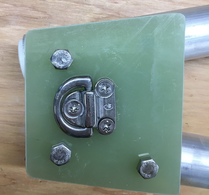
The front bracket is made from two plates of 1/4" G4. I cut each one separately with a jigsaw, then:
--Clamped the plates together
--Sanded them even, so the two would be identical
--Drilled 3/8" holes through the clamped plates

Next, I drilled holes in the tubes and test-fit. IIRC, I drilled the foward hole in each tube, bolted the assembly together, and then used the holes I'd already drilled in the G10 plates to guide drilling the aft holes.

I think it took me a couple tries and various rounds of test-fitting to get the angle right; thankfully, G10 isn't terribly expensive.

IMG_0384-2.jpg IMG_0048.jpg IMG_0385-2.jpg

I glued a small 'box' of G10 in between the poles, because I was mounting a pad eye on each plate, and wanted something to take the compression load of those bolts, avoiding additional unpredictable loads on the plates themselves.

The bolts on the port side are fixed, bolted to normal tension and capped with slip-on black plasic caps (for looks and to avoid scratching up other surfaces when moving the sprit around).

On the starboard side, I used a longer bolt with double lock-nuts tensioned to each other, leaving the bolt just loose enough to allow the rod to pivot. And a quick pin in the aft slot. This allows quick removal of the sprit:
--Remove the pin (pulling on the little Amsteel loop)
--Remove cotter pins on aft mounts (also with Amsteel loops)
--Pivot the starboard pole outward and off the aft rod
--Slide port side off the rod and remove sprit
(Note that it's still attached to the bobstay, so you're not at risk of dropping it in the water)
 
Aug 1, 2011
3,972
Catalina 270 255 Wabamun. Welcome to the marina
The single bolt on the Stb side will allow the plate to torque from the aft, increasing the loading to port at the Stb bolt and the aft port bolt. The bottom plate will not prevent or reduce this loading. In this case, you might be better to bolt the two plates together and have both of them on the top of the tubes. Additional bolts will not prevent the stresses on the Stb bolt, but will decrease the torque loading.
 

AaronD

.
Aug 10, 2014
723
Catalina 22 9874 Newberg, OR / Olympia, WA
The single bolt on the Stb side will allow the plate to torque from the aft, increasing the loading to port at the Stb bolt and the aft port bolt. The bottom plate will not prevent or reduce this loading. In this case, you might be better to bolt the two plates together and have both of them on the top of the tubes. Additional bolts will not prevent the stresses on the Stb bolt, but will decrease the torque loading.
Thanks, @Meriachee. I always appreciate thoughts from someone who knows more than me! But I'm not sure I'm envisioning exactly what you're describing. I probably didn't drink enough coffee today. :confused:

There's a quick pin as the 4th point of contact (symmetric with the aft bolt on the port side). It might (or might not) alleviate the forces you're thinking of. But it wasn't in place yet when I took those pictures. I should have taken another later in the process (I didn't drill it until after mounting the tube and rod, to be sure I got the angle correct). I dug around in the boat and found all the relevant parts; here's a picture showing the end product. Thoughts or suggestions?

P4170145.JPG
 
Aug 1, 2011
3,972
Catalina 270 255 Wabamun. Welcome to the marina
That looks better. I looked at the single bolt and saw a whole lot of twisting torque when the sail pulls, up and out from it. Think of how the plate will twist, and you’ll see what I’m seeing.
 
Sep 24, 2017
59
Catalina 22 #14720 Cheboygan
Back to the porta potty.
AaronD, Gene or anyone with similar knowledge. Got to the boat yesterday and measured from the deck to the lip where the v- berth board would sit. This came to 14 1/2 inches. The MSD head shows a height of 16 1/2 inches. How are you making this fit or are you not using the v-berth board?
 

AaronD

.
Aug 10, 2014
723
Catalina 22 9874 Newberg, OR / Olympia, WA
Back to the porta potty.
AaronD, Gene or anyone with similar knowledge. Got to the boat yesterday and measured from the deck to the lip where the v- berth board would sit. This came to 14 1/2 inches. The MSD head shows a height of 16 1/2 inches. How are you making this fit or are you not using the v-berth board?
Good question. My Dometic unit is 15" even, and that leaves about 5/8" of clearance under the V-berth board. If the one you're looking at is really 16-1/2, it wouldn't fit there.

P4170146.JPG P4170147.JPG
 
Sep 30, 2013
3,538
1988 Catalina 22 North Florida
Back to the porta potty.
AaronD, Gene or anyone with similar knowledge. Got to the boat yesterday and measured from the deck to the lip where the v- berth board would sit. This came to 14 1/2 inches. The MSD head shows a height of 16 1/2 inches. How are you making this fit or are you not using the v-berth board?
We don't use the board.

V berths look good in advertisements, but are too small for most adults to realistically sleep in. Besides, how would one use the potty at night?
 
  • Like
Likes: rpludwig

AaronD

.
Aug 10, 2014
723
Catalina 22 9874 Newberg, OR / Olympia, WA
We don't use the board.

V berths look good in advertisements, but are too small for most adults to realistically sleep in. Besides, how would one use the potty at night?
With a crew of 4, we don't have much of a choice; my son and I usually sleep in the V-berth. A few years from now, when the kids grow up and it's just 2 of us, I expect we'll like leaving the potty accessible.
 
  • Like
Likes: Gene Neill

AaronD

.
Aug 10, 2014
723
Catalina 22 9874 Newberg, OR / Olympia, WA
Bowsprit aft mounts

IMG_0387-2.jpg IMG_0386-2.jpg IMG_0049.jpg
The aft mounts are made from 1-1/2" round fiberglass rod. They're about 6" long total, and about 3" of that slides into the aluminum tube. The rod was actually slightly slightly thicker than 1-1/2", so I had to sand one end down a hair to fit into the tubes (the sanding picture above).

After sanding and test-fitting, my son and I wrapped another ~1/2" of 9oz glass tape around the ends (the difference in color is obvious in the pictures). For 2 reasons:
1) I needed to sand them down to the appropriate angle to fit the mounting bar in the bow, and that would leave the end pretty thin.
2) I wanted the ends thick enough to be _sure_ they couldn't slide up into the tube.

The bench sander did this pretty well, but it took an hour or more for each side. A couple reasons:
--I found it was easy to heat the glass up enough to start scorching it. Thankfully, I learned that early in the process, and was able to sand off the scorched bits.
--I stopped frequently to check the alignment, as it would be easy to take off too much

I drilled the 1/2" hole in each bracket. As I recall, it was pretty straightforward on the drill press.

Assembly: If I recall correctly, I mounted the sprit on the bow to glue the mounts into the tubes (to be sure the angles were correct (like the test-fit picture below, but with epoxy instead of masking tape). After that epoxy cured, I added a wrap or two of fiberglass tape around the exterior of the joint.
IMG_0420-2.jpg

Front caps: The caps on the front end are just ~1/2" long plugs made from the same 1-1/2" fiberglass rod. Sanded slightly so they'll fit in the aluminum tube, epoxied in place, and then sanded round on the bench sander. In the tubes, they were pretty easy to control while sanding.

IMG_0045.jpg
 
  • Like
Likes: Hardhead

AaronD

.
Aug 10, 2014
723
Catalina 22 9874 Newberg, OR / Olympia, WA
Bowsprit Bow Tube

IMG_0765.jpg IMG_0411-2.jpg IMG_0520-2.jpg

I wanted about a 1/2" SS rod, fit in a fiberglass tube. But the thickest 1/2" ID tube I could find was 3/4" OD, and that didn't seem quite big enough to me, as far as contact area with the bow and backing plates. I have no engineering calculations on that; I just wanted a bit bigger tube. So I bought 2 tubes - 1/2" ID - 3/4" OD, and 3/4" ID - 1" OD and nested them (as it turned out, the inner one is garolite and the outer one straight FRP, since that's what I found at McMaster-Carr).

Nesting the tubes was easy, with just a bit of epoxy to join them. But the ID of the inner one was just a hair undersized, so it took a fair bit of time with a drill and various hackish sanding solutions to widen it out so the SS rod would fit.

IMG_0417-2.jpg
I spent a lot of time thinking and measuring before drilling these holes... I guess I didn't take pictures of the actual drilling, as my hands were pretty well occupied. But the instructions at https://trogear.com/wp-content/uploads/Trogear-Install-Manual.pdf are helpful.

Also see
.

I measured 3-1/2" down from the deck and ~11-1/2" from the tip of the bow. I taped a string with a mark (at 12", IIRC) in place on the bow and marked the hull where it intersected my downward measurement on each side.

The process went something like this:
--Drill with a 1" hole saw on each side
--Test fit the tube.
--Epoxy G10 backing plates inside the bow (taping over the holes first, so I wouldn't squeeze epoxy out onto the exterior of the hull).
--Re-drill the 1" holes, through the backing plates
--Dremel the holes to clean up the angle so the tube would fit cleanly
--Epoxy the tube in place
--Epoxy a large SS washer onto the tube (so the mount rests against it instead of the tube itself (you can see that in the final exterior picture above)
--Paint (with a kids artist brush and a little Brightsides left over from the previous owner's hull paint job. It's sloppy old paint, but good enough for the few square inches I was painting)
 

AaronD

.
Aug 10, 2014
723
Catalina 22 9874 Newberg, OR / Olympia, WA
Bowsprit rod

IMG_0422-2.jpg IMG_0582-2.jpg

A 1/2" 316 SS rod was surprisingly affordable, at ~$12 (2 foot length). I was nervous about drilling the cotter-pin holes in the ends, but I had enough extra rod that I know I could mess something up and cut it off. And I had a bunch of HSS drill bits, so I could afford to waste a couple. And it turned out to be much easier than I expected.

A bit of online research found that the ~750 RPM low speed on my super-cheap drill press is just about right for drilling a 1/8" or 9/64" hole in 316 SS. You don't want to start a hole in 316 with a center punch - you'll instantly work harden the metal. So I clamped a V drill guide into my DP vise along with the rod. That way, the bit is constrained to drill straight and can't wander when starting. Don't forget some cutting oil on the bit. I wish I'd taken a picture. It looked hackish (and was), but it worked amazingly smoothly. Shocking!

I rounded the end off on a bench grinder, cut the rod to length with a Dremel, and repeated drilling and rounding the other end.


If I were to do it again, I would look at a 1/2" carbon fiber rod instead of SS (I still might replace it someday, just to shave some weight). Sometime after I bought the SS, I found that pultruded CF is very reasonably priced (I don't see it on McMaster currently, but it's only ~$15 on eBay). My only hesitation is that in pultruded rod, the fibers will mostly run lengthwise. IIUC, that means it will be phenomenally strong in compression or tension, but the force in this application is a bending force; I suspect it would be completely fine, but that would be worth some mechanical engineering calculations. CF is amazingly strong, but brittle - it won't give you much (if any) warning before shattering completely. Thoughts welcome from the mechanical engineers in the crowd.
 

AaronD

.
Aug 10, 2014
723
Catalina 22 9874 Newberg, OR / Olympia, WA
Removable Double Furling-line Fairleads

The continuous-line furler requires a spliced loop furling line (continuous - imagine that!). The load is low, and stretch doesn't matter, so I used Sta-Set. Many setups route it through stanchion-mounted fairleads (like https://www.velasailingsupply.com/selden-stanchion-double-fairlead-for-continuous-furling-line/). But I don't have lifelines or stanchions, so we needed a few fairleads to route the line from the cockpit to the bow.

I have a couple double fairleads (like https://www.westmarine.com/buy/spinlock--bulls-eye-multiple-organizer-double-bulls-eye--14695092), but something made me nervous about splicing the line permanently in place (or maybe it's just that it was ~100 degrees out and I wanted to do the splicing in my air-conditioned house).

So I made a couple two-part fairleads from Starboard and fiberglass. The base is 1/8" fiberglass (which seals nicely to the deck with butyl tape). The fairlead itself is two thin sheets of Starboard, screwed to the fiberglass base, and drilled. The Starboard parts can be mounted and removed without impacting the deck or sealant.

P4300155.JPG

I didn't take enough pictures, but the process was:
--Clamp starboard sheets together and drill through the split / joint (easiest with a drill press vise, but a bench vise and hand drill would work)
--Round the edges with a countersink
--Drill and countersink vertical holes through Starboard for screws into the fiberglass
--Sand the edges of the starboard (yes, in the close-ups you can see my sloppy sanding)
--Tap holes in the glass bases (for screws through Starboard into glass)
--Spray paint fiberglass
--Mount bases on the boat (Since they don't need through-bolts, I overdrilled, filled with thickened epoxy, and tapped threads into the epoxy)
--Route lines through Starboard and screw to base

IMG_0423-2.jpg IMG_0424-2.jpg IMG_0511-2.jpg P4300156.JPG P4300157.JPG

I've pulled the control line a couple times, and it was nice to do that without needing to re-seal the fairleads.
 
  • Like
Likes: Hardhead
Apr 11, 2017
571
Catalina C22 Solomon's Island, MD
That's some masterful use of G-10. I'll bet it took some guts to drill those 2 holes clear through the bow - but the end result is impressive. Might well be the 1st C22 ever modified in such a way. Excellent instructions as well-
 

AaronD

.
Aug 10, 2014
723
Catalina 22 9874 Newberg, OR / Olympia, WA
Code Zero Running Rigging

I'll finally try to finish up my notes on the Bowsprit / C0 project.

Sheets: New England Ropes Flight Line.
Pros:
--Doesn't absorb water - a big plus, as the sheets are likely to get wet when jibing a big sail
--Good reputation for handling, and it's supposed to improve with use.
--Relatively low stretch (not the lowest, but this is a light-wind sail, so the loads are pretty low, and we aren't as concerned with the sheets stretching in a gust).
--Much cheaper than Warpspeed and most other high-tech lines
--Light weight
--Cover can be stripped (making it even lighter). With this in mind, we went with 5/16" instead of 1/4" for easier handling, and stripped the end.
If I were to do it over again, I might go for the 1/4". Less weight on the sail in light wind, and cheaper too. At the cost of handling thinner sheets. I might still pick up a set sometime; we'll see.

Cons:
--The polypropylene cover can melt if slid over a winch at high speed. But we're cruisers, so we're not likely to do anything at high speed.

Cost: 100 feet of 5/16" Flight Line at $1.39/ft, on WM's 40%-off-all-line sale = $83

P5100172.JPG

Sheet blocks: Lewmar 40mm lashing blocks, bought on sale for about $15 each, withAmsteel loops spliced through them. For the moment at least, I just cow-hitch them to the stern cleats. Maybe they'll get dedicated mounts someday, but the cleats are working for now. Total cost about $32 including the Amsteel.
P4300158.JPG

Halyard: 90' of 5/32" Endura 12, about 70' of which is covered with Sta Set. 40mm block, and a Ronstan 'Shock' sheaveless block to form a 2:1 (To furl a C0 or asym, you need plenty of luff tension, and the 2:1 means we don't have to winch it to furl). With a little loop of Amsteel attached to the shock to clip the swivel to (I spliced that loop using Allen's instructions at http://l-36.com/loop). Mocked up in the thumbnail below, without the sail or top swivel.
IMG_0581-2.jpg

Cost: ~$77
E-12: ~$.40/foot * 90 = $36
Sta-set: $31
 

AaronD

.
Aug 10, 2014
723
Catalina 22 9874 Newberg, OR / Olympia, WA
Adjustable backstay

Our original backstay cable was kinked and of unknown vintage. An Amsteel/Dyneema replacement seemed like a good option. It's economical and trims a little weight aloft. Note that normal Dyneema will 'creep' (enlongate) over time if under constant load. So for standing rigging, you need the heat-set versions. But the backstay is intended to be adjustable; several inches of creep over a few years would be fine. So I didn't see any need for heat-set line here.

The design is the same as CD's (https://www.catalinadirect.com/shop...djustablec-22-and-c-22-sport/?SearchResults=1). I used 5/32" for the backstay (breaking strength 4k lbs, safe working load of ~800 at 5:1 safety factor). 1/8" would probably be OK, but I upsized for a bit more strength and UV resistance. 5/32" Dyneema isn't always easy to find (1/8" and 3/16" are more common; SBO doesn't seem to have 5/32 at https://shop.sailboatowners.com/prod.php?6266), but if you look around, you can get 5/32" Amsteel or Endura 12 for ~$.40/foot. I found a 50' hank of Endura 12 for $21 at hamiltonmarine.com.


Cascade line: 3/16" Amsteel. For strength, the 5/32" would be completely fine; I don't remember why I used 3/16". Maybe I had a piece left over from something else.

Control line: I used a bit of 1/4" Samson MLX I had from some other project, but Sta-set or XLS would be fine. It's a relatively short length of line - from the numbers at http://l-36.com/line_stretch.php, I estimated ~.7" of stretch at 400 lbs load.

P4300161.JPG P5160173.JPG P4300162.JPG P4300163.JPG

For several years, we used the 4:1 block and tackle that came with the boat (8:1 with the cascade block). For this season, we're replacing the tackle with a 6:1 made of Harken 29mm blocks, primarily because the cam cleat will be much easier to adjust than the original block with a V-cleat (and because I had one of the triple blocks available as I redesigned our outhaul). And I originally used a Ronstan 30mm block for the cascade block; I just replaced it with a low-friction ring. The total cascade is now a 12:1; the low-friction ring probably loses ~15-20% (Allen measured 17% at http://l-36.com/low_friction_rings.php), for a net of ~10:1.

So the pictures here are of an untested variant. I usually try to stick to posting mods after I've used them for awhile. But conceptually, this is pretty similar to the version we've been using for a few seasons. And a couple C-22 sailors have asked about backstays this spring, so I thought I'd post this now.

Cost: ~$190 w/shipping
50' 5/32" Endura 12: $21
10' 3/16" Amsteel: ~$5-10
Ronstan 13/29mm low-friction ring: $11
Harken 347: $73 (eBay, new)
Harken 344: $51
~15' 1/4 line: ~$5-10

Personally, I think this is a considerably better system than the one CD sells for $400. No danger of kinking cables, less weight aloft, and easier for me to maintain (splices instead of swages). Hope someone finds it helpful.
 
May 24, 2018
31
Catalina 22 Norcal
Adjustable backstay
Personally, I think this is a considerably better system than the one CD sells for $400. No danger of kinking cables, less weight aloft, and easier for me to maintain (splices instead of swages). Hope someone finds it helpful.
Agreed. If only it was class legal.
 

AaronD

.
Aug 10, 2014
723
Catalina 22 9874 Newberg, OR / Olympia, WA
Agreed. If only it was class legal.
Thanks. And yes, I'm afraid my boat won't ever be class legal. But then, my paranoid repairs / enhancements mean she's also carrying too many extra pounds to ever be competitive. :what:
 
Sep 30, 2013
3,538
1988 Catalina 22 North Florida
Thanks. And yes, I'm afraid my boat won't ever be class legal. But then, my paranoid repairs / enhancements mean she's also carrying too many extra pounds to ever be competitive. :what:
Heavy or not, I'll bet you can beat a lot of boats you "shouldn't" be able to. ;)

I wouldn't be without an adjustable backstay. I have the CD setup you linked to, except I run the tackle upside down, relative to their illustration. I find the control line easier to reach and operate that way.
 
  • Like
Likes: Hardhead