LiFePo4 Refresh

jviss

.
Feb 5, 2004
7,089
Tartan 3800 20 Westport, MA
Actually they all do.

Some do it directly such as all of the inverter generators like the Honda EU2200i. In the specs they tell you that it is 2200W starting and 1800W continuous. They then translate that through the power equation P=IV to 18.3A @ 120 starting and 15A @ 120 continuous. [I will assume that you will call foul and say this is a different animal but it is not. All inverter generators are a fuel powered engine that uses the rotational mechanical power (hp) of and fuel powered engine to turn and alternator that converts it first to AC electrical power (watts) and then rectifies it to DC electrical power (watts) before running it through an inverter that converts the DC back to AC at a regulated 120v.

Some do it indirectly. For some reason that I cannot understand or guess at, the automotive and marine alternator market has chosen to rate their power output indirectly by the "IV" side of power equation P=IV. They list the power of the power generating device called an alternator as 125A @ 12-volts which when written as a mathematical equations would be 125A x 12v which my calculator tells me is "1500Amp-volts" but per the rules of unit conversion should be simplified to 1500-watts.

BTW when was the last time that you heard of a power generation station such as being rated by their amp capacity. Never seen a mega-Amp rating but see lots of reference to megawatt generators. Electrical power is measured in watts and that cannot change. If you prefer to examine your watts of power based on the number of amps you get at a specific voltage that is fine but it does not change the fact that what we are talking about is watts of power. Personally, when I am looking at solar devices which are always rated in watts, the first thing I do is to find out what that will "do" for me by finding out how many amps I can put into my battery so I divide the watt rating by 13.6v (an average charge current) to get the maximum amps that it will deliver to the battery during charging.
I'm talking about alternators, not generators or power stations.

Again, I'd like to see one alternator specification that rates it in terms of maximum power instead of current-RPM-temp. And, I'd like to see that magical, constant power alternator!
 

jviss

.
Feb 5, 2004
7,089
Tartan 3800 20 Westport, MA
The alternator connected to LFP will be at battery voltage while the current slowly increases SoC and voltage from about 0% SoC to almost 98% SoC.finally at the very very end of the charge cycle the voltage will rise rapidly to the absorb voltage and current will decline rapidly.
Yes, understood
At any point below the target voltage the alternator will be working as hard is it can & the regulator will be driving the field at 100% unless the temp sensor tells it to back off on the field to let the alt cool...
Or, unless the regulator has a current limit, no? I can program my Link 2000R to a maximum current.
Just because an alternator is striving to get to 14.4 V does not mean that happens immediately. It cannot due to the large stubborn load that it is trying to charge. At a .5C charge-rate the alternator is at battery voltage until about 98%SoC. Once the battery voltage finally hits absorption the absorption duration needs to be short typically, 2 minutes to 30 minutes ..
O.K., yes, I get it now. So, the alternator will push current trying to regulate to 14.4, but the AO will stay at batter voltage until the SOC increases to the point where the voltage comes up. So why, then, do we see recommended absorption voltages of 14.4, etc.? Based on your explanation it seems like it's a controlled current charge with terminal voltage being sensed.
 
Apr 5, 2009
3,105
Catalina '88 C30 tr/bs Oak Harbor, WA
... Field current is rather small, is used to create the magnetic flux that cuts the stator windings as the field (wound on the rotor) rotates within. The output current is from the stator, through the diodes and is a function of the load impedance (yes, impedance!) and the output voltage. Regulators are designed to control the field current to regulate the alternator output voltage.
The green highlighted text is completely accurate but the red text... The regulator controls the field current indirectly by adding resistance to the field wire which lowers the voltage that is delivered to the fixed resistance of the electromagnets in the rotor. This lower voltage in the field wire creates less current "I=V/R". What is not true is that this reduction in the field current does NOT regulate the voltage output. It regulates the POWER generated. The voltage is the result of balance between the current coming into the battery and the internal resistance of the battery. This is why we get "diode boom" when the battery is disconnected because the sudden increase of resistance to infinity causes the voltage to go there too.

More nonsense. LA batteries have a rather complicated impedance that changes as the SOC changes. See this paper:
Generalized Lead-Acid based Battery Model used for a Battery Management System

Here's the equivalent circuit diagram for a lead acid battery the author developed:

View attachment 203309


I give up, @Hayden Watson , the above is just gobbledygook.
I fully read this scientific paper and found it to be very informative but your interpretation to be hilarious. After reading it, I did a word search for the word "impedance" and found it used 20 times. I also searched for "resistance" and found it 22 times. The most interesting section on impedance is is copied below. The impedance that they are talking about is the result of a small AC current that they added to the batteries in order to allow them to do an electrochemical impedance spectroscopy (EIS) which gave them a method to much more accurately calculate the internal resistance of the battery. In layman's terms, they added an AC current so that they could produce impendence so that they could calculate resistance.

impedance.png
 
Apr 5, 2009
3,105
Catalina '88 C30 tr/bs Oak Harbor, WA
I'm talking about alternators, not generators or power stations.

Again, I'd like to see one alternator specification that rates it in terms of maximum power instead of current-RPM-temp. And, I'd like to see that magical, constant power alternator!
And again, I will say that all alternators are listed by their rated power. They are power generating devices that convert rotational energy to electrical power. We can all agree that we have seen rating of 125A @ 12v. That is a rating of power because P=IV and the proper unit for power is watts.
For the end user, it is convenient to have the power listed in amps at a given voltage because it makes it simpler for him to think about how long it will take it to cram the power we have used back into our batteries which are rated in amp-hours.
 
Apr 5, 2009
3,105
Catalina '88 C30 tr/bs Oak Harbor, WA
I'm talking about alternators, not generators or power stations.
You do realize that all power stations and generators are "alternators" that use the same rotor/stator system to convert rotational power into electrical power, right?
 
  • Like
Likes: JamesG161

jviss

.
Feb 5, 2004
7,089
Tartan 3800 20 Westport, MA
What is not true is that this reduction in the field current does NOT regulate the voltage output. It regulates the POWER generated.
That's not so. The control of the field current with regulate the output voltage with a load connected such that the system is within the range of regulation.
This is why we get "diode boom" when the battery is disconnected because the sudden increase of resistance to infinity causes the voltage to go there too.
No, the "diode boom" is because you can't change the current in an inductor instantaneously, and Ohm's law must be satisfied, so the Voltage spikes.
I fully read this scientific paper and found it to be very informative but your interpretation to be hilarious.
Likewise, I'm sure.
 

jviss

.
Feb 5, 2004
7,089
Tartan 3800 20 Westport, MA
You do realize that all power stations and generators are "alternators" that use the same rotor/stator system to convert rotational power into electrical power, right?
A power station or a generator (like the Honda) are systems that include the alternator as a component. The overall system is usually specified in terms of power output. Automotive and marine alternator components are not. That's why I asked you to back up your assertion with an example, which you have not. I did. (See my link to the Bosch alternator spec.)
 

jviss

.
Feb 5, 2004
7,089
Tartan 3800 20 Westport, MA
Look, I'm sorry that I've talked down to folks on matters electrical, @Hayden Watson included, Sorry.

People have their heels dug in, and we're not going to convince either of us in any way. I'm happy with my understanding of alternators, which is convention, and common, as far as I can determine. i admit I don't know everything, but I'm on a. quest for understanding of LFP's, and, as we've seen, not all of this stuff about charging batteries is intuitively obvious.
 
Last edited:
Apr 5, 2009
3,105
Catalina '88 C30 tr/bs Oak Harbor, WA
Good luck with that with LFP..
The PM is built to the same standard as the old Ample alt...We built a similar version only much improved over where Ample left off.... We were using the best quality magnet wire USA wound stators & rotors, 75A 400V diodes vs. 50A 200V. We used the same quality diodes used in massive 300A ambulance alternators. We also improved the heat sinking and used a bronze B+ bolt which also helped to minimize localized heating. Ample made the outlandish claim that these alts were constant duty (before AGM and LFP hit the scene)..When LFP came along.... Smoke....


Even on our AMP-IT HD125ER we would never suggest 100A continuously into LFP...
@Maine Sail I have an Ample 105A alternator that I want to keep alive as long as I can. For this alternator, what do you recommend for maximum charging current to be set to for charging an LFP bank? I will also have a thermostatic control on it to shut it down above a set temperature and not restart it until it cools below a reset temp. Do you have a recommendation for the cutoff and restart temperatures. Where is the best place on the alternator to mount the thermistor?
 
Apr 5, 2009
3,105
Catalina '88 C30 tr/bs Oak Harbor, WA
...
Maine Sail said
"Just because an alternator is striving to get to 14.4 V does not mean that happens immediately. It cannot due to the large stubborn load that it is trying to charge. At a .5C charge-rate the alternator is at battery voltage until about 98%SoC. Once the battery voltage finally hits absorption the absorption duration needs to be short typically, 2 minutes to 30 minutes .. "

O.K., yes, I get it now. So, the alternator will push current trying to regulate to 14.4, but the AO will stay at batter voltage until the SOC increases to the point where the voltage comes up. So why, then, do we see recommended absorption voltages of 14.4, etc.? Based on your explanation it seems like it's a controlled current charge with terminal voltage being sensed.
This is the same thing that I have been saying. The alternator cannot push current at a specific voltage because the voltage will always be the same as the battery (ignoring wiring losses) so the alternator is not set to a voltage. It is monitoring the voltage (hopefully at the battery +&-) and limiting the power output of the charge source so that the current does not push the battery above the set voltage.
I would suggest that you read up on CC/CV charge profiles for further info. The point I have been trying to make is that if until the regulator tell the alternator to cut back on output, it will put out as much as it is capable of doing based on engine power available and rpm's. This causes heat which if left unchecked for a long time will damage the alternator as Main Sail has shown. If you have an external regulator that does not have temperature sensing control, you can manually cut back the power output (yes I agree with you that is Amps at battery voltage) to a lower level to keep it from getting too hot. The manual reduction in power is done by wiring a rheostat in-line in the field wire (ussually blue). If you test each side of the rheostat during the CC stage with a volt meter, you will find battery voltage on the regulator side and battery voltage or less depending on how you set the rheostat on the alternator side. Once the set-point voltage is reached, the regulator side voltage will start to drop which will also cause the alternator side to drop and the battery voltage will stay at the set-point voltage.
As for your question "So why, then, do we see recommended absorption voltages of 14.4, etc.?"
You do not see that recommendation for LFP because a long absorption period is harmful to them. Years ago, I asked Maine if one of his recommended shore chargers, the Sterling ProCharge-U was a good choice for an LFP install and he told me that it was a terrible choice because it set the absorption time to equal the time in bulk which would destroy the LFP. With LFP your batteries should spend almost no time at the set-point voltage because once you get there the battery is full and the charge should go to float down around 13.4v to keep from over charging them. One of the best charge profiles for LFP is constant current (as much as your system can safely produce without overheating and damaging itself, than CV constant voltage at the set-point for a few more minutes, then turn off or float at a voltage less than the resting voltage of the battery.
FLA needs a long absorption time because as they get closer to full, the internal resistance goes up so that they cannot accept much current and only a prolonged absorption phase will get them to a full condition.
 

jviss

.
Feb 5, 2004
7,089
Tartan 3800 20 Westport, MA
I'm beginning to think the ideal LFP charger is just bulk, no absorption, and then regulate to the desired SOC voltage to power loads without depleting the bank.
 
  • Like
Likes: Hayden Watson
May 17, 2004
5,595
Beneteau Oceanis 37 Havre de Grace
I'm beginning to think the ideal LFP charger is just bulk, no absorption, and then regulate to the desired SOC voltage to power loads without depleting the bank.
Thinking by way of analogy to consumer electronics, this has been the trend for lithium ion chargers. Some phones and computers now have a charging option where they’ll bring the battery to 80% immediately, then float it there until the user says they want the full capacity, or an algorithm determines it’ll be needed. In the case of my iPhone it means there’s a few hours each night where the battery isn’t being taxed floating at 100%.

1647034511003.png
 
  • Like
Likes: jviss
Apr 5, 2009
3,105
Catalina '88 C30 tr/bs Oak Harbor, WA
@Maine Sail If I have a 24v system, is there any difference in the alternator if it has an external regulator or is the voltage all controlled by the regulator? When I look at regulators, I see 12v specs and 24v specs but cannot tell if there is any difference in them other than the regulator.
 

jviss

.
Feb 5, 2004
7,089
Tartan 3800 20 Westport, MA
Thinking by way of analogy to consumer electronics, this has been the trend for lithium ion chargers. Some phones and computers now have a charging option where they’ll bring the battery to 80% immediately, then float it there until the user says they want the full capacity, or an algorithm determines it’ll be needed. In the case of my iPhone it means there’s a few hours each night where the battery isn’t being taxed floating at 100%.

View attachment 203315
My new Macbook does that. It has a smart charging algorithm, and learns my habits, keeping the batt at 80% unless it anticipates unplugged use, where it charges to 100%.
 

jviss

.
Feb 5, 2004
7,089
Tartan 3800 20 Westport, MA
@Maine Sail If I have a 24v system, is there any difference in the alternator if it has an external regulator or is the voltage all controlled by the regulator? When I look at regulators, I see 12v specs and 24v specs but cannot tell if there is any difference in them other than the regulator.
I know you're asking Rod, but I'm going to jump in and say no. The alternator has no idea. It's the voltage regulator that is designed for either 12V or 24V systems, and it will control the field current to regulate to the set point, or, in the case of 3-stage regs, to hit the acceptance voltage, and then bring it down to float.
 
Last edited:
May 17, 2004
5,595
Beneteau Oceanis 37 Havre de Grace
@jviss this video just came up in my YouTube feed and reminded me of this discussion.


Some interesting things I took from it -
- The conventional alternator at 3000 RPMs put out 80 amps, which is less than the Balmar alternator at 3600 RPMs. This suggests that although the battery could’ve absorbed more, the traditional alternator didn’t just keep pushing more. I’m guessing it’s an 80A alternator and that’s as far as it went.
- When the traditional alternator burnt it was only pushing 65A - less than it was capable of. So the burnout wasn’t directly attributed to just over-current, it was from insufficient cooling to be able to sustain a large current over time.
 
Feb 6, 1998
11,703
Canadian Sailcraft 36T Casco Bay, ME
@jviss this video just came up in my YouTube feed and reminded me of this discussion.


Some interesting things I took from it -
- The conventional alternator at 3000 RPMs put out 80 amps, which is less than the Balmar alternator at 3600 RPMs. This suggests that although the battery could’ve absorbed more, the traditional alternator didn’t just keep pushing more. I’m guessing it’s an 80A alternator and that’s as far as it went.
- When the traditional alternator burnt it was only pushing 65A - less than it was capable of. So the burnout wasn’t directly attributed to just over-current, it was from insufficient cooling to be able to sustain a large current over time.
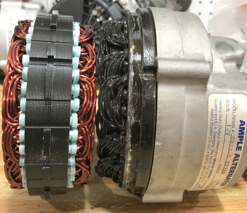
Most stock alternators do not have the capability to charge an LFP battery without eventually sustaining damage.An external regulator can help prevent this provided you start with a well built alternator to begin with and you then program the regulator correctly....
2022-03-09_10-24-52.jpg


and the Ample alts are not immune to this either, despite their claims of "continuous duty".......
Z-IMG_7657.JPG
 
Apr 5, 2009
3,105
Catalina '88 C30 tr/bs Oak Harbor, WA
Most stock alternators do not have the capability to charge an LFP battery without eventually sustaining damage.An external regulator can help prevent this provided you start with a well built alternator to begin with and you then program the regulator correctly....
View attachment 205672

and the Ample alts are not immune to this either, despite their claims of "continuous duty".......
View attachment 205673
Well Rod I have done it. I ordered LFP batteries for my boat. Your comments on the Ample alternators are timely because I have an Ample 105 installed. I will be adding a PWM controller to my field wire between the regulator and the alternator so that I can turn down the max output to a safe level and to keep from turning my poor little 3/8" v-belt to dust.
What do you suggest I set my max output to. I suspect that if I am at a level that will work for the belt, it will also run cool enough. Later I plan to add a serpentine belt kit but that will need to be down the road so for now I will just limit the current.
I was thinking somewhere in the 60A to 70A range.
 

jviss

.
Feb 5, 2004
7,089
Tartan 3800 20 Westport, MA
Yikes! I have an Ample Alternator rated 125A. I have run it continuously (mistakenly) with a 100A limit charging FLA banks, but of course that's not really continuous since the stupid smart regulator doesn't maintain constant current during bulk, for some reason - it tapers off as you approach the acceptance voltage set point.

In fairness, it is strongly dependent on the airflow and ambient operating temperature. Ample published a chart in their manual [1] de-rating these depending on RPM and ambient operating temperature.

The best thing is to have a regulator like the Balmar ARS-5 that has an alternator temperature sense port and will back off the output as things heat up.

[1] Ample Alternators
 
Apr 5, 2009
3,105
Catalina '88 C30 tr/bs Oak Harbor, WA
Yikes! I have an Ample Alternator rated 125A. I have run it continuously (mistakenly) with a 100A limit charging FLA banks, but of course that's not really continuous since the stupid smart regulator doesn't maintain constant current during bulk, for some reason - it tapers off as you approach the acceptance voltage set point.

In fairness, it is strongly dependent on the airflow and ambient operating temperature. Ample published a chart in their manual de-rating these depending on RPM and ambient operating temperature.

The best thing is to have a regulator like the Balmar ARS-5 that has an alternator temperature sense port and will back off the output as things heat up.
It is not the regulator that is tapering off the current. That is caused by the batteries internal (infernal?) resistance increasing as the battery fills. It will run at CC at lower voltage but as the voltage gets near the bult setpoint, it will change to CV and decrease the output to prevent overshooting the voltage.