The case that @Maine Sail was referring to, as far as I can tell, was one where a Yanmar 125A alternator with a "dumb" voltage regulator was connected to a (presumably) high AH LFP bank. So, the dumb regulator dutifully tried to maintain the charging voltage by increasing the field current, and probably hit the rails on that, put out as much current as it possibly could, which exceeded the rating of the alternator, burning it up. So, it was the lower impedance of the bank that killed it. This wouldn't have happened with a small bank, like a regular starting battery.
LiFePo4 Refresh
- Thread starter jviss
- Start date
The rating (in watts) for a given design is provided by the mfr on their spec sheet based on a design rpm and field voltage. So, at the specified rpm and with the specified field voltage the alternator will put out the rated number of watts. The watt output in the design is based two primary factors. 1. The number of times the stator crosses the magnetic field based on the number of poles (fixed) and the rpm's (variable). 2. The strength of that magnetic field based on the number of field windings (fixed), resistance of the field winding wire (fixed) and the field voltage (variable). If the RPM's or field voltage or or both of them are above the rating, it will put out more than the rated watts. One handy aspect of this is that with a low battery voltage, you will have by default a lower field voltage so the max watts is somewhat self-limiting because you cannot produce as many watts when connected to an 11v battery as you can with a 13.6v. This greatly helps limit the watts (and the evil byproduct heat) on a FLA setup because of the wide range of voltages they sit at and that the IR increases with voltage so there again it is self limiting. The self-limiting thing doesn't happen with LFP because they have over 13v until nearly fully drained. When you combine this with how easy it is to get really big LFP banks, it becomes easy to overwork and overheat the alternator unless you monitor the stator temperature and adjust the field voltage to keep it within limits.What is an alternator rating, after all? What does it mean to have a 125A alternator? Where does it say "125A for only one hour," or some such thing?
Why do you think the load has nothing to do with this? How about trying a short circuit, and seeing how long the alternator lasts? Will it only source 125A into a dead short? If not, why would it only source 125A into a low impedance bank? What's controlling the maximum current output? Is the regulator measuring current? Not the typical one, the typical one is measuring voltage, as in "voltage regulator." Smarter ones detect current through a shunt in the alternator output, and can limit output, as in my Freedom 20/Link-2000R system. But the typical simple setup doesn't. That's why the size of the bank and the alternator have to be matched properly, to avoid burning the alternator.

Yes, I am saying that alternators design output is properly described in watts not amps. They generate electric POWER. The electrical power equation is P (power) = v (volts) x I (amps). Any amp rating is only correct at a specific voltage but the batteries that they are connected to have a voltage range of 10.5v (0%SOC) to 14.2v (100%SOC at top of CC charge phase). So, for our theoretical 125A @ 12v alternator we find that it is putting out 125A x 12v = 1500-Watts of power. If this alternator is connected to a flat dead FLA battery in good condition the amps output would be 1500W / 10.5v = 142.8A. As you correctly stated, the heat output is based on the current or amps so for the same 1500w of power the alternator will generate more heat. If the battery is almost full but not yet at absorption the current would be 1500W / 14.2v = 105.6A.Alternators have been rated in current output for over a hundred years. It makes little difference what the output voltage may be, it's the current through the stator that makes the heat.
Are you saying the alternator is really rated in Watts, not Amps?
A continuous rating at a particular ambient temp and airflow are just that, and the alternator so rated should run like that forever.
The reason I say it is a north American thing is that when I watch YouTube videos from knowledgeable contributors from Europe and Australia, they always refer to the Watts output of the alternator. The amps are dependent on a variable of Volts so as volts to up, amps go down and vise-versa.
@Hayden Watson , I don't know where to begin. You've written two long, authoritative-sounding posts that, in my opinion, are just conceptually and practically incorrect. Rather than attempt a fisking of them, which would be time consuming and perhaps pointless, please allow me to make a couple of observations that are contrary to your presentation. Before I do some let me say that I am fine with being shown I'm wrong, and learning something. My academic experience with alternators, generators, and motors was my undergraduate "power" lab, a 1 year lab while I was in school for electrical engineering. But that was 42 years ago, and I, unfortunately, discarded my textbooks and notebooks several years ago, and, of course, my recollection could be foggy. My practical knowledge is only with alternators on boats in the last 20 or so years.
Specifications
I have never seen an alternator specification that specifies alternator operating characteristics in terms of Watts. It has always been, for a given nominal voltage output of 12 or 24 or 48VDC, a maximum current output at a particular RPM and ambient temperature. For example, a 12V Bosch rated at 122A at 6,000 RPM and 80º C.
Example specification:
Bosch Motorsport | Alternator B5
Operation
In that it's the magnetic flux of the field (carried on the rotor) that induces the EMF in the stator, it is the field current that controls the alternator output, not the field voltage. The simplest, internal regulators adjust field current to maintain the set output voltage, which, for example is 14.4V.
Output
The alternator doesn't "know" its ratings. I t must be integrated into a properly designed system in order to not exceed its ratings. System considerations are environment (temp), desired output, and load characteristic. So, if you put a bigger load on an alternator, by, for example, attaching it to a bank that has a lower impedance than perviously, like switching from FLA to LFP, the output current will increase. Ohm's Law, in the simplest analysis: I = V/R. Note that Volts and Amps go up proportionately, not as you stated:
Note that batteries are more complex than just a simple resistance, but in the first order analysis the analogy is useful.
Note also that in your analysis you are using a Watt rating as an independent variable, and saying that the current output is a function of a fixed power rating and the output voltage. This is also incorrect. The power output is a product of the current output and output voltage, the latter two being controlled by the regulator (assuming sufficient rotor speed). So, put 0.1Ω across the output of that Bosch B5 and spin it at 6k RPM in 80ºC and it will put out 144A all day. Put 0.05Ω across the output and it will put our 288A for a short period of time (assuming the regulator can put out sufficient field current), until it burns out - probably wreck the stator.
And that's all there is to it.
Specifications
I have never seen an alternator specification that specifies alternator operating characteristics in terms of Watts. It has always been, for a given nominal voltage output of 12 or 24 or 48VDC, a maximum current output at a particular RPM and ambient temperature. For example, a 12V Bosch rated at 122A at 6,000 RPM and 80º C.
Example specification:
Bosch Motorsport | Alternator B5
Operation
In that it's the magnetic flux of the field (carried on the rotor) that induces the EMF in the stator, it is the field current that controls the alternator output, not the field voltage. The simplest, internal regulators adjust field current to maintain the set output voltage, which, for example is 14.4V.
Output
The alternator doesn't "know" its ratings. I t must be integrated into a properly designed system in order to not exceed its ratings. System considerations are environment (temp), desired output, and load characteristic. So, if you put a bigger load on an alternator, by, for example, attaching it to a bank that has a lower impedance than perviously, like switching from FLA to LFP, the output current will increase. Ohm's Law, in the simplest analysis: I = V/R. Note that Volts and Amps go up proportionately, not as you stated:
That statement is incorrect. If you increase the voltage, the current will increase, not decrease.The amps are dependent on a variable of Volts so as volts to up, amps go down and vise-versa.
Note that batteries are more complex than just a simple resistance, but in the first order analysis the analogy is useful.
Note also that in your analysis you are using a Watt rating as an independent variable, and saying that the current output is a function of a fixed power rating and the output voltage. This is also incorrect. The power output is a product of the current output and output voltage, the latter two being controlled by the regulator (assuming sufficient rotor speed). So, put 0.1Ω across the output of that Bosch B5 and spin it at 6k RPM in 80ºC and it will put out 144A all day. Put 0.05Ω across the output and it will put our 288A for a short period of time (assuming the regulator can put out sufficient field current), until it burns out - probably wreck the stator.
And that's all there is to it.
A couple of more observations
Then you say this:
Because of the chemistry of FLA, the current will be higher with a more depleted bank, and, in any case, most smart regulators will attempt to regulate to a fixed current in the bulk phase. Once in ACCEPT the current will taper off at a fixed (regulated) voltage. However, if you drop-in an LFP bank and charge at a fixed (regulated) voltage without current limiting, the effective lower impedance of that bank could result in more current than the alternator can withstand.
The field voltage has nothing to do with the output voltage of the alternator. Note that the battery voltage and alternator output voltage are the same if they are connected directly and there are insignificant drops in the wire.One handy aspect of this is that with a low battery voltage, you will have by default a lower field voltage so the max watts is somewhat self-limiting because you cannot produce as many watts when connected to an 11v battery as you can with a 13.6v.
Then you say this:
While you first say you can't produce as many Watts connected to an 11V battery as you can with a 13.6V battery, you later make calculations of current at a fixed Power of 1500W. How does that make sense?So, for our theoretical 125A @ 12v alternator we find that it is putting out 125A x 12v = 1500-Watts of power. If this alternator is connected to a flat dead FLA battery in good condition the amps output would be 1500W / 10.5v = 142.8A. As you correctly stated, the heat output is based on the current or amps so for the same 1500w of power the alternator will generate more heat. If the battery is almost full but not yet at absorption the current would be 1500W / 14.2v = 105.6A.
Because of the chemistry of FLA, the current will be higher with a more depleted bank, and, in any case, most smart regulators will attempt to regulate to a fixed current in the bulk phase. Once in ACCEPT the current will taper off at a fixed (regulated) voltage. However, if you drop-in an LFP bank and charge at a fixed (regulated) voltage without current limiting, the effective lower impedance of that bank could result in more current than the alternator can withstand.
Here is the ISO standard for alternator ratings:
Note that it does not specify anything about being able to sustain that output for any length of time - output rating is based only on the maximum amount of current that can be “supplied” at a specific voltage in an ambient temperature of 23C.
Here are the specs for an 80A alternator on a Yanmar 3YM30
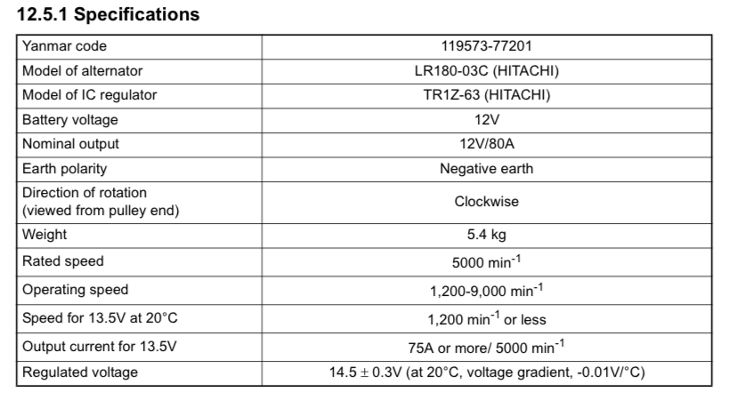
And the output characteristics for the same alternator -
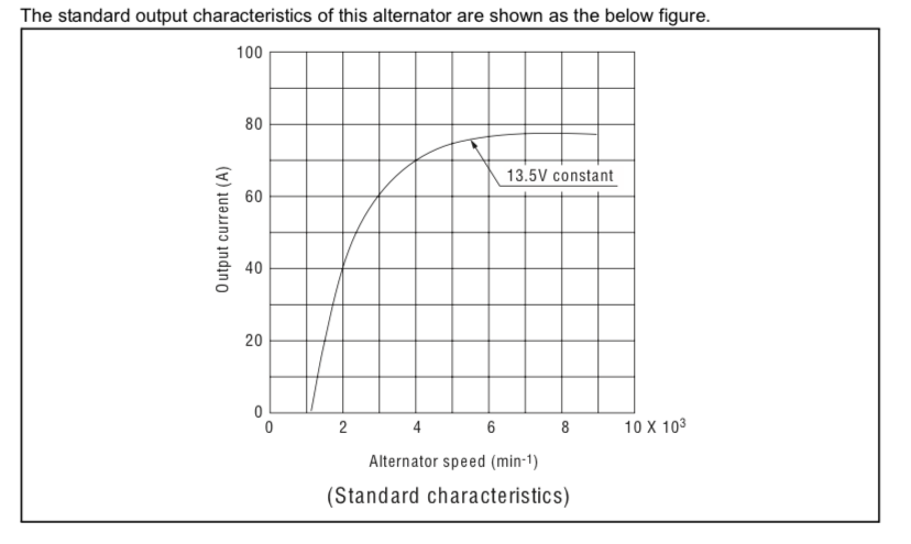
I don’t see anything in those specs that suggests that the output can grow over 80A if the load is a lower resistance*. As long as the output is confined to 13.5V the output will not grow above 80A. I don’t know what happens if that alternator is connected to a battery with such low resistance that the alternator can’t reach 13.5V at 80A.
*Resistance is the proper term here, not impedance. Impedance is the effective resistance of a circuit to an alternating current. A battery in this context is just providing resistance to DC current flow.
Note that it does not specify anything about being able to sustain that output for any length of time - output rating is based only on the maximum amount of current that can be “supplied” at a specific voltage in an ambient temperature of 23C.
Here are the specs for an 80A alternator on a Yanmar 3YM30
And the output characteristics for the same alternator -
I don’t see anything in those specs that suggests that the output can grow over 80A if the load is a lower resistance*. As long as the output is confined to 13.5V the output will not grow above 80A. I don’t know what happens if that alternator is connected to a battery with such low resistance that the alternator can’t reach 13.5V at 80A.
*Resistance is the proper term here, not impedance. Impedance is the effective resistance of a circuit to an alternating current. A battery in this context is just providing resistance to DC current flow.
Yes, in this context, as I have used it, but batteries do indeed have impedance; they have significant capacitance, about 1F per 150Ah. So, impedance is not wrong. Resistance is a simplification useful in only some narrow cases.*Resistance is the proper term here, not impedance. Impedance is the effective resistance of a circuit to an alternating current. A battery in this context is just providing resistance to DC current flow.
You are misinterpreting the specification. A 'rating' is not a controlled parameter, it's a specification limit. Consider this analogy: you have a laptop that's rated for a 3' drop onto a hardwood floor. So, you drop it from 4'. Do you think that after it has fallen 3' it will just stop, and hover 1' above the floor? No, it will continue, strike the floor, and probably be damaged. Likewise the alternator. If you can pump sufficient field current it will put out as many amps as necessary to come into regulation, to the point that amperage will exceed the rating - the max current at ambient temperature rating - such that the stator burns out. Think of your stator as a big, expensive fuse. How do you think alternators burn out, after all?I don’t see anything in those specs that suggests that the output can grow over 80A if the load is a lower resistance*.
That is not so. If there is sufficiently low impedance - resistance, if you must - in the load, and the regulator is attempting to regulate to 13.6, the current can certainly exceed 80A. If you disagree, please explain the mechanism whereby the alternator limits the current. To understand this, consider a bank that's at 13.6V at rest, and you connect this alternator and regulate to 13.6. The current will be near zero. Now connect it to an 800Ah bank that's resting at 11.2V. The regulator drives field curent to try to bring the output voltage to 13.6, and it does this by pumping current into the load. What happens?As long as the output is confined to 13.5V the output will not grow above 80A.
More than 80A will flow, and alternator will burn.I don’t know what happens if that alternator is connected to a battery with such low resistance that the alternator can’t reach 13.5V at 80A.
Guys,
Let's keep it simple
1-There is no small frame alternator made that is continuous-duty rated
2- Charging LFP is continuous-duty work
3- Some regulators try to protect the alt by backing off on target voltage based on alt temp, but this is often not enough to protect it from an LFP melt down.
Let's keep it simple
1-There is no small frame alternator made that is continuous-duty rated
2- Charging LFP is continuous-duty work
3- Some regulators try to protect the alt by backing off on target voltage based on alt temp, but this is often not enough to protect it from an LFP melt down.
I thought the Balmar 6-Series small case alternators were rated for continuous duty.1-There is no small frame alternator madethat is continuous duty rated
I would imagine that is because of the speed with which the stator can burn, and the delay in the thermistor to field current control circuit in the regulator. Do you think that's so?3- Some regulators try to protect the alt by backing off on target voltage based on alt temp, but this is often not enough to protect it from an LFP melt down.
With the old Hitachi alternators the thermistors could only back off the voltage so much. If the LFP bank was not yet at that backed off voltage smoke goes the alternator...I would imagine that is because of the speed with which the stator can burn, and the delay in the thermistor to field current control circuit in the regulator. Do you think that's so?
or
No, they are not...I thought the Balmar 6-Series small case alternators were rated for continuous duty../
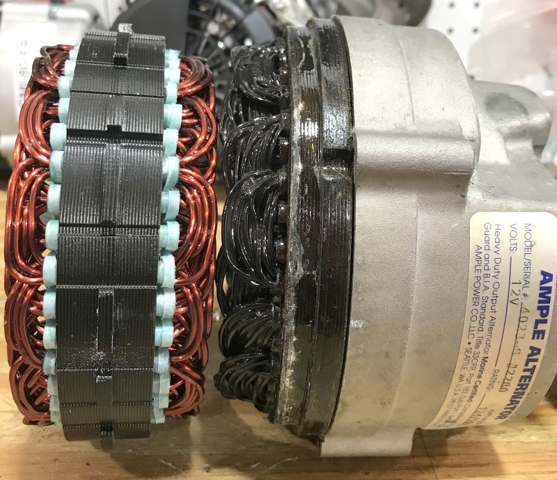
I think I still have one of those Hitachi alternators, the original, gold-painted one that came with my Universal M25. Anyone need one?With the old Hitachi alternators the thermistors could only back off the voltage so much. If the LFP bank was not yet at that backed off voltage smoke goes the alternator...
I also have a spare 100A automotive alternator that I converted to P-type and external regulation, and into which I installed new bearings. I had it as a spare on the C-36, when I was paranoid.
")
My current unit is a Powermax 125A unit, with a Balmar serpentine belt kit, and a turnbuckle-style alternator adjustment arm that I fashioned myself. I can pump 100A indefinitely at the temps reached in my engine compartment. I have an exterenal regulator, of course, and can soft start it as well as limit the output current, which is nice.
Which brings up another interesting topic. What happens when you have a really low impedance load like an LFP bank that needs to be charged at 14.4V or so, and you start limiting current so that the output voltage of the alternator drops below the target charging voltage? Will the bank absorb any charge with the alternator output voltage just marginally above the bank resting voltage?
Of course, for "my design" system I'd want to keep the alternator connected to the LFP bank yet run the house loads when motoring, or even at anchor if I just didn't want to deplete the house bank (for whatever reason, like hair dryers, toasters, etc.), but not over-charge the LFP bank - so control the output to the LFP bank resting voltage. Make sense?
I've been very active with our C34 forum since 1999. Almost all of our boats came with M25 series engines, as did the Catalina 36. As far as I know all of those alternators were Motorolas, not Hitachis. Hitachis came with Yanmar engines and until relatively recently were not present on Catalinas as a normal course of events. Gerry Douglas switched to Yanmars when they started making the 5 series boats, IIRC.I think I still have one of those Hitachi alternators, the original, gold-painted one that came with my Universal M25.
Oh, O.K., maybe it's a Motorola - my recollection could be faulty. I'll look in the basement for it when I get a chance!I've been very active with our C34 forum since 1999. Almost all of our boats came with M25 series engines, as did the Catalina 36. As far as I know all of those alternators were Motorolas, not Hitachis. Hitachis came with Yanmar engines and until relatively recently were not present on Catalinas as a normal course of events. Gerry Douglas switched to Yanmars when they started making the 5 series boats, IIRC.
Jviss, you said “If you can pump sufficient field current it will put out as many amps as necessary to come into regulation, to the point that amperage will exceed the rating” You are losing site of input vs output. While it is true that increasing the current through the windings increases the magnetic field, the current is the result and not the cause. You cannot pump current into the field. The field is pure ohms law. V=Ir. There is a fixed resistance in the windings and the current is dependent on the voltage you put into it which is why I said output is dependent on field voltage. Your regulator does not send current, it regulates the voltage from full battery voltage which results in max current down to 0 volts at which point the current stops and the alternator puts out nothing. The limit to the max output as I stated is the rpm’s and the full battery voltage.
The output of the alternator is not based on Ohms law (v=Ir), it is based on the power equation (P=Iv). You put in power from the engine (hp) and take out power from the output wires (W). The regulator uses Ohms law to control the output of the alternator by reducing the voltage supplied to the windings and thereby limiting the current output. Fun fact, 1 horsepower = 745.7Watts. They are both units that describe power. That means that it takes about 2 hp (plus losses and inefficiencies) to spin that 125A alternator.
(jviss) “Which brings up another interesting topic. What happens when you have a really low impedance load like an LFP bank that needs to be charged at 14.4V or so, and you start limiting current so that the output voltage of the alternator drops below the target charging voltage? Will the bank absorb any charge with the alternator output voltage just marginally above the bank resting voltage?”
An LFP has low internal resistance. The definition of Impedance is
impedance: [imˈpēdns]: NOUN: the effective resistance of an electric circuit or component to alternating current, arising from the combined effects of ohmic resistance and reactance.
Given that we are talking about alternators, the alternator will have internal impedance within the alternating current of the stator/rotor but once it is rectified to direct current impedance is left behind and now, we are only concerned about resistance. A battery is a direct current devise and has internal resistance. It does not have low impedance.
Here again, you are looking at this problem from the viewpoint of ohms law, but the alternator is putting out power which to write it in another way is (ohms law) IR times current. P= IR x I (resistance x current squared). We all talk about the “voltage regulator” but that is in reality another incorrect name based on cause and effect. Voltage is not regulated (caused) by the regulator, it is the result of controlling the current which limits the voltage to a set point (effected). Let’s say that the regulator is set to not allow the voltage to rise above 14.0v. If it senses that the voltage is below 14v, it sends battery voltage to the field windings which creates max current possible in the windings which causes the alternator to put out as much current as its construction can produce at the current rpm’s. Once the regulator senses 14v, it will regulate the alternator (cause) to limit the current output to below what it is capable of generating by reducing the voltage in the field wire which will reduce the current in the windings which in turn reduces the current output of the alternator. This reduction in the current going into the battery will limit the voltage in the battery based on our friend Ohms law.
So to answer your question, if you are trying to limit the output of your alternator to reduce how hot it is running you need to reduce the voltage in the field wire to some level below battery voltage. This is done by increasing the resistance to the field wire such as by adding a rheostat so that you can turn it down. The regulator will still work because it will reduce the voltage sent to the rheostat as the battery voltage hits your set 14.0v but it will get there slower because you are sending fewer amp to it to begin with.
Marketing is all aimed at the end user who typically does not want to know the minutia about how something is done (cause), they just want to know what you did (effect).
My Physics prof told us “Everything you need to know about direct current is contained in four simple letters. PVIR. The hard part in in knowing how to apply them.” Here is a good set of all 12 formulas.
This is either a complete misunderstanding of how this works, or just poor or ambiguous communication. You seem to be conflating field current and output current. Field current is rather small, is used to create the magnetic flux that cuts the stator windings as the field (wound on the rotor) rotates within. The output current is from the stator, through the diodes and is a function of the load impedance (yes, impedance!) and the output voltage. Regulators are designed to control the field current to regulate the alternator output voltage.Jviss, you said “If you can pump sufficient field current it will put out as many amps as necessary to come into regulation, to the point that amperage will exceed the rating” You are losing site of input vs output. While it is true that increasing the current through the windings increases the magnetic field, the current is the result and not the cause. You cannot pump current into the field. The field is pure ohms law. V=Ir. There is a fixed resistance in the windings and the current is dependent on the voltage you put into it which is why I said output is dependent on field voltage. Your regulator does not send current, it regulates the voltage from full battery voltage which results in max current down to 0 volts at which point the current stops and the alternator puts out nothing. The limit to the max output as I stated is the rpm’s and the full battery voltage.
More nonsense. LA batteries have a rather complicated impedance that changes as the SOC changes. See this paper:Given that we are talking about alternators, the alternator will have internal impedance within the alternating current of the stator/rotor but once it is rectified to direct current impedance is left behind and now, we are only concerned about resistance. A battery is a direct current devise and has internal resistance. It does not have low impedance.
Generalized Lead-Acid based Battery Model used for a Battery Management System
Here's the equivalent circuit diagram for a lead acid battery the author developed:
I give up, @Hayden Watson , the above is just gobbledygook.Here again, you are looking at this problem from the viewpoint of ohms law, but the alternator is putting out power which to write it in another way is (ohms law) IR times current. P= IR x I (resistance x current squared). We all talk about the “voltage regulator” but that is in reality another incorrect name based on cause and effect. Voltage is not regulated (caused) by the regulator, it is the result of controlling the current which limits the voltage to a set point (effected). Let’s say that the regulator is set to not allow the voltage to rise above 14.0v. If it senses that the voltage is below 14v, it sends battery voltage to the field windings which creates max current possible in the windings which causes the alternator to put out as much current as its construction can produce at the current rpm’s. Once the regulator senses 14v, it will regulate the alternator (cause) to limit the current output to below what it is capable of generating by reducing the voltage in the field wire which will reduce the current in the windings which in turn reduces the current output of the alternator. This reduction in the current going into the battery will limit the voltage in the battery based on our friend Ohms law.
Last edited:
Maybe I'll start a thread called "How Do Alternators Work?" And also "How Do Voltage Regulators Work?"
I apologize for letting this thread wander from LFP technology, but then, I started the thread, so the only OP I may have upset is me!
One of the infuriating things is when you discuss things here in conventional terms and someone starts arguing with you, for example, using Ohm's law to say "it's not the current, it's the voltage!" Well, duh.
I'd like to see one alternator specification that rates it in terms of maximum power instead of current-RPM-temp. And, I'd like to see that magical, constant power alternator!
Good luck with that with LFP..My current unit is a Powermax 125A unit, with a Balmar serpentine belt kit, and a turnbuckle-style alternator adjustment arm that I fashioned myself. I can pump 100A indefinitely at the temps reached in my engine compartment. I have an exterenal regulator, of course, and can soft start it as well as limit the output current, which is nice.
The PM is built to the same standard as the old Ample alt...We built a similar version only much improved over where Ample left off.... We were using the best quality magnet wire USA wound stators & rotors, 75A 400V diodes vs. 50A 200V. We used the same quality diodes used in massive 300A ambulance alternators. We also improved the heat sinking and used a bronze B+ bolt which also helped to minimize localized heating. Ample made the outlandish claim that these alts were constant duty (before AGM and LFP hit the scene)..When LFP came along.... Smoke....
Even on our AMP-IT HD125ER we would never suggest 100A continuously into LFP...
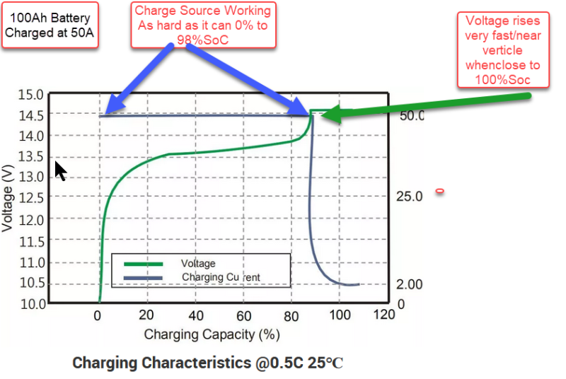
For someone who continually talks down to everyone on this forum about anything electrical, I am amazed by this statement from you?The alternator connected to LFP will be at battery voltage while the current slowly increases SoC and voltage from about 0% SoC to almost 98% SoC.finally at the very very end of the charge cycle the voltage will rise rapidly to the absorb voltage and current will decline rapidly. The blue line below is what is often referred to is constant-current or bulk charge . An Alternator is not actually constant-current like, a charger would be, I prefer to call it constant potential because it cannot be constant-current due to RPM and such so it is the constant potential of the alt based on RPM ambient temperature, copper temp etc.. At any point below the target voltage the alternator will be working as hard is it can & the regulator will be driving the field at 100% unless the temp sensor tells it to back off on the field to let the alt cool... This is why it is critical to have a temperature sensor to protect the alternator when charging lithium iron phosphate batteries.Just because an alternator is striving to get to 14.4 V does not mean that happens immediately. It cannot due to the large stubborn load that it is trying to charge. At a .5C charge-rate the alternator is at battery voltage until about 98%SoC. Once the battery voltage finally hits absorption the absorption duration needs to be short typically, 2 minutes to 30 minutes ..Which brings up another interesting topic. What happens when you have a really low impedance load like an LFP bank that needs to be charged at 14.4V or so, and you start limiting current so that the output voltage of the alternator drops below the target charging voltage? Will the bank absorb any charge with the alternator output voltage just marginally above the bank resting voltage?
Then get a Wakespeed WS-500Of course, for "my design" system I'd want to keep the alternator connected to the LFP bank yet run the house loads when motoring, or even at anchor if I just didn't want to deplete the house bank (for whatever reason, like hair dryers, toasters, etc.), but not over-charge the LFP bank - so control the output to the LFP bank resting voltage. Make sense?
Actually they all do....
I'd like to see one alternator specification that rates it in terms of maximum power instead of current-RPM-temp. And, I'd like to see that magical, constant power alternator!
Some do it directly such as all of the inverter generators like the Honda EU2200i. In the specs they tell you that it is 2200W starting and 1800W continuous. They then translate that through the power equation P=IV to 18.3A @ 120 starting and 15A @ 120 continuous. [I will assume that you will call foul and say this is a different animal but it is not. All inverter generators are a fuel powered engine that uses the rotational mechanical power (hp) of and fuel powered engine to turn and alternator that converts it first to AC electrical power (watts) and then rectifies it to DC electrical power (watts) before running it through an inverter that converts the DC back to AC at a regulated 120v.
Some do it indirectly. For some reason that I cannot understand or guess at, the automotive and marine alternator market has chosen to rate their power output indirectly by the "IV" side of power equation P=IV. They list the power of the power generating device called an alternator as 125A @ 12-volts which when written as a mathematical equations would be 125A x 12v which my calculator tells me is "1500Amp-volts" but per the rules of unit conversion should be simplified to 1500-watts.
BTW when was the last time that you heard of a power generation station such as being rated by their amp capacity. Never seen a mega-Amp rating but see lots of reference to megawatt generators. Electrical power is measured in watts and that cannot change. If you prefer to examine your watts of power based on the number of amps you get at a specific voltage that is fine but it does not change the fact that what we are talking about is watts of power. Personally, when I am looking at solar devices which are always rated in watts, the first thing I do is to find out what that will "do" for me by finding out how many amps I can put into my battery so I divide the watt rating by 13.6v (an average charge current) to get the maximum amps that it will deliver to the battery during charging.
It wasn't a statement, it was a question. I guess I didn't ask clearly enough. Let me try again.For someone who continually talks down to everyone on this forum about anything electrical, I am amazed by this statement from you?
Let's say the LFP is at 20% SOC, but, owing to the fairly flat voltage discharge characteristic, it's at 13.5V. So, in order to drive charge into the bank, my understanding is you want to drive the alternator to 14.5V or so (could be wrong). So, you set the regulator for 14.5V, but because of the size fo the bank, the low impedance of LFP, etc., the current exceeds your current limit setting for the regulator. To reduce current, the regulator decreases the AO voltage. Then what happens? Can the regulator settle to a point where the batteries are still charging, but the output current is not exceeded? I assume this will be leas than the 14.5?. Will the LFP bank charge at a lower voltage than that?