Wiring Diagram for Lithium Ion installation

Jan 11, 2014
14,115
Sabre 362 113 Fair Haven, NY
Thanks @dlochner for the tip on BEP Pro installer.

I actually don't have the Epoch but rather a WattCycle 314AH Mini as recommended by @Maine Sail. My wiring scheme is set up to avoid potentially large "in-rush" current which, as described by Rod as potential problems for the BMS system of Lithium battery banks. This places the loads with the potential for "in rush" current onto the Start Battery. In particular the "in-rush" is not the same as "continuous" or even the "peak discharge current." The in-rush current last only for less than a second but can play heck on the BMS system. Here is the link to his discussion. Hopefully @Maine Sail will comment not only on the proposed diagram, but the topic of in-rush current. Maybe I'm overly concerned with this.

The following exerpts are from Rod's primer on Drop-In Lithium batteries and considerations in their proper care and use.
______________________________________________________________________________________________________________________________________________---
From:
Drop-In LiFePo4- Be an Educated Consumer

DC Motor In-rush

The reason most drop in batteries cannot be used for starting is the in-rush current. The in-rush of large DC motors looks like a dead short to the FET’s. Imagine sitting there and intentionally shorting your battery multiple times each day…..That is what starting your motor, running a windlass, electric winch or Bow thruster looks like to the FET’s. There are LFP batteries that can be used for starting but they are very expensive at this point in time.

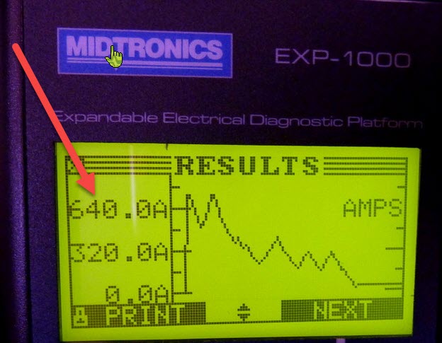
Starting a 40HP Westerkeke takes=640A!!!!


Know your loads before you buy!

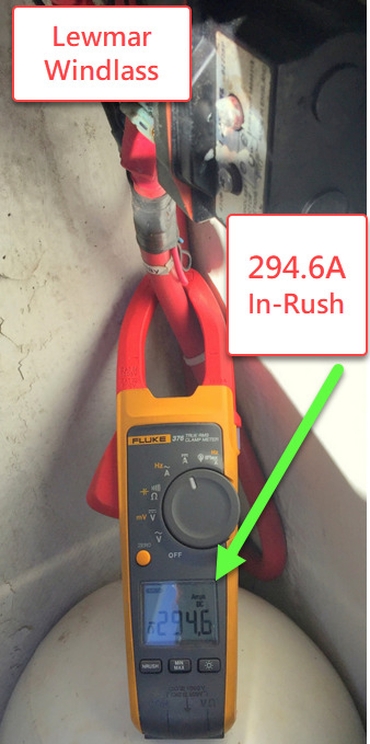
The critical load data you need to know is the in-rush current for all DC Motors .This includes a windlass, electric winches or a bow thruster. You also want know your inverters Pre-charge in-rush. Unfortunately most DC Clamp meters cannot properly capture DC in-rush current. We own three DC clamp meters that claim to do in-rush but all except the Fluke meters fail miserably. The image below is one of our Fluke 376 meters capturing the in-rush current for a Lewmar V2 Windlass. This customer ruined his FET BMS (seen in an image above in this article) by using his “direct from China” drop-in battery to power his windlass. Warranty? Ha-ha now that’s funny….


The image above is a prime example of how drop-in battery bank went wrong for this customer. he wanted to lighten the load in the bow of his sailboat so he installed a single drop-in battery to power his windlass.What he failed to understand was the BMS’s current handling rating . In just a few short weeks he destroyed his drop-in battery with his windlass when he failed to account for what the peak in-rush current handling of the BMS., Warranty? Not covered!
I'm not going to argue with Rod. The issue is the margin of safety. I use the house bank for the windlass (don't have electric winches). The 3 batteries each have a max current surge (peak) discharge of 350a (3 seconds) for a total of 1050a. The inrush for the windlass is well below that threshold. Additionally, my alternator feeds the house bank and is typically running when the windlass is used providing an additional ~80a of current.

In your case, because the alternator feeds the start battery it is better to use that battery for the windlass and winch. If I were to have that arrangement on my boat, I would have a large start battery because the drain on the battery will be relatively high and recharging with the Hitachi alternator will be slow. (See Rod's article on Automotive alternators.) In particular a small AGM battery could easily be left in a partial state of charge for longer periods of time which is fatal for those batteries. FLA batteries would only fair slightly better.

Wattcycle does not provide a Max surge (peak, instantaneous) discharge rating for the 314ah batteries. As a result, using them for a windlass or winch might risk the kind of damage to the BMS that Rod mentions, but we don't know because WC didn't specify the max surge current. Bear this in mind if you should find yourself in the position of having to run everything off the house battery due to a start battery failure.
 
Feb 26, 2004
23,450
Catalina 34 224 Maple Bay, BC, Canada
(See Rod's article on Automotive alternators.)
Here is the text of Maine Sail's article:

Hitachi/Yanmar Alternators: (by Maine Sail)

Some alternators though, such as those made by Hitachi and found on Yanmar diesels, are dumber than a pound of beetle poop. Actually, to the alternator, they are pretty smart but to your batteries and the speed of charging they are flat out stupid. Why?

Hitachi alts with dumb regulators, and some others, limit voltage but also reduce voltage based on alternator temperature. This is a self protective feature installed in the internal dumb regulator to prevent the alternator from cooking itself. Remember voltage is the pressure that allows more current to flow. So, if we reduce the absorption voltage, then we also reduce the current the alternator is supplying.. Any battery at any state of charge simply will not accept the same current at 13.4V that it did at 14.4V and as a result the alternator will run cooler. What do you suppose this does to your batteries over time.......?

The problem is that when cold you will get 14.3V to 14.4V out of the Hitachi but as the alternator heats up the dumb regulator begins to reduce the CV/voltage limit based on the alternators internal temperature. It is not uncommon to find a Hitachi alternator at 13.4V when hot. This is REALLY, REALLY DUMB....

If you have a dumb regulator, and notice the voltage dropping, it is likely a temp compensated dumb regulator. Get rid of it or plan to buy new batteries more often.

If you have a temp compensated alternator or a Hitachi alternator on a Yanmar you really are in dire need of external regulation if deep cycling a larger battery bank.

This is from:

http://forums.sbo.sailboatowners.com/showthread.php?t=125392

and these, too:

http://www.cruisersforum.com/forums...d-smart-regulator-instal-question-125843.html

http://www.cruisersforum.com/forums/f14/most-practical-way-to-upgrade-yanmar-alternator-142083.html
 
  • Helpful
Likes: jssailem

Johann

.
Jun 3, 2004
579
Leopard 39 Pensacola
Victron XS DC -DC 50 A
Hitachi 80 A
I have been using the old Victron 30A Orion Tr Smart with the Hitachi 80A in a similar configuration to your proposal for about 5 years. My Orions are much less efficient than yours but with cooling fans I can sustain 30-32A output with the Hitachi inputing 38-40A. So I think you will be fine with a 40A output setting on your Orion XS. Also you can monitor the input voltage to the Orion from the Hitachi. Mine will stabilize around 13.4V on a long motoring run at full output from the Orion.
 
  • Helpful
Likes: jssailem
Jan 11, 2014
14,115
Sabre 362 113 Fair Haven, NY
For those who like to peruse wiring schematics - I'm not one who does - Wooden Boat Magazine's current issue has what must be the Mother of All schematics. It is in an article about the electric refit of a classic wooden sailboat. To say the author went to town would be an understatement. But that's not criticism really. I'm just struct by the complexity of the project. I'd post a pic but I think that might be a violation of some sort.
@shemandr to paraphrase a common expression, "Complexity is in the eye of the beholder." I know the author of that article pretty well, we've been working together on a project for the past couple of years, this was one of his simpler jobs and simpler schematics.

It takes some time to learn to read schematics and some guidance on how to do it. One aspect of the schematic in the WB article is the inclusion of the communication cables. These are in blue, ignoring them and only looking at the red lines the schematic becomes much easier to understand. Next pick a function, say charging, look for the charging sources, in this case the Victron Multiplus, alternator, and solar panels. follow the red lines to see where they go. In this case they all go to the "Power Distribution" box (Victron's fancy name for a DC+ bus) and the DC panel is connected there too. As you trace each line you can begin to see the relationship between each of the parts.
Screenshot 2026-09-08 at 9.34.48 PM.png

I've also attached another schematic Don drew. This is considerably more complex covering 5 pages.

The article in Wooden Boat is a great introductory article for anyone considering a LFP installation. The article goes through each part of the system and explains what it does and why it is important. Wooden Boat Magazine does sell individual digital copies of its magazine. This article is worth the $7.50 if you are interested in the subject. It is in the Sept/Oct 2026 issue.


Attachments

Feb 6, 1998
11,765
Canadian Sailcraft 36T Casco Bay, ME
Here is the text of Maine Sail's article:

Hitachi/Yanmar Alternators: (by Maine Sail)

Some alternators though, such as those made by Hitachi and found on Yanmar diesels, are dumber than a pound of beetle poop. Actually, to the alternator, they are pretty smart but to your batteries and the speed of charging they are flat out stupid. Why?

Hitachi alts with dumb regulators, and some others, limit voltage but also reduce voltage based on alternator temperature. This is a self protective feature installed in the internal dumb regulator to prevent the alternator from cooking itself. Remember voltage is the pressure that allows more current to flow. So, if we reduce the absorption voltage, then we also reduce the current the alternator is supplying.. Any battery at any state of charge simply will not accept the same current at 13.4V that it did at 14.4V and as a result the alternator will run cooler. What do you suppose this does to your batteries over time.......?

The problem is that when cold you will get 14.3V to 14.4V out of the Hitachi but as the alternator heats up the dumb regulator begins to reduce the CV/voltage limit based on the alternators internal temperature. It is not uncommon to find a Hitachi alternator at 13.4V when hot. This is REALLY, REALLY DUMB....

If you have a dumb regulator, and notice the voltage dropping, it is likely a temp compensated dumb regulator. Get rid of it or plan to buy new batteries more often.

If you have a temp compensated alternator or a Hitachi alternator on a Yanmar you really are in dire need of external regulation if deep cycling a larger battery bank.

This is from:

http://forums.sbo.sailboatowners.com/showthread.php?t=125392

and these, too:

http://www.cruisersforum.com/forums...d-smart-regulator-instal-question-125843.html

http://www.cruisersforum.com/forums/f14/most-practical-way-to-upgrade-yanmar-alternator-142083.html
That article was written with lead acid as the primary focus where voltage reductions in absorption can have battery destroying outcomes. For LFP the voltage thermal based voltage reduction can help to protect the alt from heat damage. LFP can achieve 100% SoC at jut 13.8V so, even with these thermal reductions the batts can still achieve 97-100% SoC.
 
  • Like
Likes: Stu Jackson