Repairing Hunter 40 damage from Hurricane Matthew
- Thread starter B757Captain
- Start date
Aaaaannnd, we're back!:
Ok, picture hosting back up so here we go!
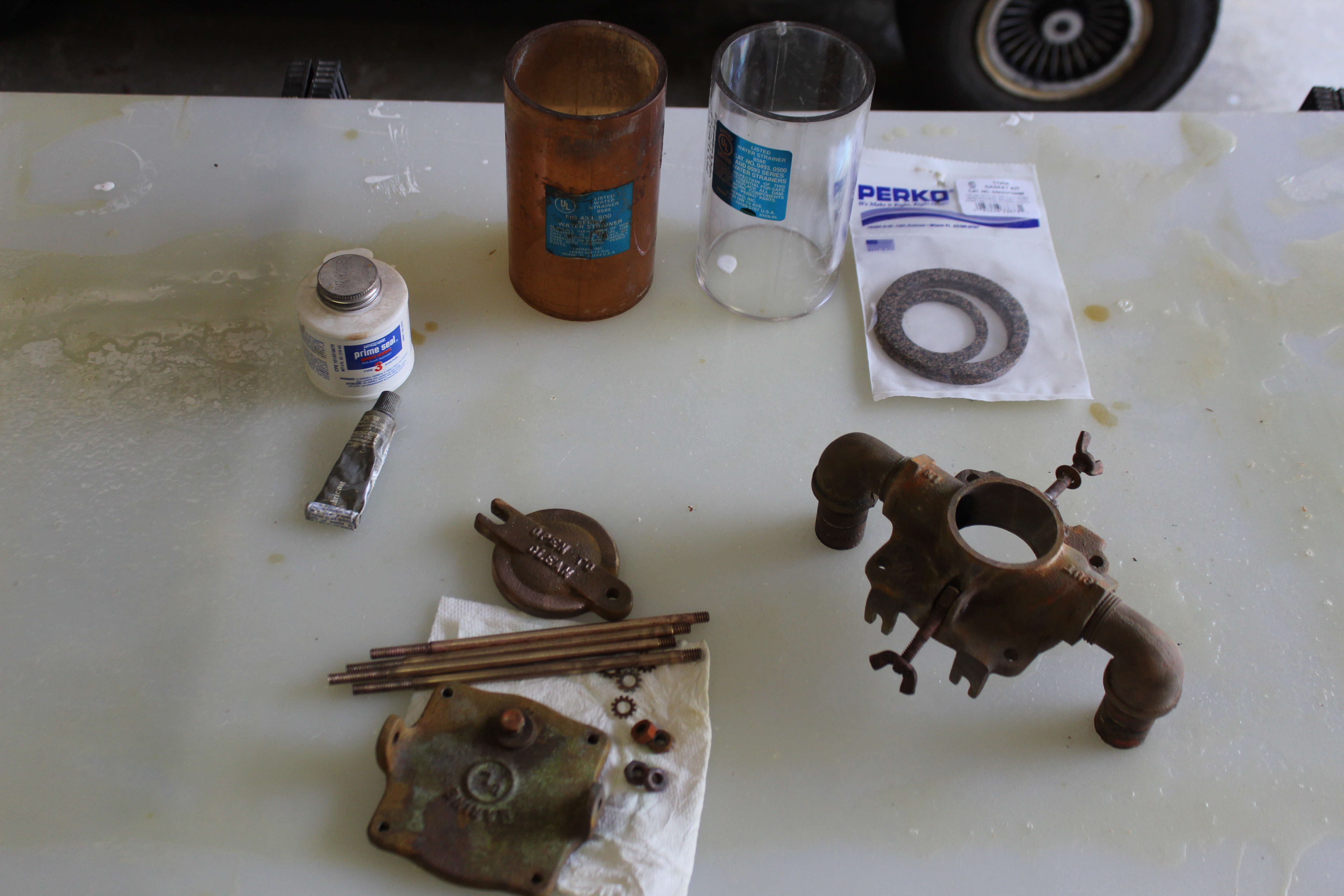
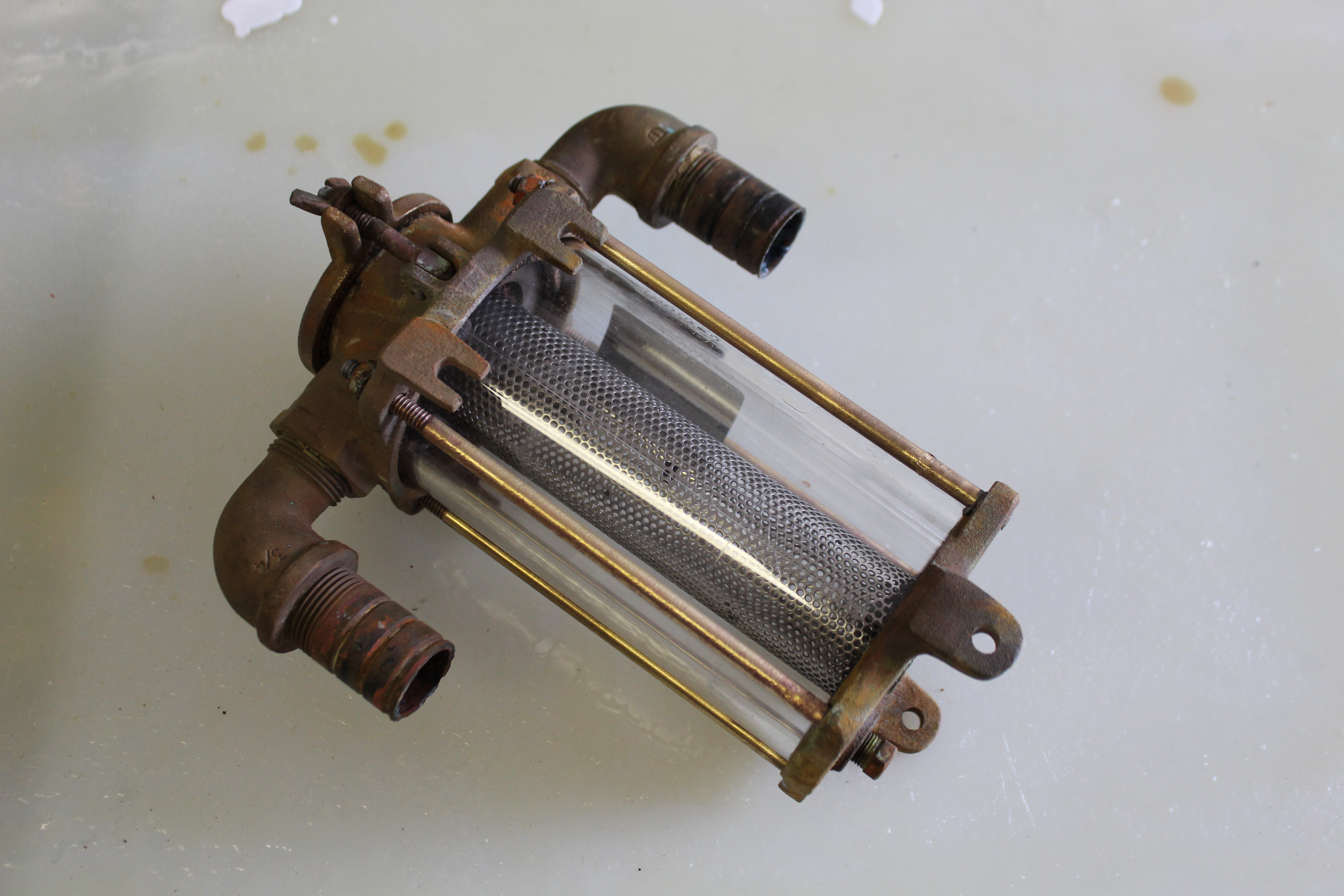
I spent some evening time rebuilding the raw water strainers - not because I need them right now but because I'm trying to de-clutter the parts pile a little bit. One of the strainers needed a new glass because the original has become really opaque. I learned a small tidbit about the Perko 0493 series strainers if anyone else needs to service them - Perko lists two service kits, one for cork gaskets and one for rubber. I have one of each, probably because the engine strainer likely is original (cork) and the a/c strainer (rubber) was added by me. I wasn't able to get a kit with rubber gaskets (out of stock) but got the cork ones. Turns out the castings are identical so either kit will work in a pinch. That being said I am rebuilding them to (1) replace the glass and (2) since I'm doing one, might as well do the other - not because they need it. Everything came apart very easily and cleanup was straight-forward (though I have access to a blast cabinet for cleanup the sand was all used up so I soaked everything in white vinegar instead):
And here it is mounted:
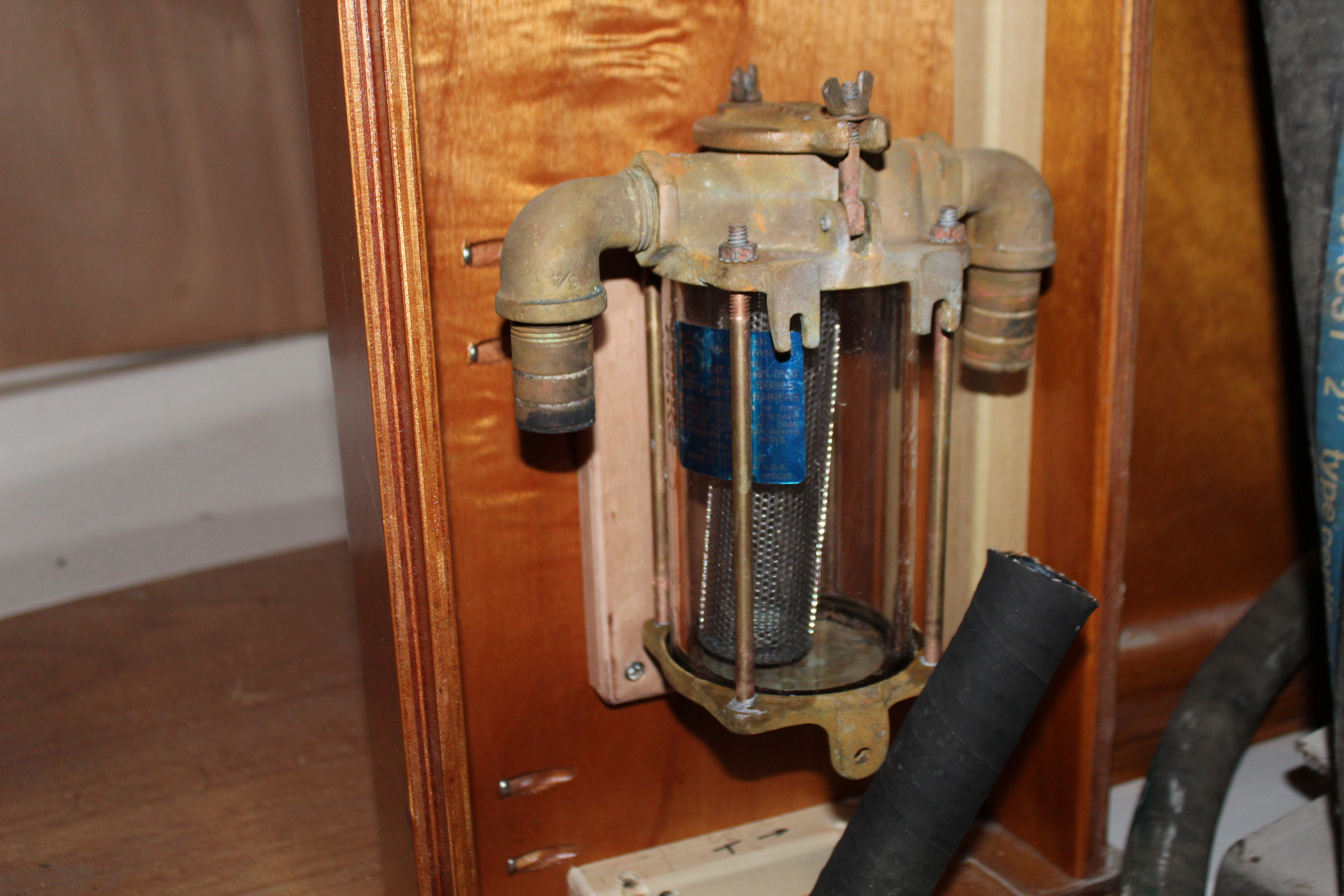
I didn't pay enough attention to the flow arrow so I got the label on the glass in the wrong place. Will adjust that at some time . I can't seem to find my container of hose clamps so couldn't hook up the hoses just yet.
Next up was continuing up in the v-berth. I cut and fitted the remaining cabinet face under the bunk and cut the openings:
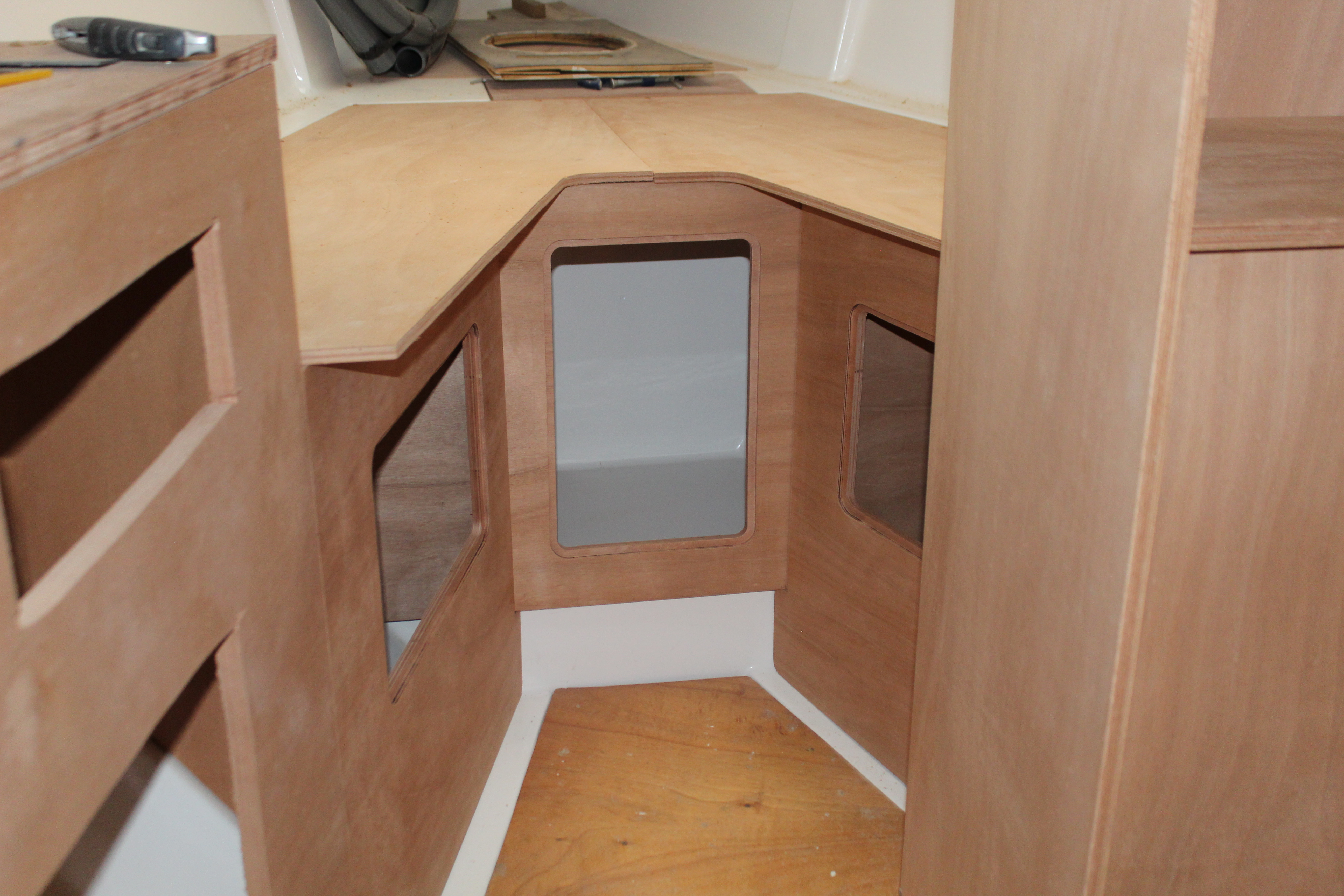
I'm not planning on adding shelves inside the side lockers but I'll put a shelf in the front. Also thinking of adding openings with covers through the bunk to access the forward locker from above.
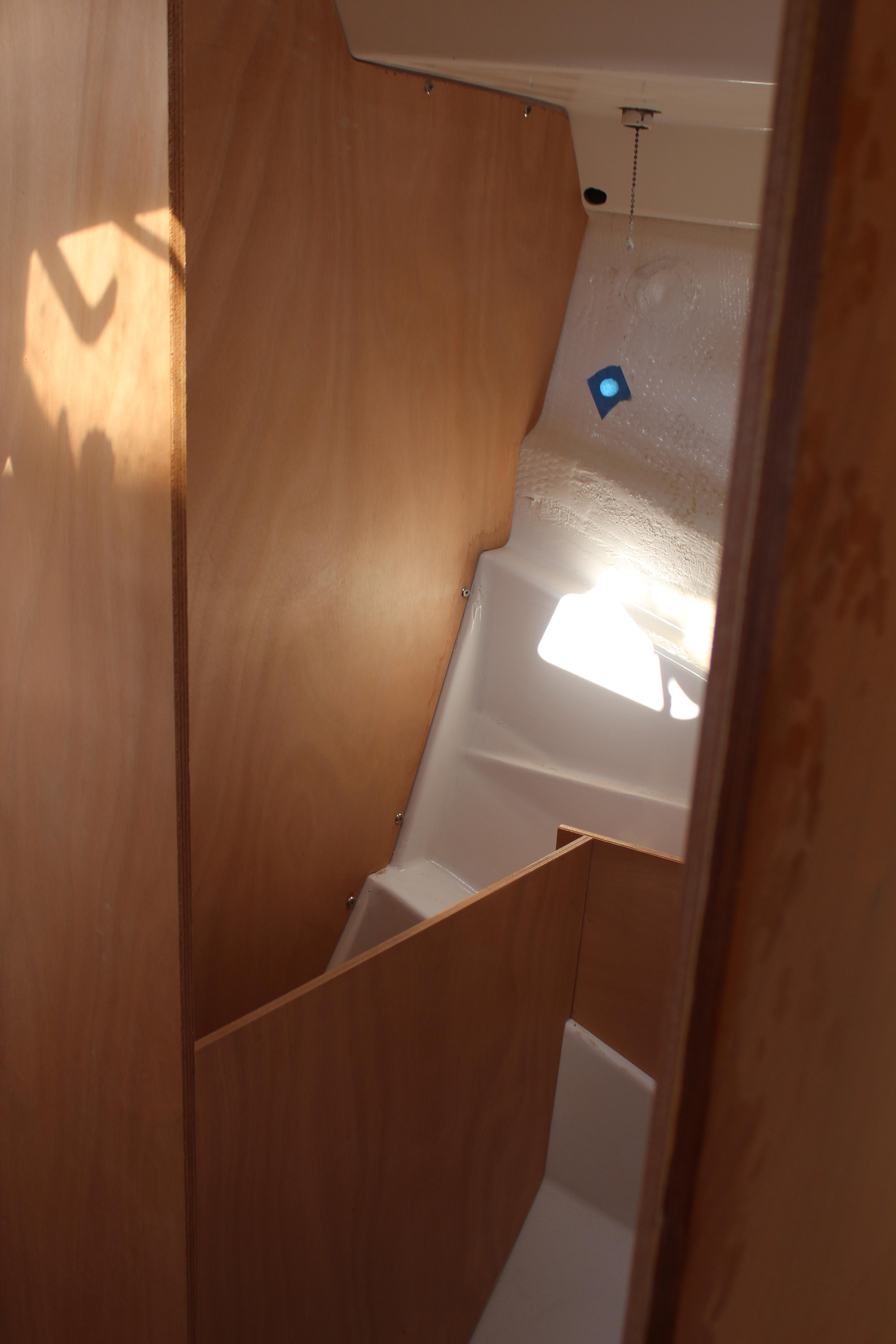
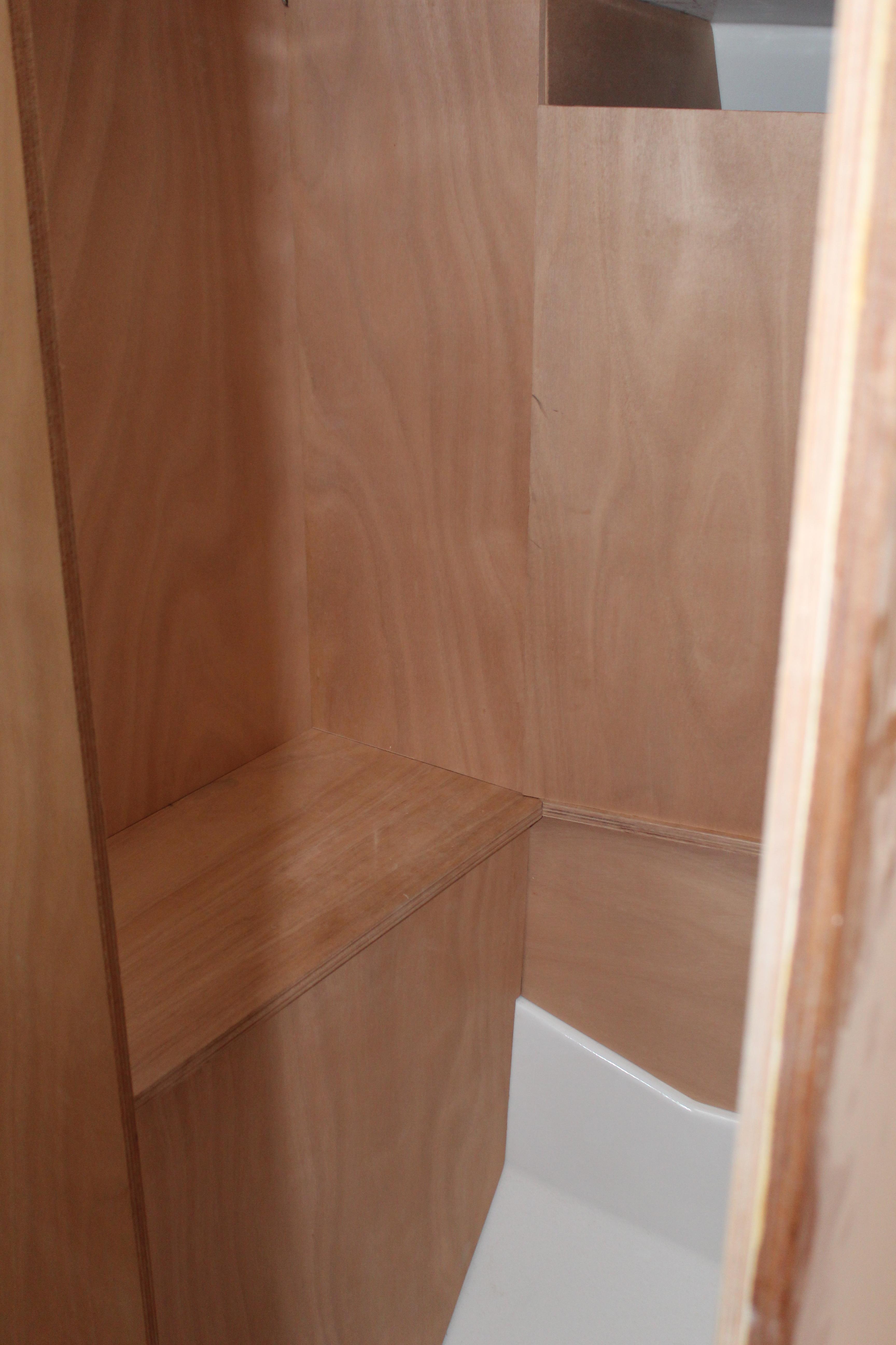
I started framing up the parts and pieces for the forward head. Due to the weird angles trying to get good photos of the head is pretty much impossible but I got the vertical bulkhead cut and fitted and cabinet faces:
Next the countertop and upper cabinet faces. It will look more presentable with the openings cut (I'm working on the templates now):
I seem to have good luck with weird premonitions and though nothing has been said officially, I have a suspicion SC is going to be under lockdown by the end of this week or beginning of next.The admiral and I topped off our supplies (no TP, already had plenty ) but I did stock up on Captain Morgan so we're good! I've got a few things being shipped but even if boating supplies can't make it through I still have materials-o-plenty to keep me going for quite a while so work and updates will continue!
Cheers,
Mark
Ok, picture hosting back up so here we go!
I spent some evening time rebuilding the raw water strainers - not because I need them right now but because I'm trying to de-clutter the parts pile a little bit. One of the strainers needed a new glass because the original has become really opaque. I learned a small tidbit about the Perko 0493 series strainers if anyone else needs to service them - Perko lists two service kits, one for cork gaskets and one for rubber. I have one of each, probably because the engine strainer likely is original (cork) and the a/c strainer (rubber) was added by me. I wasn't able to get a kit with rubber gaskets (out of stock) but got the cork ones. Turns out the castings are identical so either kit will work in a pinch. That being said I am rebuilding them to (1) replace the glass and (2) since I'm doing one, might as well do the other - not because they need it. Everything came apart very easily and cleanup was straight-forward (though I have access to a blast cabinet for cleanup the sand was all used up so I soaked everything in white vinegar instead):
And here it is mounted:
I didn't pay enough attention to the flow arrow so I got the label on the glass in the wrong place. Will adjust that at some time
. I can't seem to find my container of hose clamps so couldn't hook up the hoses just yet.Next up was continuing up in the v-berth. I cut and fitted the remaining cabinet face under the bunk and cut the openings:
I'm not planning on adding shelves inside the side lockers but I'll put a shelf in the front. Also thinking of adding openings with covers through the bunk to access the forward locker from above.
I started framing up the parts and pieces for the forward head. Due to the weird angles trying to get good photos of the head is pretty much impossible but I got the vertical bulkhead cut and fitted and cabinet faces:
Next the countertop and upper cabinet faces. It will look more presentable with the openings cut (I'm working on the templates now
):
I seem to have good luck with weird premonitions and though nothing has been said officially, I have a suspicion SC is going to be under lockdown by the end of this week or beginning of next.The admiral and I topped off our supplies (no TP, already had plenty
) but I did stock up on Captain Morgan so we're good! I've got a few things being shipped but even if boating supplies can't make it through I still have materials-o-plenty to keep me going for quite a while so work and updates will continue!Cheers,
Mark
very nice ! thanks a lot Captain, I've a Hunter 25.5.. your is posts are now a reference
I've got a buddy down the street that has a Glasair II, I fly it whenever I get the urge. Mostly below 1000 ft, looking out the windows and having fun!If you want to fly something go hands on, try bush flying on a DHC 2 or turbo Otter DHC 3 or the new Viking Twin Otter 400 floats, ski or wheels.
When I was working in the Maldives I got to know a lot of the Twotter-on-floats pilots. Looks like fun - I'm game. Never been in a Beaver but - game too!I just watched a fun video about the Beaver
Viking should restart production with the turbo Beaver, although the sound of that old radial...
Welcome aboard!Wow,,, just came across your post...and I thought I had a project ahead of me. I just bought a 85 hunter 40 that was gutted by the PO and then he gave up. Atleast mine was clean and all the demo done. What your doing looks great...
Thanks!very nice ! thanks a lot Captain, I've a Hunter 25.5.. your is posts are now a reference
I know its in one of your earlier post but can you share again wood type your using and thickness? Keep up the great work!
I’d like to chime in here, if I may.My reasoning for going with distributed panels is to reduce the total amount of wiring necessary. With one big panel all wiring must start and end at the panel leading to thick wiring bundles. I plan on one (large gauge) feed wire to each zone from the main panels then branching out from there with shorter wire runs to each item. As it is the only branch panels will be AC and DC for the galley and DC circuit breaker/switch panels, one for the lights and one for the cockpit. The rest will be busbars and switches for aft, main and forward cabins.
I used to keep spare breakers that were rated for both AC and DC, my question/confusion was focused more on the switches. Blue Sea doesn't spell that out very well. I will probably order a few of the switches to decide which ones I want and hopefully the literature for the switches will clarify for me.
Thanks,
Mark
I too, believe that distributed switching (in the way you are considering it), is over-complicating a 40 footer.
If you were to at all consider distributed switching, you’d want to go with solid state canbus remote. This was intended for the architecture you are proposing, but it over-complicates your boat.
You have to weigh off the cost of wiring, ease of installation, versus the necessity to distribute the switching.
As mentioned, breakers protect the wiring.
As your boat is still opened up, doing cable runs is easy. Your lighting will typically be 16 guage (being led), and the other stuff you’ll size according to the published charts.
Now, having said this, I’ve done remote switching on my boat, but for a different reason. I wanted to install a bunch of LED lighting in different cabins, and have control of them either in their own cabin, or anywhere else in the boat.
The solution was wireless remotes in each cabin, which could control any of the cabin light sectors in the boat. This meant wiring this lighting all back to a central switching point, which was a lot of effort. But, it gave local control in all cabins. But there was a defined reason for that.
I know this is not what your intent is. But, I don’t see a huge upside to having the distributed power scheme you are proposing.
Only do something if there are clear benefits that warrant the exercise.
I'm using Okumi marine ply, red oak for the trim and the finish is Minwax clear urethane.I know its in one of your earlier post but can you share again wood type your using and thickness? Keep up the great work!
Thank You!I'm using Okumi marine ply, red oak for the trim and the finish is Minwax clear urethane.
Too late, already bought the panelsI’d like to chime in here, if I may.
I too, believe that distributed switching (in the way you are considering it), is over-complicating a 40 footer.
If you were to at all consider distributed switching, you’d want to go with solid state canbus remote. This was intended for the architecture you are proposing, but it over-complicates your boat.
You have to weigh off the cost of wiring, ease of installation, versus the necessity to distribute the switching.
As mentioned, breakers protect the wiring.
As your boat is still opened up, doing cable runs is easy. Your lighting will typically be 16 guage (being led), and the other stuff you’ll size according to the published charts.
Now, having said this, I’ve done remote switching on my boat, but for a different reason. I wanted to install a bunch of LED lighting in different cabins, and have control of them either in their own cabin, or anywhere else in the boat.
The solution was wireless remotes in each cabin, which could control any of the cabin light sectors in the boat. This meant wiring this lighting all back to a central switching point, which was a lot of effort. But, it gave local control in all cabins. But there was a defined reason for that.
I know this is not what your intent is. But, I don’t see a huge upside to having the distributed power scheme you are proposing.
Only do something if there are clear benefits that warrant the exercise.
I think everyone is over-complicating my intent. Maybe when it comes time to install everything and wire things up it will all make sense. At least, it (may) make sense to me
.Keel/hull Joint:
I'm alternating days working in the cabin and progressing around the hull - sanding prepping for barrier coat and the keel/hull joint. It's really hard on my shoulders and arms with all the overhead sanding work so I try to limit to a few hours at a stretch to prevent making an invalid out of myself.
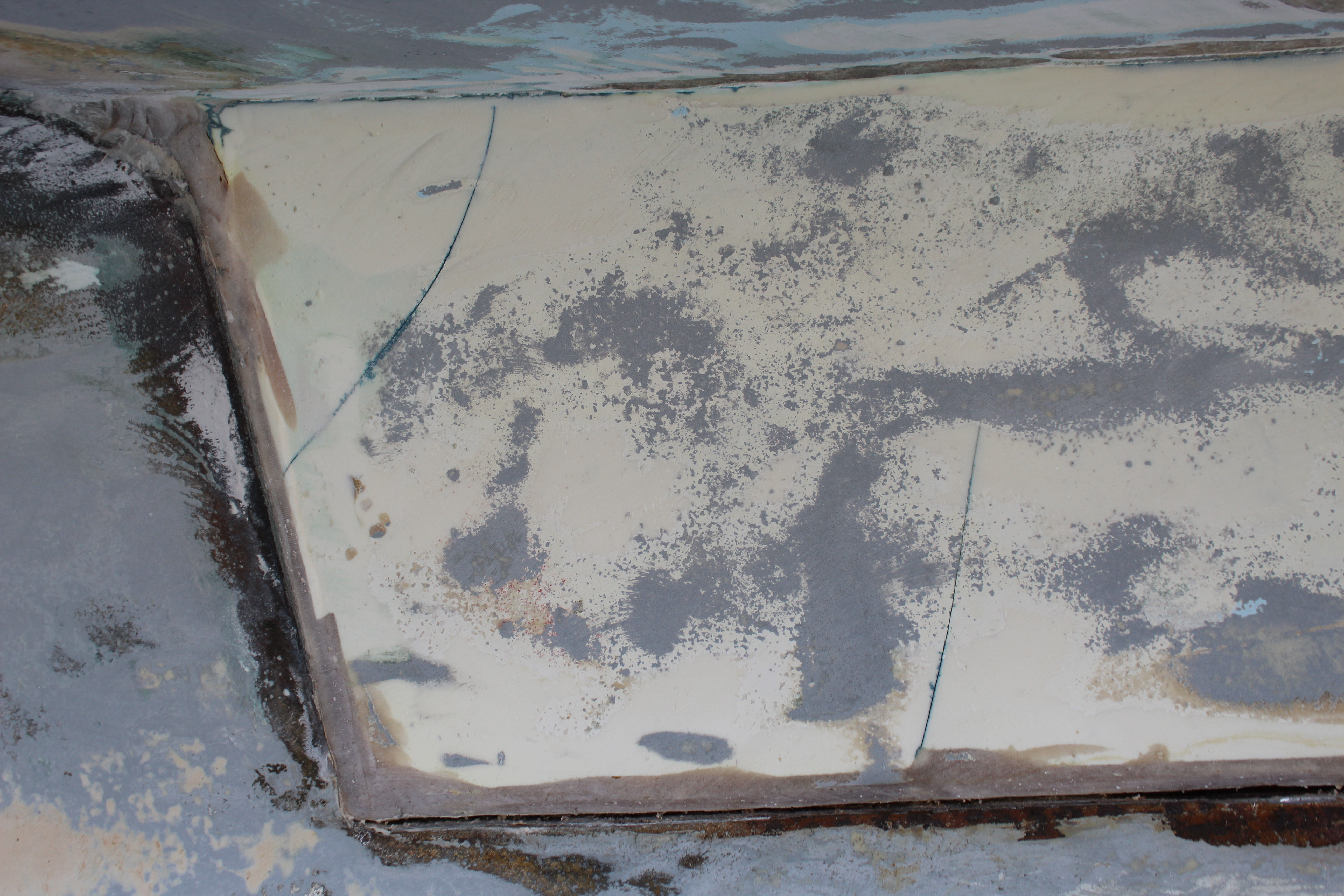
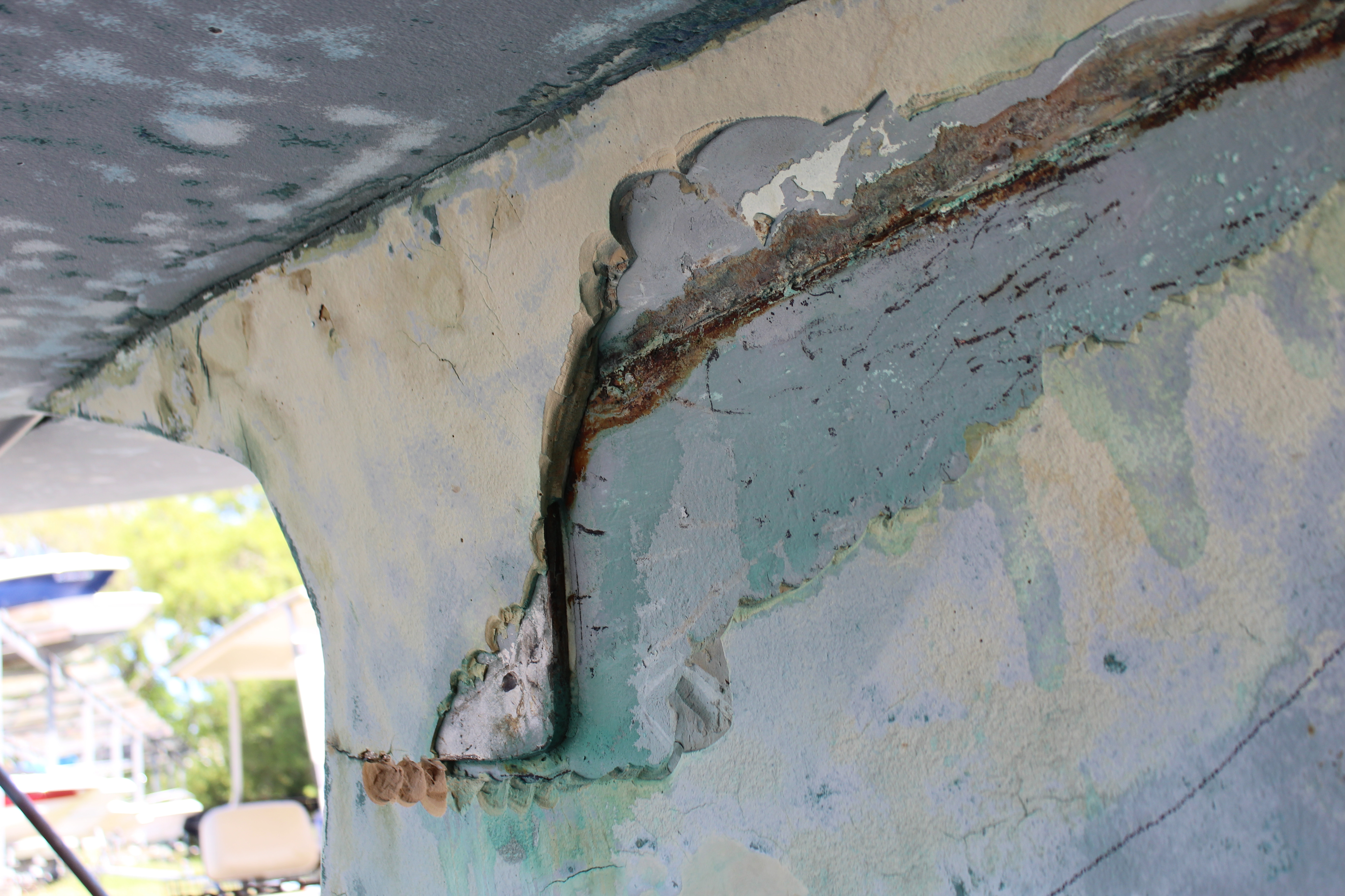
Below-the-waterline work has alternated between sanding and working on the rust spots on the keel/hull joint. At first I thought I had only four or five spots to address, but as we all know, that can go awry! Here's one trouble spot:

It may be hard to see but there are four or five "repairs" in this area alone. As I kept grinding to get to the good parts I found that 1: the previous attempts to fix the rust often overlapped, and this is because 2: the very first underlying fix was a really poor excuse for a repair!
I kept grinding until I got to a good spot but as I kept working the joint it became apparent that there had been many previous attempts all over the joint. It was an easy decision to make - repair the entire joint, so keep on grinding! I have gotten it all ground down (with a big, big surprise along the way! - this will be in the next post, deserves one of it's own .
The good news is that the actual joint is good! I had to resort to several various methods to clean enough 5200 out of the joint to create a groove for the G-flex. Strangely enough though I did have several spots that were "touched up" with butyl tape - I've never heard of that being used for this but it seemed to have worked. The problems with the joint all stem from rust that was not properly treated and sealed. I did find several spots that will need attention before fixing, filling and fairing, like these gelcoat cracks:
Stay tuned for Part Two!
Cheers,
Mark
I'm alternating days working in the cabin and progressing around the hull - sanding prepping for barrier coat and the keel/hull joint. It's really hard on my shoulders and arms with all the overhead sanding work so I try to limit to a few hours at a stretch to prevent making an invalid out of myself
.Below-the-waterline work has alternated between sanding and working on the rust spots on the keel/hull joint. At first I thought I had only four or five spots to address, but as we all know, that can go awry! Here's one trouble spot:
It may be hard to see but there are four or five "repairs" in this area alone. As I kept grinding to get to the good parts I found that 1: the previous attempts to fix the rust often overlapped, and this is because 2: the very first underlying fix was a really poor excuse for a repair!
I kept grinding until I got to a good spot but as I kept working the joint it became apparent that there had been many previous attempts all over the joint. It was an easy decision to make - repair the entire joint, so keep on grinding! I have gotten it all ground down (with a big, big surprise along the way!
- this will be in the next post, deserves one of it's own .The good news is that the actual joint is good! I had to resort to several various methods to clean enough 5200 out of the joint to create a groove for the G-flex. Strangely enough though I did have several spots that were "touched up" with butyl tape - I've never heard of that being used for this but it seemed to have worked. The problems with the joint all stem from rust that was not properly treated and sealed. I did find several spots that will need attention before fixing, filling and fairing, like these gelcoat cracks:
Stay tuned for Part Two!
Cheers,
Mark
Keel/hull joint - the Surprise!:
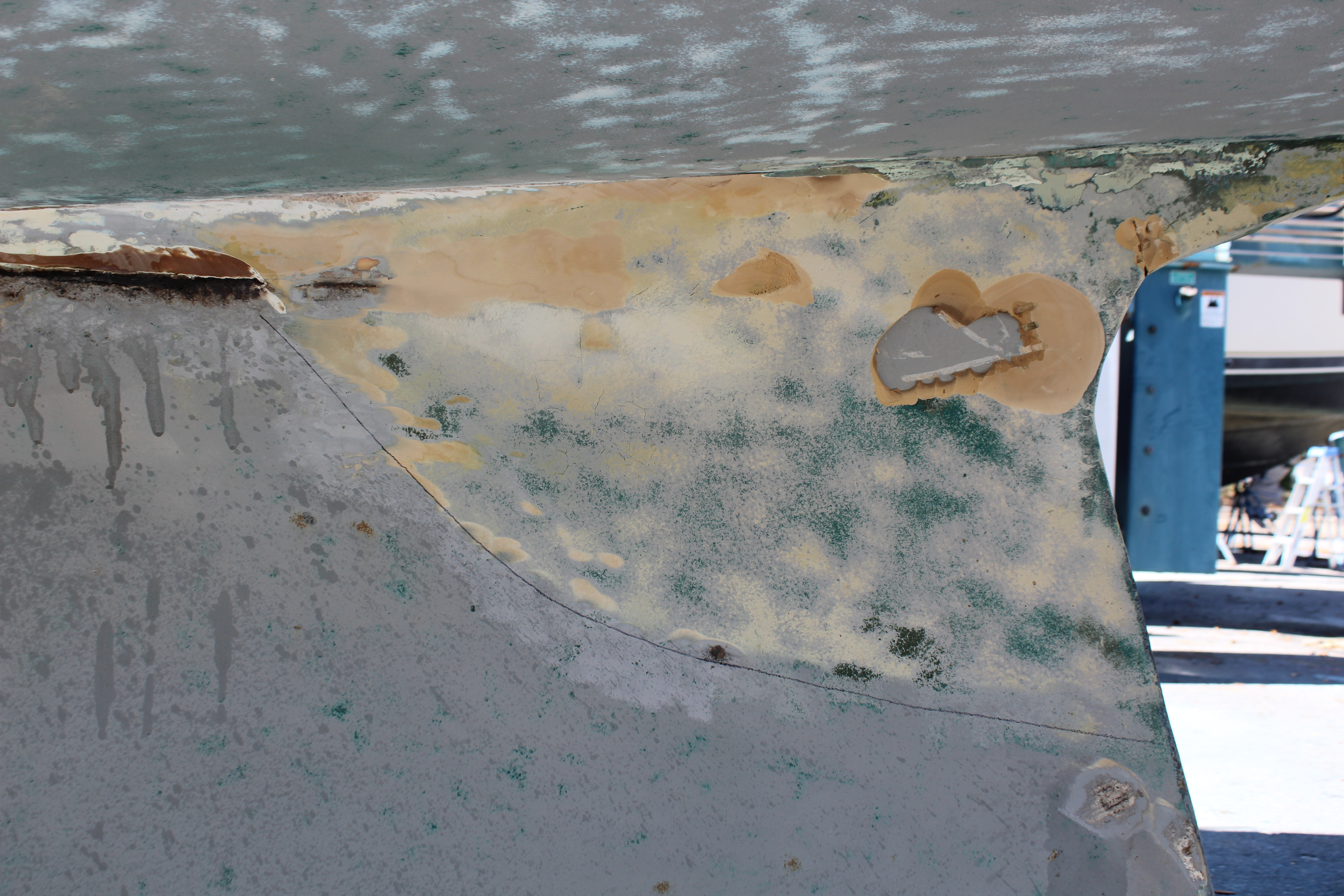
A I kept grinding away at to expose the keel joint I reached a point about three feet in front of the rear of the keel where the joint was covered in fairing compound (or whatever they used as fairing compound). Kept grinding and it kept getting thicker so I took a step back and did some thinking as to what was going on. While I was staring at the keel it became apparent that this was a rather large area covered with fairing compound (Hmmmm!) and quite a few spots that - after a hit with the grinder - looked like this:
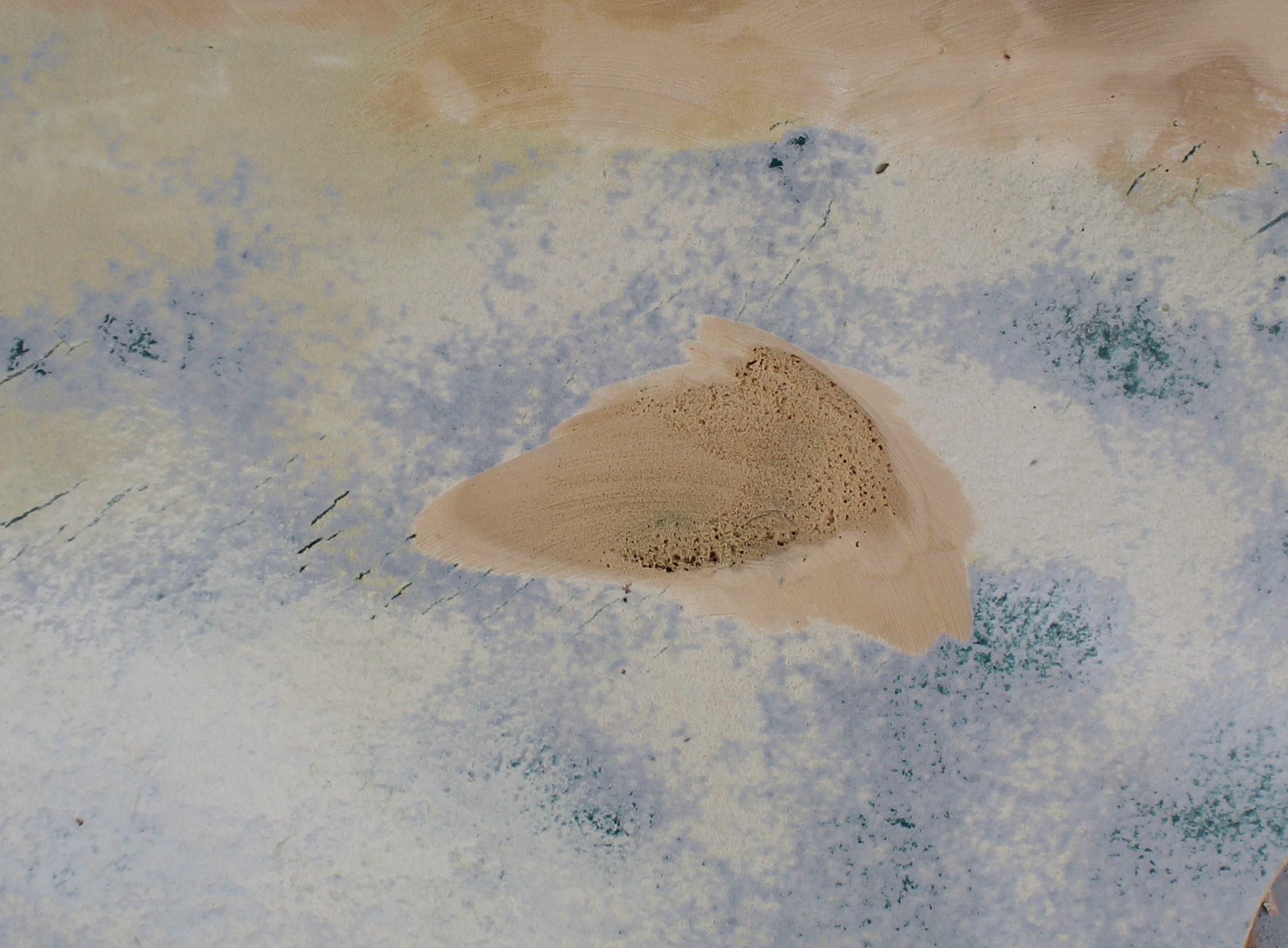
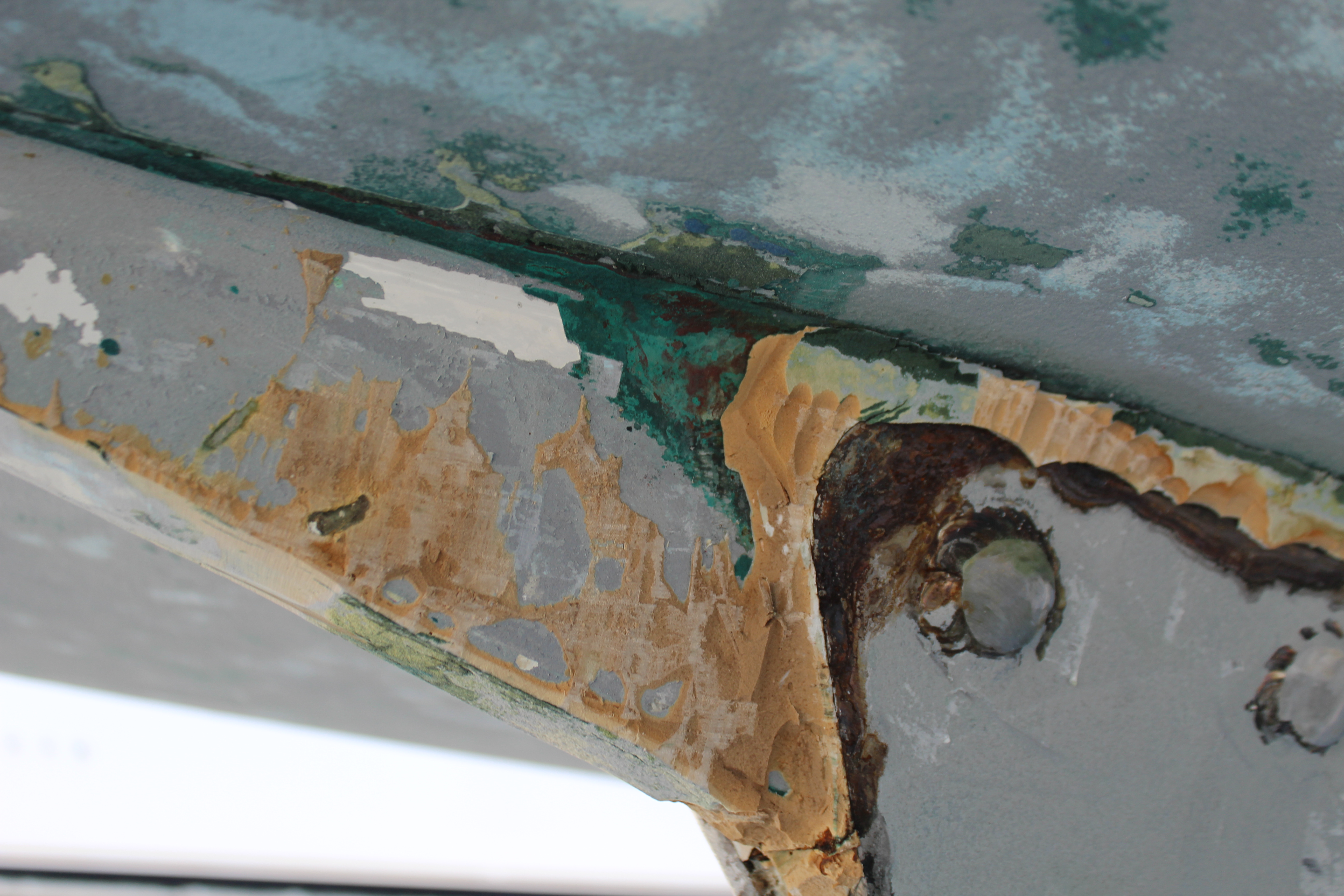
This was visible through the remaining primer and areas like this were spongy to the touch. Obviously applied badly. I kept grinding away at the filler and - finally - got to the keel! All around this spot the filler was not well adhered and I could chip it off easily with a screwdriver. Double Hmmmm. The filler was really thick and most areas showed cracking that usually is indicative of a too-thick application of filler that has shrunk. I kept chipping away and here's a progress shot:
It chipped off really easily - too easily . I worked on it until I hit metal - only it was metal in an area I was not expecting! Triple Hmmmmm! Ok, gotta see what's under all this! Here's a shot of the filled area on the other side:
Total area just under 3 feet by 2 feet. Intrigued, mystified, a little horrified, I kept chipping away. Finally I got to this:
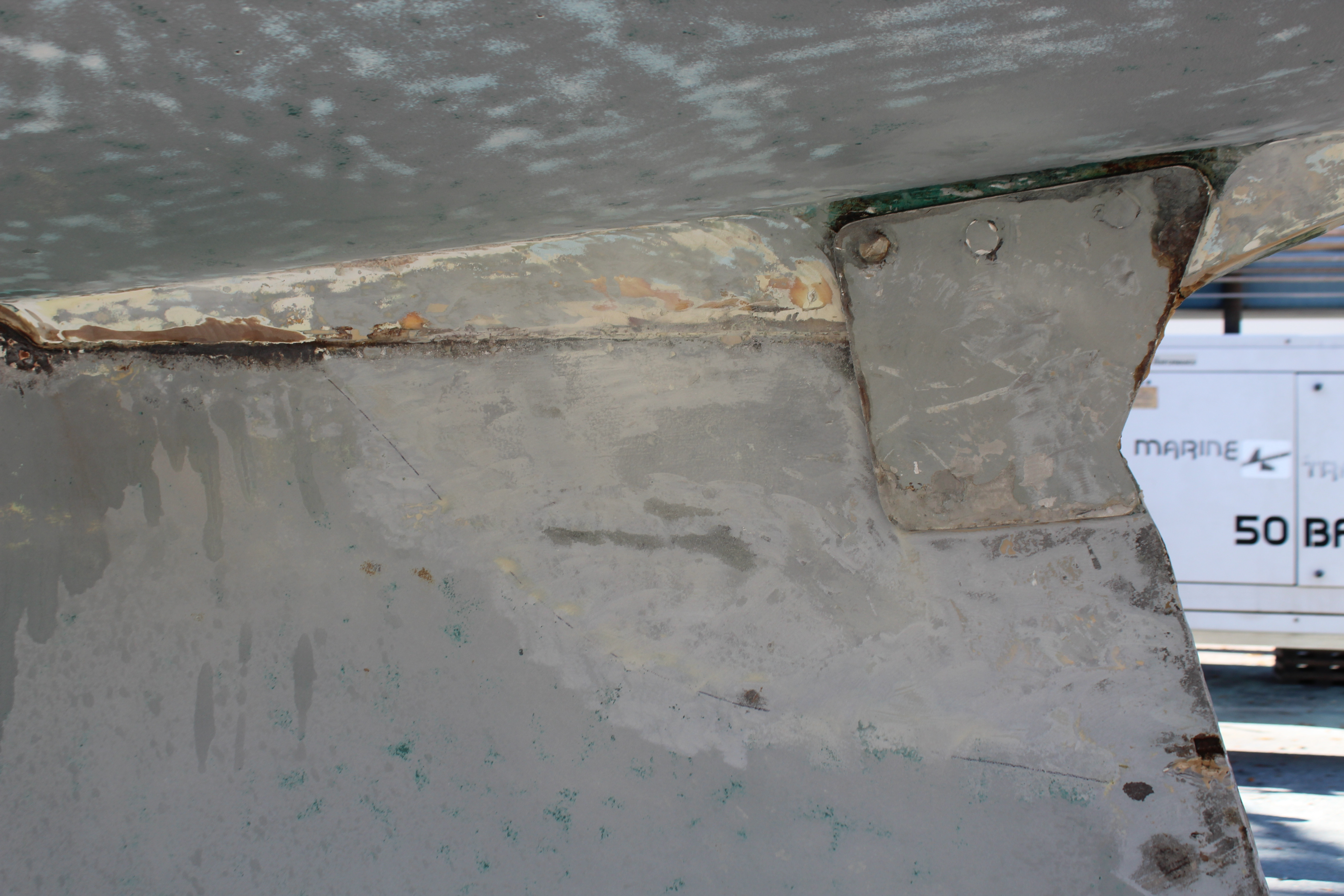
This is a 1/2" thick shaped plate (both sides) thru-bolted through the stub and welded to each other and the rear of the keel! What the he** is this? I know it didn't come from the factory this way - that's obvious when you see this:
That's an area that was covered with filler that had been applied over bottom paint! Which explains the rust under the filler. The total area of filler was needed to fully cover the thickness of the plate, and in areas the filler was close to if not over an inch thick. So...
a: I can't un-chip the removed filler so - gotta repair it
b: I would not tolerate this type of sloppy work on my boat so it will be fixed correctly!
c: I already have a plan!
What me and the guys here can't figure out is what this repair was for! There's no evidence of hull damage due to a grounding (believe me, we looked inside and out, and based on the quality of the filler job any underlying repair would have been noticeable). The keel itself is solid - and the bolts were at proper torque specs. There's no other repair areas on the keel. There's no apparent keel damage unless it's under the plates - and I can see the rear of the keel between the plates from behind. It looked like the plates were formed, shaped and installed very well which leads me to think that whatever happened a naval engineer might have been consulted. As usual it was the final steps in the repair that turned to.
The silver lining? Based on what I'm looking at, the repair makes the keel stronger than factory. I'm less worried about running over a submarine now!
Stay tuned for the repair plan.
Cheers,
Mark
A I kept grinding away at to expose the keel joint I reached a point about three feet in front of the rear of the keel where the joint was covered in fairing compound (or whatever they used as fairing compound
). Kept grinding and it kept getting thicker so I took a step back and did some thinking as to what was going on. While I was staring at the keel it became apparent that this was a rather large area covered with fairing compound (Hmmmm!) and quite a few spots that - after a hit with the grinder - looked like this:
This was visible through the remaining primer and areas like this were spongy to the touch. Obviously applied badly. I kept grinding away at the filler and - finally - got to the keel! All around this spot the filler was not well adhered and I could chip it off easily with a screwdriver. Double Hmmmm. The filler was really thick and most areas showed cracking that usually is indicative of a too-thick application of filler that has shrunk. I kept chipping away and here's a progress shot:
It chipped off really easily - too easily
. I worked on it until I hit metal - only it was metal in an area I was not expecting! Triple Hmmmmm! Ok, gotta see what's under all this! Here's a shot of the filled area on the other side:
Total area just under 3 feet by 2 feet. Intrigued, mystified, a little horrified, I kept chipping away. Finally I got to this:
This is a 1/2" thick shaped plate (both sides) thru-bolted through the stub and welded to each other and the rear of the keel! What the he** is this? I know it didn't come from the factory this way - that's obvious when you see this:
That's an area that was covered with filler that had been applied over bottom paint! Which explains the rust under the filler
. The total area of filler was needed to fully cover the thickness of the plate, and in areas the filler was close to if not over an inch thick. So...a: I can't un-chip the removed filler so - gotta repair it
b: I would not tolerate this type of sloppy work on my boat so it will be fixed correctly!
c: I already have a plan!
What me and the guys here can't figure out is what this repair was for! There's no evidence of hull damage due to a grounding (believe me, we looked inside and out, and based on the quality of the filler job any underlying repair would have been noticeable). The keel itself is solid - and the bolts were at proper torque specs. There's no other repair areas on the keel. There's no apparent keel damage unless it's under the plates - and I can see the rear of the keel between the plates from behind. It looked like the plates were formed, shaped and installed very well which leads me to think that whatever happened a naval engineer might have been consulted. As usual it was the final steps in the repair that turned to
.The silver lining? Based on what I'm looking at, the repair makes the keel stronger than factory. I'm less worried about running over a submarine now!
Stay tuned for the repair plan.
Cheers,
Mark
I was gonna request that you guys save post #757 for me, but . . .
757!

I'm actually flying it in this shot!
and from the UAE:

Me pulling in from an all-nighter.
Cheers,
Mark
757!
I'm actually flying it in this shot!
and from the UAE:
Me pulling in from an all-nighter.
Cheers,
Mark
Perhaps a stab in a very dark place, but the plates were added to the keel to assist in relocating it. The plates were added the bolts were loosened and the keel was separated from the stub for resealing the plates acted as guides to help support the keel while the Keel to hull joint was being cleaned and new sealant applied. Just my guess.
Our theories so far are, like you said, fixing a damaged keel bolt, but the rear keel bolt is about 3 feet forward of this and torqued to spec (I actually cleaned this one up, rebed the plate and re-torqued the nut). There may have been another keel bolt farther aft but I can't see any evidence of one or any place for one. There might have been a casting flaw - a crack, a void or something like that - in the very rear portion of the keel that showed up soon after launching. The repair to me has, not an actual factory repair, but a factory authorized repair feel to it, so the plates are covering something on the keel that filler could not.That should be posted on the weirdest things found on a boat thread. The only thing I can think that may be fixing is a damaged keel bolt. It sure looks beefy.
Our theories so far are, like you said, fixing a damaged keel bolt, but the rear keel bolt is about 3 feet forward of this and torqued to spec (I actually cleaned this one up, rebed the plate and re-torqued the nut). There may have been another keel bolt farther aft but I can't see any evidence of one or any place for one. There might have been a casting flaw - a crack, a void or something like that - in the very rear portion of the keel that showed up soon after launching. The repair to me has, not an actual factory repair, but a factory authorized repair feel to it, so the plates are covering something on the keel that filler could not.
Any chance that someone at Hunter would know? might be worth reaching out to them.