Pimp my C275

Jun 6, 2016
204
Catalina 275 Wilmette, IL
Seeing that the moderators were gracious enough to create our own C275 group, I figured we need to take advantage of that. Anyway, I've done probably nearly a dozen mods to my C275 (some small, some bigger) and wanted to create a thread that all C275 owners could post their mods for others to consider. I'll start out with a one of my early mods, but the picture actually shows two, but I'll only discuss the one I intended.

I purchased new and took this as an opportunity to exclude items that I was not interested in. In this picture, I replaced the stock panel with a self-installed Blue Sea 8402, which importantly gives me 10 individual breakers, battery voltage as well as amp usage.

P1020369.JPG


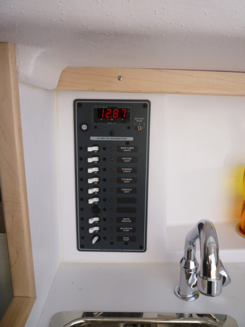
Since then, I've connected a foredeck light, 2nd battery and stereo (all future posts). I broke away from tradition and filed the bilge pump tab to be auto to the left and manual to the right. This way if someone, ie. my wife, flips all the switches to left, the bilge remains on. Really hasn't ever turned on anyway, but just in case.
 
Jun 6, 2016
204
Catalina 275 Wilmette, IL
My next mod was done with the intent of installing a second battery so I had Catalina not install the front mounted (correction: back mounted on front mounted cover) battery switch and I installed two back mounted Blue Sea 9001e. It would take a year for me to install the second battery because it took a year for catalinadirect to get the battery tray I wanted, but that will be a different post. I also had Catalina provide 1/2" wood backing, which ended up being glassed in (not on request) and the backing was not uniform in thickness. It took a bit of work to get the switches to sit properly, so in hindsight I should have just glued the backing on myself and had more control over the backing thickness. Anyway, after quite a bit of fussing around, this is what I ended up with:

P1020370.JPG


The left side common is connected to the electrical panel and the right side common is connected to the starter/alternator allowing either to select which battery to get its power from. Obviously, I only had battery 1 to choose from for the first year. The batteries (house & starter) are connected to 1 & 2, respectively, on the right selector with 4 ga. jumpers to the left selector. I do not have a clean picture of the back of the selectors, so this will have to do:

P1020713.JPG


As you can see for the starter selector, it gets a little tight there, but it can be done. If you are wondering, the blue line is a temporary keep-in-place wire puller that I have replaced with scrap 14 ga. wire.
 
Last edited:
Jun 6, 2016
204
Catalina 275 Wilmette, IL
The next mod is really three interconnected mods which I will post separately and since I'm missing some pictures, it may be a bit before all three are posted. I had Catalina keep their toilet so I could install an upgrade ceramic toilet. I went with the Raritan Marine Elegance toilet, specifically, model 220HF012 white, standard, angle back, w/ smart flush control. The big oops by Catalina was they decided I would want seawater supply, because its "free", and went ahead and drilled through the side of the head for it. I was quite depressed driving away with my new boat, especially after I had stated in my instructions, "NOTE: Customer installed toilet will use fresh water supply, so sea water connect is not needed." Being on Lake Michigan, fresh water is basically a disposable commodity. I tried to fix it up the best I could with a Catalina provided cover that I cut down to 1/4" thick but I'm still a little bummed. That's just my OCD kicking in. Anyway here is the installed toilet:

P1020371.JPG


The electric flush control, which is a big hit with the women:

P1020373.JPG


And the back of the toilet showing the 1/2" water supply, electrical wires and 1" Raritan Sani/Flex hose, which is extremely flexible and so easy to work with:

P1020374.JPG


Very happy with this mod. Future related posts will be the holding tank and pressured water.
 
Jun 6, 2016
204
Catalina 275 Wilmette, IL
what - no bidet ??
You know, that one slipped my mind. I suppose a future handheld off the back could substitute, but I wonder if Toto makes a 12V Washlet, which would certainly be more civilized.
 
Jun 6, 2016
204
Catalina 275 Wilmette, IL
This is part 2 of my 3 part toilet mod. I had several concerns about the stock holding tank. Since I was installing my own toilet, I thought I would take the opportunity to upgrade the holding tank as well. My two biggest concerns with the stock holding tank is that a good starboard tack heal could cause backflowing through a leaky toilet pump seal and the single ventilation through a 3/4" hose would be more prone to smell (search "MARINE SANITATION : Fact vs. Folklore" by Peggie Hall). So I had a custom tank built by Ronco based on their B265 tank. This is the drawing I provided to Ronco:
Ronco_B265.jpg

(Ronco_B265.pdf). It has two 1" vents; the inlet is on the top (center line); the outlet is moved aft to make room for the fresh water pump; 14 gallons instead of standard 12; and, added a 1-1/2" port in case I wanted to add a type I MSD. I also used a picture from hull #5 to modify the location of a hose loop:

Hose & Coolant.jpg


I ended up rotating the tank so it is really 14 1/2" high and I did end up moving the coolant tank forward because Catalina located it a lot more aft than pictured. The hose loop was my biggest concern and that worked out. This is the installed tank:

P1020416.JPG


I didn't specify a color and it came white. Positive, I can see the level. Negative, I'll probably have to clean the inside at some point; whereas, black is out of sight, out of mind. I also added wood blocking, on both sides, to prevent movement while healing. It is on a bigger platform (23 1/2" fore/aft) than stock because I may, but doubtful, install a type I MSD. Also, at the top, you can see the toilet controls that goes with the previous post. I replaced the brass fitting for the stern vent to accommodate the one inch vent hose. Not wanting to drill a second vent hole through the boat, I T'd into the manual bilge line:

P1020419.JPG


Not ideal, but good enough for me, and yes, before you make any comments, I should double clamp the T.
 

Attachments

Jun 6, 2016
204
Catalina 275 Wilmette, IL
It's been a bit of a delay. but the third part of the previous mods is adding pressured water to the C275. Considering I needed a water pump for the toilet, I figured I might as well add pressured water for the sinks. I had Catalina keep the hand pumps for the two sinks and added Scandvik #10169 for the galley sink and Scandvik #10050 for head sink (both use adapter Scandvik #10026 to connect to 1/2" hose). These are the pictures for the faucets:

P1030230.JPG


P1030231.JPG


I went with the Jabsco Sensor Max 14 variable speed pump, which has been discontinued in favor of the VFLO. Considering the unfavorable reviews of the VFLO at WM, I'll probably consider a different brand when the pump eventually fails (it's a boat). I mounted the pump in the stern locker for accessibility:

P1030234.JPG


With the water tank being on the opposite side of the head, I was able to snake two 1/2" water hoses under the head floor to connect the pump to the water tank and the sinks. I originally tried a 3/4" hose from the tank to the pump but had too much trouble getting it to go under. Maybe a 5/8" would fit, but I didn't consider that.

So this completes the plumbing mods. Considering the C275 is rather bare bones down below, I thought I would add a few items that while not necessary, just make it a little nicer.
 
Jun 6, 2016
204
Catalina 275 Wilmette, IL
Another addition to my C275 is a deck light. As there is already wiring from the panel to the base of the mast, I figured I'd add a deck light which I have found to be handy when pulling into my unlit slip. I added the Marinebeam LED Combination Masthead/Deck Light (picture of the mast on a rack):

P1030242.JPG


I used a heat gun to help bend the mounting flaps. Found round three wire on ebay and spent an hour in the rain with my wife trying to pull it up the mast getting hung up on the multiple styrofoam inserts. In hindsight, instead of using a pulling line, it may have be better to connect the new wire to the old so that it would follow past the inserts and not catch as easily. Possibly using crimp connectors to two of the wires and tape it so it is all smooth. Just make sure it can bend coming out/going in the hole in the mast. Attach a runner line to the old wire as a safety in case the wires disconnect.

In order to make room for the wires coming out of the mast, I cut some of the ribs on the back of the light which are not structurally significant. The Marinebeam is not an inexpensive light, but I'm happy with the results.
 
Jun 6, 2016
204
Catalina 275 Wilmette, IL
In light of the fact the Medallion manufactured tach can support water temperature in the LCD display, I decided to install a water temp sender on the 2YM15 engine. After experimenting with some resistors, I concluded the panel is programmed for a VDO sender, which I was able to confirm with Medallion. The one caveat is Medallion has a bug in their firmware and the temperature reads low as well as being slow to respond (20 seconds). The lag may be intentional. The oil pressure display does not lag and appears to closely match VDO specs. I have not had success with Medallion to fix the temperature problem but I am pursuing this with Yanmar America. Hopefully something happens but being the only person requesting this fix, I'll probably be ignored. If nothing happens in two years, I'll consider reverse engineering it. If that happens, I'll add a fuel gauge display to the LCD because I used the fuel gauge hole for something else (future post). The wires for water temp, oil pressure and fuel are all there in the tach's wiring harness. If you look at the tach wiring harness on the back of the tach you will find an unused female connector with three male pins and looks like:

P1030005.JPG


For the water temperature, all you need to do is hook up a single wire between the white wire and the temp sender you will install on the engine. The connector is made by Amphenol SINE Systems. You'll need part numbers (quantity): (1) AT06-08SA (male socket), (1) AW8S (wedge), (7) A114017 (blank seal), (1) AT62-201-16141 (female pin for 16-20 AWG wire) or (1) AT62-209-16141 (female pin for 14 AWG wire). I would buy extra female pins if you ever want to connect to the other two wires or if you just mess up. These parts are available at mouser.com and digikey.com. I used 18 AWG wire for my connection. The installed connected plug looks like:

P1030263.JPG


The sender is easy to install. Just need to unscrew a plug and screw in the sender into the top front of the engine. The European part number is 323-801-001-029 (120C M16x1.5). The American part number is 323-417 (250F M16x1.5) which I got from jegs.com. Installed, it looks like:

P1030266.JPG


I thought about hooking up an oil pressure sender (10 bar VDO), but the 2YM15 is extremely tight by the oil switch. I highly doubt I could fit a T and the sender in the space. I'm not even sure if there is enough room to replace the switch with a combo sender/switch. Further, while I believe the thread in the engine is 1/8 BSPT, it could be 1/8 – 27 NPTF or a different size altogether. I wouldn't know until I removed it and inspected the threads. It would be nice to install but I haven't convinced myself to go through the trouble for something that I may or may not be able to fit. Picture of the oil switch follows as well as the graphs I made matching the tach to the senders.

P1030036.JPG WaterTempChart.jpg OilPressureChart.jpg
 
Jun 6, 2016
204
Catalina 275 Wilmette, IL
I never thought I would get excited about a latch, but that happened today. I really should say two latches. Unless you've used the cooler on a C275, it is really not possible to understand my excitement. The locking system for the cooler drawer is one of the most Mickey Mouse'd items I've seen a manufacturer do on a sailboat. Especially, an $80k sailboat. Catalina drilled a hole in one side of the cabinet and you're suppose to slide a 1/4" pin from the adjacent cabinet to lock the cooler from sliding open as you sail. If the cooler is full, it does nothing to prevent the other end from trying to torque out a bit while on starboard tack.

After three years, I had enough and looked for a solution. Found two Southco M1-63-8 latches on ebay for $58 (including shipping) and another $4 for screws: (4) 5mm x 14mm, (2) #12 x 1/2", (2) #12 x 1". Drilled (2) two inch holes in the front of the cabinet, carefully drilled holes for the keeper, clipped the tips of the #12 screws so they don't come through the side of the cabinets and added a spacer on the right side. Now I have a cooler drawer that works like you would expect a drawer to work on a sailboat. This is a mod that was well worth it and is exactly what Catalina should have done in the first place. I have a 32 nm first sail of the year in two weeks and I expect to be on starboard the whole way, so that should be a good test for the 187 lb rated latches.

P1030292.JPG
 
Jun 6, 2016
204
Catalina 275 Wilmette, IL
My wife got to try out the cooler drawer latches yesterday and agrees it is sooooooo much better than the stupid pin.

This next modification is a simple mod. I bought all the gear for the 106% jib but less the jib. I thought it would be nice to use the 106 jib lead cars to stop the self-tacker from banging from side to side on a deep downwind. Unfortunately to get the jib lead car on, the plastic piece at the end of the track needs to be removed. That's fine if the jib lead cars are going to be permanently on the track, but I rather only have them on when needed. My solution was to mount one of the plastic end piece (from each side) on a piece of wood and shave the underside with the table saw (see thumbnail for work in progress). Had to take enough off where I completely removed the two tabs that align into the rail in order to work as the mounted rails are not the same exact height. I also, did multiple passes instead of two per side to prevent the plastic from shattering. I don't think it will shatter, but why take the chance.
P1030405.JPG
 
Jun 6, 2016
204
Catalina 275 Wilmette, IL
With the toilet connected to the fresh water, I thought it would be nice to be able to determine the water tank level. On my boat, the water tank is under the saloon seat and is not readily accessible to view the level. I installed a tank gauge from ferriellosales.com under the seat in conjunction with a 4 pin Amphenol (see above) disconnect so the tank cover can be removed. Another 2 pin disconnect could come in handy if removing the water tank. This is a picture of the gauge installed into the tank cover:

P1030291.JPG


Could have saved $5 and gone without the "Tank Empty" light, but I didn't know where I was going to install it at the time I bought it. Since I don't use a lot of water and only need to check it occasionally, I decided I'd rather cut into replaceable wood instead of fiberglass. Upon filling, tank changes from empty to quarter full somewhere between 4 and 4.5 gallons on the 15 gallon tank.
 
Jun 6, 2016
204
Catalina 275 Wilmette, IL
Having installed a second battery (future post) and the bluetooth speaker in the cup holder was not quite cutting it, I finally installed a fixed mounted stereo. But I dreaded the thought of cutting holes in the cockpit for speakers that never survive the abuse of weather and being kicked. Additionally, there really is no ideal place to mount speakers on the C275. Happen to stumble across a thread on cruisersforum.com that suggests using exciters instead of speakers. At $20 apiece, I had nothing to lose and I can always cut holes in the future. This is a mounted exciter:

P1030296.JPG


It's not high fidelity and the only way you'll rock the sandbar is with your keel, but I'm very happy with the results. Great way to add music to the cockpit. It's also fun when you notice the occasional guest trying to figure out where the music is coming from. Fiberglass is a little bassy so you'll probably want to experiment with the stereo settings. Another thing, placement is very important and one person should be holding the speaker to the glass and another topside giving feedback. Centered and away from doubled up glass seems to be the best.

I went with four TEAX32C20-8 exciters from parts-express.com. With the non-CD Sony DSX-M50BT rated at 55 watts at 4 ohms, I used two 8-ohm exciters in parallel becoming 4 ohms. And instead of left-right, I did center-aft, ie. left-rear speakers are under crew seat at calf height and the right-rear are behind the helmsman backrest. I sanded the textured surface smooth before mounting to the glass. The inner ring of the TEAXs adheres to the glass. Unfortunately, it does not hold up in a closed up, hot boat. So if you install these speakers, rub off the glue and use contact cement. I made a pattern so I could mark three rings, two for the glue and one on the outside for alignment. As an alternative to holding the speaker wires up with screws (foam tape hangers from HD would not stick), I used a hot melt glue gun. The glue allows securing the entire wire length and is holding up a year later.

I was happy enough with the speaker results, this spring I added four more speakers under the saloon seats, where right-front is fore and left-front is aft. Thus, instead of the typical left-right, I have centered-ends, respectively, with the eight speakers in case volume adjustment is ever needed. Under the saloon seat is painted, so the paint needs to be removed first (and let the stripper dry) because the contact cement melts the paint. Also, since I only use about 5 gallons of diesel a year, I relocated and zip-tied the fuel gauge underneath the cockpit locker so I could control volume while sailing without drilling a new hole (obviously, I have something against drilling holes). Here are thumbnails of the installed radio and remote.

P1030431.JPGP1030239.JPG
 
Jun 6, 2016
204
Catalina 275 Wilmette, IL
As I mentioned in "Problems", the Hella Marine bow light cover disappeared. It appears from a crack in the plastic base, there was a sideways force. Maybe the spinnaker sheet (?), but I thought I would have notice the light missing as I jumped from the dock to the bow at least twice since using the spin. Anyway, instead of replacing with same, which is likely to fall off again, I upgraded to Marinebeam N1-112-RGN (led) and at the same time bought a replacement 30 led festoon bulb for the stern light, which knocked me up to free shipping. The new bow light is rounder and projects less so hopefully this doesn't happen again. It is also rated for 2 nm visibility instead of 1. Here is a picture installed:

P1030445.JPG


It is certainly bigger than the Hella and the mounting plate, but it's not too bad only projecting about 1/8 to 3/16" below the support. This is the back:

P1030446.JPG

Tapped 8-32 threads into the plate using the tap I bought for my next modification post. The 8' wire lead is enough to get into the boat by about 2' and was easy to splice into the old wire having to only remove a pvc cover with two screws. With the new bow and stern LED lights, the running lights dropped from 1.4 amps to 0.3 amps on the panel. Unfortunately, the same Marinebeam light for the stern is too big, so when I lose the Hella stern light for a second time, I'll replace with the Marinebeam economy Aqua Signal 25 replacement and move the stern replacement LED up to the anchor light.
 
Jun 6, 2016
204
Catalina 275 Wilmette, IL
Sailing the boat for the first time, I was not impressed by Catalina's configuration of the outhaul cam cleat. It could be tightened from the cockpit, but to loosen, you have to climb on top of the cabin. Mounted a Selden BBB40 block at the base of the mast and removed the teeth of the cam cleat on the boom so I could operate both directions from the cockpit. Unfortunately, I could not find a good angle with the adjustable cam cleat that allowed both easy cleating and releasing so my fix was not much better. Happen to come across the Spinlock PXR0206 which is really small and could squeeze in next to the line clutches.

P1030424.JPG


Did the same for the cunningham. I raised the cleat 1/4" to prevent the outhaul from rubbing on the top of the cabin. I used foam PVC (HD #206402741) which cuts and sands quite easily. Embedded in the glass under the clutches is a 3/8" thick aluminum plate. I used a 8-32 tap and corresponding drill to create the holes. I used a new tap, cutting oil and backed out when it started to bind to remove the aluminum chips. Takes a few attempts, but I didn't want to damage the aluminum threads or worse yet, break the tap. I originally used 8-32 x 1.5" flat head countersunk screws but I cracked the front mount on one of the PXRs. Ted with Spinlock USA volunteered to replace it at no cost which was really nice of him. I believe it cracked because either the foam PVC or because the 8-32 screw is a 82 degree countersunk and the PXR is made for the metric 90 degree countersunk. I suspect the latter is the most likely cause. If I was manufacturing the PXR, I would get rid of the countersunk which would add additional strength as well as eliminating the 82 degree issue. Anyway, I replaced with 8-32 x 1.5" pan head screws with two fingers and thumb tightening and all is ok.

The cleats on the Selden BBB40 and the existing cunningham can be removed so I didn't have to buy new blocks to go with the PXRs. I also removed the remaining cleat assembly on the boom and replaced with two layers of foam PVC using 4 x 0.7 x 20mm pan head screws. See thumbnails.

P1030420.JPGP1030419.JPG

I'm using the foam PVC here to reduce the friction on the outhaul going into the boom. Additionally, I use this for a place to hook my self-designed minimalist lazy jacks (no mounted hardware or cover modifications (future post)).

The PXR0206s are working really well for the outhaul and the cunningham and I'm very happy with the install. I had to add a couple of drops of Harken One Drop to one of the cams for smoother operation. I use the One Drop for the main traveler and jib track bearings.
 
Jun 6, 2016
204
Catalina 275 Wilmette, IL
This is a simple mod for a annoying problem with the main traveler. During a jibe, there is a tendency for the traveler line to catch the top side of the blocks limiting the traveler. I originally used a line to fix the problem:

P1030449.JPG


But swapped it over to two separate 7" zip-ties per side:

P1030451.JPG


which is a little more discrete.
 
Sep 8, 2014
2,551
Catalina 22 Swing Keel San Diego
Loving this thread... I appreciate you ingenuity in chosen modifications and the attention to fit & finish when you implement. Nothing drives me crazier than 'hack' mods and shoddy work quality on brand new sailboats... nothing you have to worry about on this vessel!
 
Jun 6, 2016
204
Catalina 275 Wilmette, IL
Thanks for the compliments. Looks like I'll need to add to this thread so it doesn't become stagnate. I went and took pictures yesterday to document a modification, but I want to try something else before I document and it will be at least a week. In the mean time, I'm just going to throw in another simple mod to make life easier.

If you have ever been in the situation where you or your guests can't remember which engine button does what without trying to decipher the symbol, then I recommend using electrical tape that you can pickup at HD and similar:

P1030493.JPG


My red tape is about 20 years old so it fades and I have to replace twice a year, but the yellow and green are fade resistant and holding up quite well. Looks like I'll have to spring for a new roll of red for an inch of tape.

Also included in the picture is the engine temperature (engine cold) from my post #9 mod.
 
Sep 8, 2014
2,551
Catalina 22 Swing Keel San Diego
One of the things that drives me crazy is seeing engine controls topsides that are beaten up by the sun and weather to the point that they are oxidized, faded, and brittle... they look like crap and then fail to function. I just don't see why manufacturers haven't made a more concerted effort to place covers on them that have UV polarized & protective transparent plastic. I have seen just a few examples of this, some by OEMs but mostly modifications by owners. Covers are difficult in this fashion because they need to be transparent enough to see the gauges, have and opening method so you can still turn the engine key and press the control buttons, but also allow water to drain and not hold moisture in the enclosure. By and large I see many cruising boats mount gauges and controls inside the cabin, but this isn't convenient to monitor engine function while at the helm. Other options are digital controls that transmit via bluetooth or wifi to portable screens, but that is obviously cost prohibitive for some owners and particularly small boats.
What I'd love to see is an innovative small business that create a solution to mount a 'bubble' shield on a hinge over the engine controls. The plastic is heat formed to a certain shape, the company would have to create various sizes without using expensive dies or molds. Each customer order would have to made to an owner provided template, with some stock or generic sizes available, in about 15 min or less of work. If the price point is good they are considered disposable after 4 to 6 years of service life, because nothing is completely immune to UV.
We can all dream right?
 
May 20, 2016
3,014
Catalina 36 MK1 94 Everett, WA
I moved mine up from where you couldn't read them to having them virtually at the helm -- I can display RPM, Oil Pressure, Temp, Volts.... all on either my I70 or e7D. Best of all I get audio and visual alarms if something is outside the range I set. I just occasionally check the analog gauges to make sure my digital representation of them is correct. Noland Engineering RS11 - great gadget to put our old engine vitals onto NMEA 2K.

Les
 
  • Like
Likes: jviss