Looking for some feedback on my proposed wiring upgrade.
Current Setup:
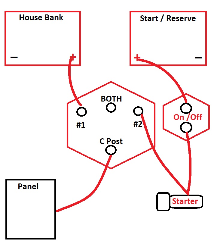
The boat came with 2 4D Wet Cells and I have already added a GRP 27 AGM as a Reserve and wired the 4D's in Parallel. The House Bank is wired to BATT Switch #2 and the Reserve to #1 on the 1/2/ALL. There is also an ON/OFF switch that is connected to the Starter and in turn tied to the "C" on the 1/2/Both. The Alternator is connected via the typical Jumper to the Starter at the engine and also has a separate 6AWG NEG going to the Engine main Ground (it is not Case Ground). In a previous thread, Maine Sail indicated that it would not be necessary to move that NEG to the Dist. Buss Bar that I am planning to implement. The Batteries are fused via MRBF's (300A at each Bank).
Proposed:
The attached Diagram reflects what I intend to add: An Echo Charger, Victron BM, and a pair of Distribution Buss Bars (POS and NEG) to get everything off the Battery Posts. Given my objective, I would appreciate any feedback on my proposed configuration. I am not entirely clear if the new POS Dist Buss Bar is the new 'Source' for the connection between the Buss Bar and Battery switch, but I assume it is, thus have added another fuse at that point. Also not sure if I want to add a mini ON/OFF at the Alt connection to the Buss Bar (no room in engine room near the Alt) for maintenance. Finally since MS has indicated that I can leave the NEG as is, do I need to increase Gauge on that wire? Wire length from Alt to Buss Bar will be approx. 13 FT, which equates to 26 RT IF the NEG ground were moved to the NEG Buss Bar. Currently the Neg from Alt to Engine Ground is about a foot. Thanks in advance...
Current Setup:
The boat came with 2 4D Wet Cells and I have already added a GRP 27 AGM as a Reserve and wired the 4D's in Parallel. The House Bank is wired to BATT Switch #2 and the Reserve to #1 on the 1/2/ALL. There is also an ON/OFF switch that is connected to the Starter and in turn tied to the "C" on the 1/2/Both. The Alternator is connected via the typical Jumper to the Starter at the engine and also has a separate 6AWG NEG going to the Engine main Ground (it is not Case Ground). In a previous thread, Maine Sail indicated that it would not be necessary to move that NEG to the Dist. Buss Bar that I am planning to implement. The Batteries are fused via MRBF's (300A at each Bank).
Proposed:
The attached Diagram reflects what I intend to add: An Echo Charger, Victron BM, and a pair of Distribution Buss Bars (POS and NEG) to get everything off the Battery Posts. Given my objective, I would appreciate any feedback on my proposed configuration. I am not entirely clear if the new POS Dist Buss Bar is the new 'Source' for the connection between the Buss Bar and Battery switch, but I assume it is, thus have added another fuse at that point. Also not sure if I want to add a mini ON/OFF at the Alt connection to the Buss Bar (no room in engine room near the Alt) for maintenance. Finally since MS has indicated that I can leave the NEG as is, do I need to increase Gauge on that wire? Wire length from Alt to Buss Bar will be approx. 13 FT, which equates to 26 RT IF the NEG ground were moved to the NEG Buss Bar. Currently the Neg from Alt to Engine Ground is about a foot. Thanks in advance...
Attachments
-
332.9 KB Views: 688
")