Another Wiring Diagram-Feedback Please

May 10, 2008
392
Catalina 355 Boston
Looking for some feedback on my proposed wiring upgrade.

Current Setup:
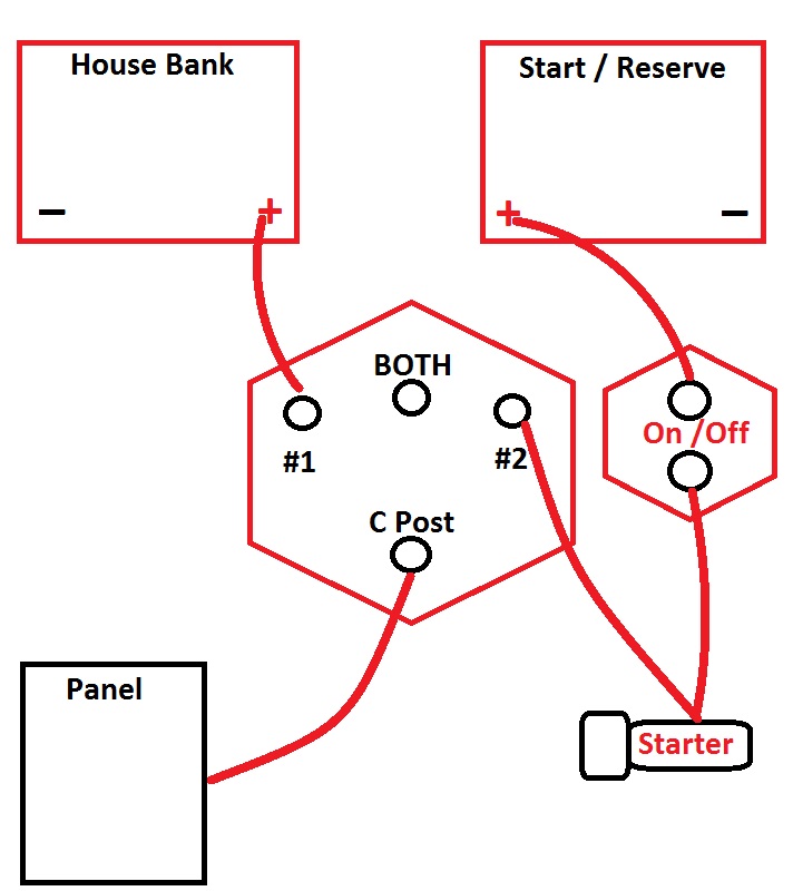
The boat came with 2 4D Wet Cells and I have already added a GRP 27 AGM as a Reserve and wired the 4D's in Parallel. The House Bank is wired to BATT Switch #2 and the Reserve to #1 on the 1/2/ALL. There is also an ON/OFF switch that is connected to the Starter and in turn tied to the "C" on the 1/2/Both. The Alternator is connected via the typical Jumper to the Starter at the engine and also has a separate 6AWG NEG going to the Engine main Ground (it is not Case Ground). In a previous thread, Maine Sail indicated that it would not be necessary to move that NEG to the Dist. Buss Bar that I am planning to implement. The Batteries are fused via MRBF's (300A at each Bank).

Proposed:
The attached Diagram reflects what I intend to add: An Echo Charger, Victron BM, and a pair of Distribution Buss Bars (POS and NEG) to get everything off the Battery Posts. Given my objective, I would appreciate any feedback on my proposed configuration. I am not entirely clear if the new POS Dist Buss Bar is the new 'Source' for the connection between the Buss Bar and Battery switch, but I assume it is, thus have added another fuse at that point. Also not sure if I want to add a mini ON/OFF at the Alt connection to the Buss Bar (no room in engine room near the Alt) for maintenance. Finally since MS has indicated that I can leave the NEG as is, do I need to increase Gauge on that wire? Wire length from Alt to Buss Bar will be approx. 13 FT, which equates to 26 RT IF the NEG ground were moved to the NEG Buss Bar. Currently the Neg from Alt to Engine Ground is about a foot. Thanks in advance...
 

Attachments

weinie

.
Sep 6, 2010
1,297
Jeanneau 349 port washington, ny
If you connect your alternator to your starter, rather than the pos. bus, you can use the existing on/off switch to disconnect power to your engine for maintenance/repair without losing house functions like your stereo.

This was my big gripe when I had to replace and oil pressure sender a few days ago. I had to remove the alternator and starter to get access. This involved turning my 1OFF2Both switch to OFF and thus losing power to my XM radio and cabin lights. Working in the dark without music wasn't much fun!

Just don't turn the switches while the engine is running or you'll blow your alternator.
 
May 10, 2008
392
Catalina 355 Boston
If you connect your alternator to your starter, rather than the pos. bus, you can use the existing on/off switch to disconnect power to your engine for maintenance/repair without losing house functions like your stereo.

This was my big gripe when I had to replace and oil pressure sender a few days ago. I had to remove the alternator and starter to get access. This involved turning my 1OFF2Both switch to OFF and thus losing power to my XM radio and cabin lights. Working in the dark without music wasn't much fun!

Just don't turn the switches while the engine is running or you'll blow your alternator.
This is how it is currently wired. Problem is the Alt needs to be directly connected to Batteries in order for Echo Charger to work properly. Trying to decide if adding a switch to Alt will introduce HEF. Frankly, if it weren't for the EC, I would probably leave Alt wired as is.
 
Feb 6, 1998
11,709
Canadian Sailcraft 36T Casco Bay, ME
This is how it is currently wired. Problem is the Alt needs to be directly connected to Batteries in order for Echo Charger to work properly. Trying to decide if adding a switch to Alt will introduce HEF. Frankly, if it weren't for the EC, I would probably leave Alt wired as is.
*No need for the second MRBF off the POS bus for the 2/0 wire it is already protected at the battery.

*No real need for the ON/OFF between the starter and "C" post that switch is already an ON/OFF

*Move ON/OFF to use as a service disconnect for alternator.
 
May 10, 2008
392
Catalina 355 Boston
*No need for the second MRBF off the POS bus for the 2/0 wire it is already protected at the battery.

Thanks. This was one of items I mentioned when putting together Purchase items for you.

*No real need for the ON/OFF between the starter and "C" post that switch is already an ON/OFF

Not sure I understand. That switch is integrated on a panel with the 1/2/ALL?. Are you suggesting rewiring this switch to Alt and moving Start wire to Common on 1/2/ALL?

*Move ON/OFF to use as a service disconnect for alternator.

Connect Alt to existing ON/OFF? See above.

Sorry...messed up the edit....
 
Last edited:

marian

.
May 21, 2010
47
beneteau beneteau 351 Penetanguishene
Dose ground cabe for reserve battery needs to be connected before shunt? I whant to install
a battery monitor on my boat. Maine Sail what will take to sent your Victron monitor to
Canada?
Marian
 
May 10, 2008
392
Catalina 355 Boston
Dose ground cabe for reserve battery needs to be connected before shunt? I whant to install
a battery monitor on my boat. Maine Sail what will take to sent your Victron monitor to
Canada?
Marian
Marian,

For a single battery monitor (Victron 600), every negative lead should be on the 'load' side of the shunt. The only connection to the House Battery should be a single lead from the House Bank to the 'BATT' side of the shunt. I don't see any value in monitoring a Reserve Battery...
 
Mar 16, 2009
2
2 36 Staten Island
My ideas

First off, I feel that the alternator + lead must be connected so it runs through the engine battery switch. As wired, you can never turn off all power to the engine since the + alternator lead will always be hot. Any work on the engine will be more dangerous.

Your choice of running the engine through 2 switches is odd and I am guessing it is so can charge all the batteries when the engine is running and also use all the batteries to start the engine.
I have chosen to use a battery combiner to solve the charging problem, it only allows current to flow when either battery is showing a voltage high enough to charge the battery. Hence when one battery is charging they all are charging. The BlueSea unit I have is rated at 120amps. It is not hard to install, two heave wires from the unit to each of the + on the two banks and a light ground wire so it can read battery voltage.
I guess, your reserve battery, is there to make sure you have a charged battery to start the engine, so why not keep it totally separate. I would move the reserve battery from the 1 2 all switch to the engine switch. Moving the jumper between the switches from the C terminal on the 12 All switch to the Batt 1 terminal would allow you to connect all batteries if necessary. The normal running position would be battery 2, reserve battery to engine, house batteries to house load. Switching to 1 would run everything off the reserve battery and All would use all the batteries.

The second charger; since you are already charging all batteries with the alternator I guess that you are not trying to charge with 2 different voltages. The battery combiner will allow the one charger you already have to charge all the batteries so the second charger is not needed.
 
Nov 18, 2010
2,441
Catalina 310 Hingham, MA
First off, I feel that the alternator + lead must be connected so it runs through the engine battery switch. As wired, you can never turn off all power to the engine since the + alternator lead will always be hot. Any work on the engine will be more dangerous.
You can do one of two things to remove power to the alternator with this setup. 1) As is, remove the 80 Amp fuse at the positive buss bar or 2) add an on/off switch between the alternator and the positive buss bar as a service disconnect. If you run the alternator as you suggest you still have the potential to blow the diodes by switching the 1/2/all/off switch.

Solstice, I've seen you out on the water. Good luck with your project.

Jesse
 
May 13, 2013
29
Tayana 48DS Phoenix, AZ
A couple of thoughts for you:

1. I would consider adding two isolators to your setup - one where you have the 2/0 between the two 4Ds, and one between your positive buss and the Group 27 "reserve" battery. This will do two things for you:
a) if a cell goes bad in one of your 4Ds, it won't take the entire pack down with it.
b) the Group 27 will be charged whenever your engine is running, even if you don't select it with the switch.

Here's what I'm talking about: http://www.defender.com/product.jsp?path=-1|328|51495|303336&id=1238033 - there are a number of different brands (and ratings) for these, this is one I found easily on Defender's website. These work by using a voltage-sensitive circuit to connect the batteries together when the voltage is high enough to indicate charging, and disconnect them when the voltage drops.

If you do this, you would want to bring a 2/0 (and a 300a fuse) from each battery to the #1and #2 terminals of your main "off/all/1/2" switch, and connect the "Common" of the switch to your house buss bar, so you could run your house on one or the other (or both).

2. You might want to consider making the Group 27 a "start battery" instead of a "reserve". Basically, connect it to the starter (via the fuses, etc.) alone, and use that big switch from it to the "common" of your house switch, in case you have to do a "jump" (as you have it drawn now). You wouldn't have any other loads on the start battery, so it should always be available to start the engine for you. This will mean that the starting current won't show up on your Victron, but I don't think that's particularly important. You would want to put in a way to monitor it's voltage, just so it doesn't go bad without you noticing..:)

It's a bit more wiring (and two somewhat expensive devices), but it's pretty bullet-proof, and doesn't require any active participation to work properly (something I like a lot, 'cuz I get distracted easily).

Hartley
S/V Atsa
 
May 10, 2008
392
Catalina 355 Boston
First off, I feel that the alternator + lead must be connected so it runs through the engine battery switch. As wired, you can never turn off all power to the engine since the + alternator lead will always be hot. Any work on the engine will be more dangerous.

Your choice of running the engine through 2 switches is odd and I am guessing it is so can charge all the batteries when the engine is running and also use all the batteries to start the engine.
I have chosen to use a battery combiner to solve the charging problem, it only allows current to flow when either battery is showing a voltage high enough to charge the battery. Hence when one battery is charging they all are charging. The BlueSea unit I have is rated at 120amps. It is not hard to install, two heave wires from the unit to each of the + on the two banks and a light ground wire so it can read battery voltage.
I guess, your reserve battery, is there to make sure you have a charged battery to start the engine, so why not keep it totally separate. I would move the reserve battery from the 1 2 all switch to the engine switch. Moving the jumper between the switches from the C terminal on the 12 All switch to the Batt 1 terminal would allow you to connect all batteries if necessary. The normal running position would be battery 2, reserve battery to engine, house batteries to house load. Switching to 1 would run everything off the reserve battery and All would use all the batteries.

The second charger; since you are already charging all batteries with the alternator I guess that you are not trying to charge with 2 different voltages. The battery combiner will allow the one charger you already have to charge all the batteries so the second charger is not needed.
Thanks for the feedback. However, just to clarify a few things. I agree with the ability to shut off power to Alt somehow for maintenance. I planned on either removing the fuse or adding a Blue Seas Mini ON/OFF at the buss bar which will be out of sight.

The reason the second switch is in the picture is because it came from the factory with a dedicated Switch panel this way (although not integrated in the Dist panel). As currently configured, that switch controls both the Starter and the Alt because the Alt is connected via the Starter Solenoid. I believe in an earlier response, Maine Sail is suggesting I move the Starter Cable to the the 1/2/All Switch and use the On/Off for the Alt. My only concern with this is that it creates the potential for someone to turn it off as it is in an open area. Right now that is not possible, since the starter will also fail to engage with that switch off.
When you say 'second charger', perhaps you are confusing the nomenclature of an Echo Charger? Its function is the same as a Combiner with a couple of differences. It is a one way device that basically trickle charges the Reserve from the House Bank at a max of 15A. Same simple 3 wire hookup as a Combiner. The advantage is that unlike a Combiner, it will not Combine a Large Bank and a Small Bank with the same charging voltage that is present; this is especially useful in my case as I have a large Wet Cell Bank and a small AGM bank--the AGM only gets charged via the House Bank when it needs it without any chance of undercharging the House while overcharging the Reserve. The gotcha is that all charging sources must be directly connected to the House Bank. I personally understand why Alts are direct wired, but I probably wouldn't bother if it weren't for the EC.
With both my current setup and the one I am moving to, I can use either battery, isolate either or combine all. I think you might be suggesting a dedicated Starting Battery setup? I know many people prefer a dedicated Starting Battery, but I prefer to use my House for everything, including starting....
 
May 10, 2008
392
Catalina 355 Boston
You can do one of two things to remove power to the alternator with this setup. 1) As is, remove the 80 Amp fuse at the positive buss bar or 2) add an on/off switch between the alternator and the positive buss bar as a service disconnect. If you run the alternator as you suggest you still have the potential to blow the diodes by switching the 1/2/all/off switch.

Solstice, I've seen you out on the water. Good luck with your project.

Jesse
Jesse,

I do plan to use either fuse removal, a mini switch or the existing on/off if I choose to move the starter to the 1/2/all switch. Not sure I follow how I can potentially blow the diodes with this setup though? Everything on the buss bar bypasses the switches except of course the switch connection itself--of course I could be missing something, which is why getting all the feedback is so helpful!

I will certainly look for you out there. I believe you are planning a trip to Maine this summer--done the trip dozens of times from our neighborhood, so if you would like any info, be happy to help!
 
Nov 18, 2010
2,441
Catalina 310 Hingham, MA
Jesse,

I do plan to use either fuse removal, a mini switch or the existing on/off if I choose to move the starter to the 1/2/all switch. Not sure I follow how I can potentially blow the diodes with this setup though? Everything on the buss bar bypasses the switches except of course the switch connection itself--of course I could be missing something, which is why getting all the feedback is so helpful!

I will certainly look for you out there. I believe you are planning a trip to Maine this summer--done the trip dozens of times from our neighborhood, so if you would like any info, be happy to help!
The blown diode remark was not aimed at your setup but the comment about tying the alternator in through the starter.

Thanks for the offer to help on the planning for our Maine trip.
 
Feb 26, 2004
23,047
Catalina 34 224 Maple Bay, BC, Canada
Solstice, It seems you are trying to use what you have and simply rearrange the wiring to make it "better." I agree.

You want to have the AO (alternator output) bypass ANY switches and run directly to the house bank, other than the on/off switch to isolate the electrical when you're working on the engine. That's a simple thing to do, as you've said, remove the fuse or add a small I/O switch. You got that part.

What you're trying to do is what Maine Sail and I have been "preaching" for the past 20 years. He's written it up and so have I. Try these, with links to his and my writeups. You're almost there.

The concept of having the AO go through the 1-2-B switch is, simply put, wrong. You want the echo charger to charge your reserve bank and not use the 1-2-B switch to be used as a charging determinator, but only source decider.

I'm almost sure you've already read these:

Basic Battery Wiring Diagrams This is a very good basic primer for boat system wiring: http://c34.org/bbs/index.php/topic,6604.0.html

This is another very good basic primer for boat system wiring: The 1-2-B Switch by Maine Sail (brings together a lot of what this subject is all about)
http://forums.catalina.sailboatowners.com/showthread.php?t=137615
 
Feb 6, 1998
11,709
Canadian Sailcraft 36T Casco Bay, ME
Solstice,

If that ON/OFF is already there you could always use it this way.


I incorrectly assumed you were adding it..


With the diagram above you retain all the isolation & redundancy of the 1/BOTH/2/OFF switch yet add a dedicated direct wired starting battery. Simply flip to #1 and ON and your ready to go. When you're done flip both switches to OFF. Label them carefully, Blue Sea sells the perfect labels...

*If the start battery were to fail flip the ON/OFF to OFF and the 1/BOTH/2/OFF to BOTH and now the house bank is starting and providing house loads.

*Conversely you can still use the start bank to power house loads in an emergency with the 1/BOTH/2/OFF in position #2 and the start switch to ON.

This system is more complicated but ultimately considerably more flexible than some other systems where you must use the "combine" feature in the event of a bank failure.
 
May 10, 2008
392
Catalina 355 Boston
Solstice, It seems you are trying to use what you have and simply rearrange the wiring to make it "better." I agree.

You want to have the AO (alternator output) bypass ANY switches and run directly to the house bank, other than the on/off switch to isolate the electrical when you're working on the engine. That's a simple thing to do, as you've said, remove the fuse or add a small I/O switch. You got that part.

What you're trying to do is what Maine Sail and I have been "preaching" for the past 20 years. He's written it up and so have I. Try these, with links to his and my writeups. You're almost there.

The concept of having the AO go through the 1-2-B switch is, simply put, wrong. You want the echo charger to charge your reserve bank and not use the 1-2-B switch to be used as a charging determinator, but only source decider.

I'm almost sure you've already read these:

Basic Battery Wiring Diagrams This is a very good basic primer for boat system wiring: http://c34.org/bbs/index.php/topic,6604.0.html

This is another very good basic primer for boat system wiring: The 1-2-B Switch by Maine Sail (brings together a lot of what this subject is all about)
http://forums.catalina.sailboatowners.com/showthread.php?t=137615
Stu,
You are correct, I am basically rearranging what I already have. By adding the EC and directing the AO to the House, the Bus Distribution becomes necessary. I have set this system up on previous boats (I have read these links over the years) and the intended setup is as described in many of those links. Perhaps my diagram needs work and the existing ON/OFF adds some confusion. My diagram is supposed to depict the following:
*All Charging Sources go to House
*House will be used for starting and house loads
*Reserve will be charged via the EC, NOT the 1/2/All
*The 1/2/All simply will allow me to choose which battery to use, or combine in an emergency (this should never be necessary as the Reserve should always be topped up) and not to select the charging source. The Switch will always be set to House, never need to change it under normal conditions;
*Hopefully my diagram does not depict the AO going through the 1/2/All as that is certainly not the intent.

This is actually how I am currently using the electrical system, but without the EC in place I have to occasionally top up the Reserve via the switch or the engine--this work is intended to automate this part.

As I mentioned, really appreciate the feedback, just trying to determine if my diagram is depicting (execution) what I am trying to accomplish...
 
May 10, 2008
392
Catalina 355 Boston
Solstice,

If that ON/OFF is already there you could always use it this way.


I incorrectly assumed you were adding it..


With the diagram above you retain all the isolation & redundancy of the 1/BOTH/2/OFF switch yet add a dedicated direct wired starting battery. Simply flip to #1 and ON and your ready to go. When you're done flip both switches to OFF. Label them carefully, Blue Sea sells the perfect labels...

*If the start battery were to fail flip the ON/OFF to OFF and the 1/BOTH/2/OFF to BOTH and now the house bank is starting and providing house loads.

*Conversely you can still use the start bank to power house loads in an emergency with the 1/BOTH/2/OFF in position #2 and the start switch to ON.

This system is more complicated but ultimately considerably more flexible than some other systems where you must use the "combine" feature in the event of a bank failure.
Thanks Maine Sail,
Yes that ON/OFF is already in place. I do prefer to use the House for both Starting and House loads as opposed to a dedicated Starting Battery. In my proposed setup I believe I will still be able to isolate the banks in the event my House fails as your diagram shows by selecting the Reserve. Since the EC is a 'one way' device it will not combine the bad bank with the good unless I select ALL. Question becomes how to best utilize that existing ON/OFF in this scenario.
Once the AO is off that Start circuit, it probably isn't a bad thing to be able to kill the Start solenoid for maintenance or if it sticks on etc., similar to creating a maintenance switch for the Alt?
Thanks very much for your feedback...
 
Feb 26, 2004
23,047
Catalina 34 224 Maple Bay, BC, Canada
*The 1/2/All simply will allow me to choose which battery to use, or combine in an emergency (this should never be necessary as the Reserve should always be topped up) and not to select the charging source.
Understood. Just never, never, never, never "combine in an emergency" 'cuz it is usually the worst thing you can do. Why? "Cuz one bank is down and out and it's the last thing you want to connect to.

If you read the links I provided, you'll find a discussion about the stupid Blue Seas DPC, which only combines bad banks when one is dead.

Your design goal, and the ones provided in those links, has this very, very important issue covered: your system should allow either bank to run your boat. Sure, if all you have is your reserve bank you can only run LIMITED house loads, but the diagram MS provided and I linked to will allow you to do that.

Sorry I haven't had the time to print out and mark up your diagram, but with this information you may be able to edit and repost it, so we may have another go at it.
 

PKFK

.
Jul 12, 2004
206
Hunter 36 Ottawa
Hi -

I have been reading Maine Sail's musings on battery switches, etc. and am going to install a Xantrex Echo charger on my H36.

I want to clarify something about the physical location of the echo charger.

The Xantrex manual says it comes with 2' connectors, and to locate the unit as close as possible to both the house bank and starting bank.

On my H36, the house bank (4 T-105's) is in the lazarette, while the starter battery is below the aft cabin berth, behind the engine.......these are clearly not within 2' of each other.

So the question is - what is more important for the echo charger to be closest to - the house bank, or the starting battery ?

And - what if I locate the Echo unit in the salon settee with the inverter and shore charger - which is about 10-12 cable-feet from both the house bank and the starting battery ?

The Xantrex Manual is not exactly the best document I have ever read thru ! :confused:

Thanks in advance for answering yet another (in a zillion) post about charging and switches !

Paul