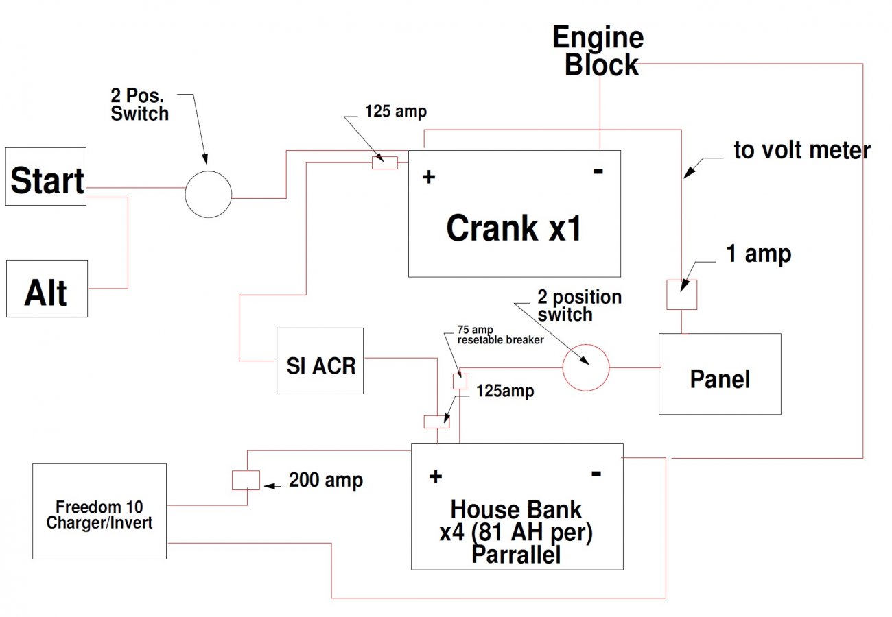
In preparation of installing solar to my boat, I have mapped out the main DC circuits to figure out where to install and evaluate any needs for change. I've been meaning to do this since its purchase last April and the project has motivated me to better learn the systems. Long story short I have a single crank battery and 4 house batteries in parallel. A Freedom 10 charger/inverter connected to the house bank. A Blue Seas SI ACR connecting the crank and house bank. The alternator hooked to the crank and the house bank feeding my Blue Seas panel which is two banks of 12 vlt breakers and a single bank of 120vlt, amp meter, 12 volt meter (with two bank positions) and a 120 volt meter. All positive battery posts have 125 amp fuses with the exception of the lead between the house bank and panel, it has a reset able 75 fuse.
I have drawn out the schematic below. From what I see and after researching the SI ACR, I need to move the alternator battery output off of the crank battery and to the house bank to it up a little. I am interested in additional input.
As for the solar circuit.....I'm thinking of adding it to the battery side of the 200 amp fuse for the charger. Thoughts?
Attachments
-
8.4 KB Views: 199
Last edited:


