For a long while I have been meaning to test the strength of seacocks using the ABYC strength requirements as a standard.. I finally got around to it, though slowly...
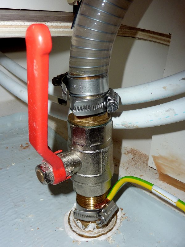
One installation I commonly see is a ball valve threaded directly onto a thru-hull as many production builders do for seacock installations. These builders very often display the NMMA & ABYC logo's proudly suggesting their vessels are built to meet the ABYC/NMMA safety standards.
In all fairness to the builders I suspect they believe these installations do or would meet the minimum safety standards but, as I found out, they certainly may not. Where is the in-house engineering by these builders who are violating the minimum strength requirements? Why do I have to be that guy who actually holds feet to fire? The manufacturers should be the ones ensuring these vessels meet the minimum standard before slapping the ABYC or NMMA sticker on the hull, but I digress....
I suppose we can't entirely blame the builders for installing the parts as "defined" in ABYC H-27 and then not having them meet the minimum standards? You would assume the manufacturers would have tested these fittings for the application into which they are sold but apparently they don't. ABYC leaves it up to them to prove "as installed"...
As I found out during testing a 3/4" Marine UL rated bronze valve threaded to a 3/4" Marine UL rated thru-hull fitting I purchased, does not meet ABYC H-27 Standards. It failed at 404 pounds and I was an 1 3/8" below the "innermost" hard piping so had slightly less leverage than I would have had I been able to apply the load at the absolute innermost "hard piping". This 3/4" installation should have easily handled 500 pounds for 30 seconds if it were to meet the minimum ABYC H-27 strengths standard. I have tested up to 1.25" in both bronze and Marelon. Marelon never got close. This 3/4" bronze thru-hull fitting was not the only seacock asembly I tested to not meet the standards. I also had Marelon valves also fail well below the minimum.
The good news is that the Marelon OEM / 93 Series does meet the standard as do every bronze flanged seacock I tested. In the case of an inexpensive Groco bronze flanged seacock it easily exceeded the standard by 300+ pounds.
Interestingly enough my findings are not alone, John Cly at Groco engineering concurred with me that this type of application, in multiple sizes *(I found the same), will not meet the H-27 standard. The found this in their own in-house testing too.
What does all this mean?
Does this test mean your seacocks will fail in normal use? Probably not, but we had one fail on us when a spare alternator slid across a shelf and hit the in-board end of the assembly so it can/could potentially happen. It happened to us back in the 90's. That single event is what prompted my entire diatribe on "proper seacock" installations etc.. It was a real wake up call for me..
My point here is that when buying a boat with this type of installation, for SIX to SEVEN figures, please be aware of, and know, that it is, and could be, a potential week point that may not meet the minimum ABYC or NMMA standards for seacocks and thru-hull fittings, at least in the 3/4" to 1.25" size ranges, the most common sizes....
What the ABYC definitions mean:
27.4.4 Seacock - A type of valve used to control intake or discharge of water through the hull. It is operated by a lever type handle usually operating through a 90° arc, giving a clear indication of whether it is open or shut, and is typically of the two following types:
27.4.4.1 Flanged Sea Valve – A Seacock with an integral flange used to individually and securely mount the device directly to the boat hull structure.
27.4.4.2 In Line Ball Valve – A Seacock designed to be supported entirely by the through-hull fitting.
Some key points of ABYC H-27:
27.5.1 All piping, tubing, or hose lines penetrating the hull below the maximum heeled waterline, shall be equipped with a seacock to stop the admission of water in the event of failure of pipes, tubing, or hose.
27.5.4 Seacocks shall be designed and constructed to meet ANSI/UL 1121, Marine Through-Hull Fittings and Sea-Valves.
27.5.5 Thru-hull fittings shall be designed and constructed to meet ANSI/UL 1121, Marine Through-Hull Fittings and Sea-Valves.
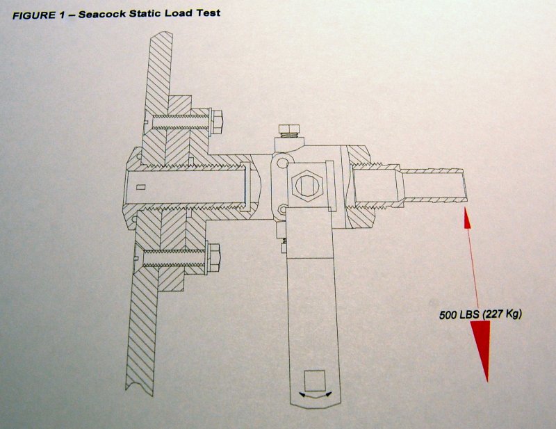
27.6.1 A seacock shall be securely mounted so that the assembly will withstand a 500 pound (227 Kg) static force applied for 30 seconds to the inboard end of the assembly, without the assembly failing to stop the ingress of water.
27.6.1.1 The installation shall prevent any movement of the assembly.
27.6.1.3 Threads used in seacock installations shall be compatible (eg. NPT to NPT, NPS to NPS).
The Tests:
The tests were performed in my shop using the work bench as the test jig. I was planning to rig up some 5/8" thick fiberglass and bolting it to the bench using some big backing plates. After running some numbers it appeared the 3/4" plywood should handle the loads, and it did.
I initially started by just inserting the seacock into a hole in the bench but moved to an elevated sheet of 1/2" GPO-3 polyester resin infused fiberglass sheet. The elevated sheet allowed for better viewing of what was under the "hull" and any flex or other abnormalities..
I use a calibrated digital load cell to measure the load being gradually applied to the seacock. The load was measured in pounds and was initially set to capture the moment of failure or "peak hold". I later switched to actual load due to line stretch and knots slipping. I eventually got a good system using lower stretch Dynema and Vectran line, though they don't like knots and the knots slip too..
To apply the load I used an old Lewmar self tailing winch attached to the end of the work bench. The load was applied as gradually as possible. The line was attached to the seacock assembly at the innermost hard piping above the imaginary hull.. It should be noted that this was not at the innermost portion of the hard piping, as it technically should be. I was always slightly below that point as I had no way to guarantee the line would hold there. This slightly lower pull position favors the seacock assembly slightly.
TEST #1
This video, as are all of them, is straight out of the camera, unedited. I apologize for the load not being visible on camera until the thru-hull snapped. I did use the "peak hold" feature to capture the exact load when failure occurred. I shoot unedited so there are no questions.
The bench:

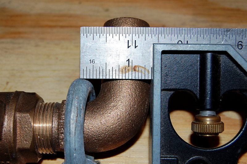
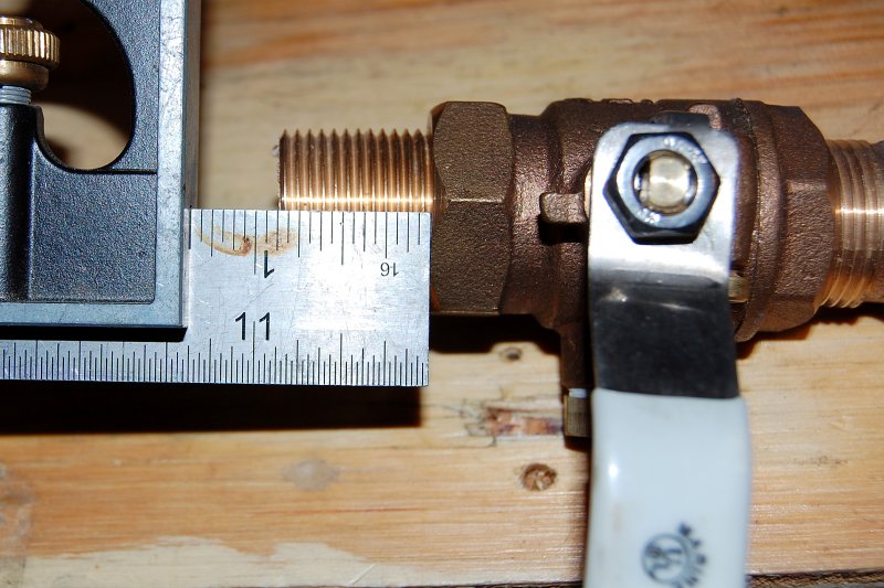
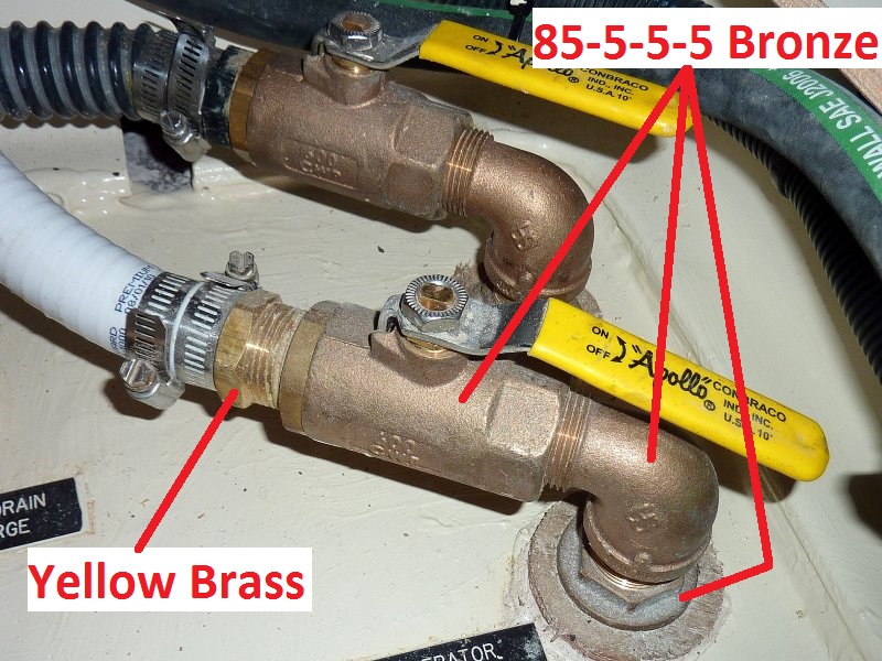
The materials are all "off the shelf" and purchased from Hamilton Marine in Portland, ME. To mimic what a boat owner or yard may install the materials are a mix of what was on hand at the chandlery. The bronze UL Marine thru-hull fitting was made by Apollo/Conbraco, the UL Marine valve by Groco and the bronze elbow was also by Groco.
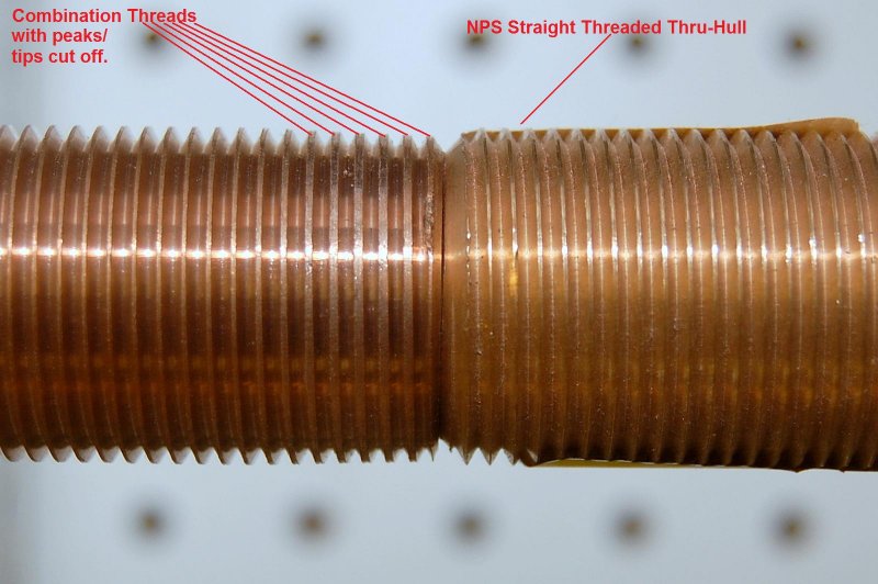
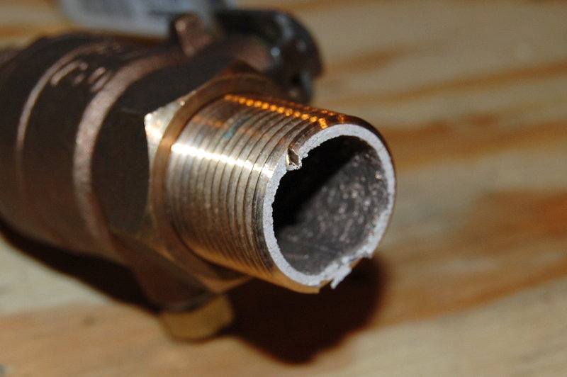
The thru-hull was fitted to my bench and tightened down well using a spud wrench. The valve was then threaded onto it and the elbow threaded into the valve. The ball valve to thru-hull is a known thread mismatch, NPS to NPT, (another violation of ABYC H-27) but what is very often done by builders, boat yards and DIY's. I wanted to mimic a real world type installation and most, at least in bronze, are of mixed parts, not just one brand. It was not the thread mismatch that failed.
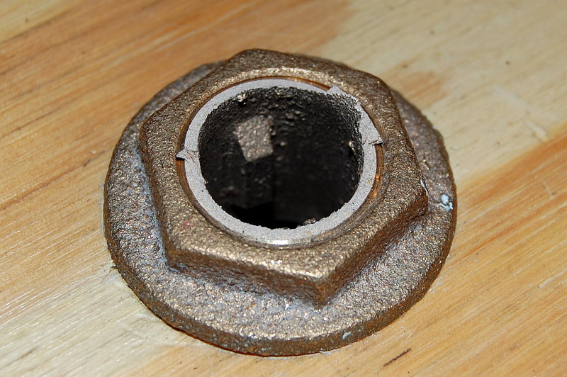
The 3/4" thru-hull failed at 404 pounds while trying to get to the 500 pounds and let it hold for 30 seconds. It never even made it to the ABYC minimum..
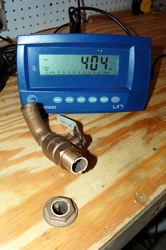
It failed flush with the nut.
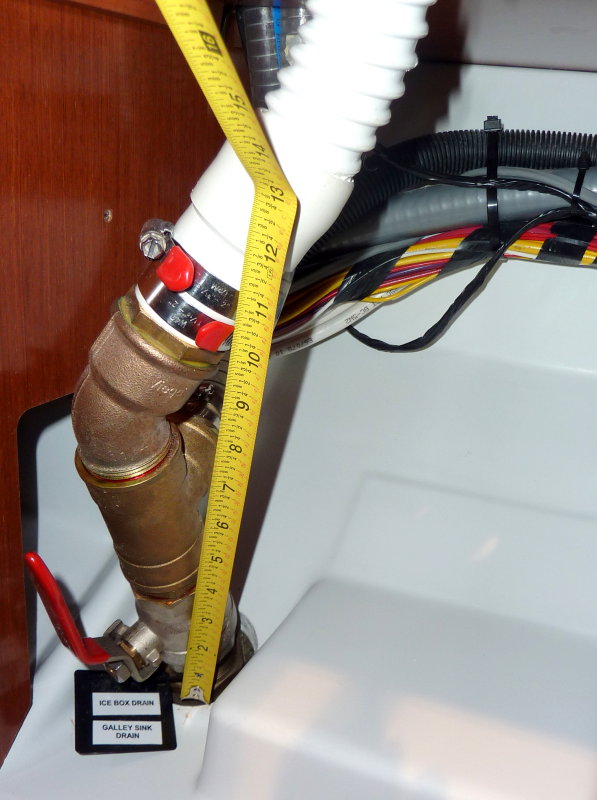
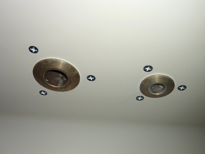
This was taken at the 2011 New England Boat Show on a brand new vessel which is supposed to be built to NMMA and ABYC standards...
Think about being knocked down off shore in rough weather, losing the cabin sole cover board, which had no dogs to keep it in place, and stepping directly onto one of these while being tossed around in rough weather.. Food for thought any way. These seacocks were located at the base of the companionway stairs. This makes for GREAT access but a poor place for the potential to land on one if that floor board gets tossed in a knock down. Positive locking "dogs" on the cabin sole would go a long way to making this a much safer installation.
Test #2
Next I tested a 3/4" Marelon valve on a 3/4" Marelon thru-hull with a 90 degree Marelon male adapter. Many builders pumped boats out with this exact installation in the 80's and 90's. This is a late 80's higher end production boat with this exact set up:
The load or pull point with the Marelon set up was applied at 4 1/4" off the bench. The load or pull point for the bronze set up was 4 3/4" off the bench. This was a 1/2" difference in FAVOR of Marelon yet it still failed at less than half the applied load.
I have left the video unedited from start to finish.. Please ignore the commentary as that was not planned. I was however shocked at the low failure load and apparently could not help editorializing.....") Many boat builders used this exact installation for years. There are ten of thousands of boats out there with this set up. Please be careful if you have this type of installation.
Many boat builders used this exact installation for years. There are ten of thousands of boats out there with this set up. Please be careful if you have this type of installation.
Test #3
Forespar saw my work and sent me a 3/4" OEM Series 93 Seacock, and thru-hull, to load test. The OEM/93 Series valve passed with flying colors! These are the valves that come standard on the vast majority of boats today as factory installed seacocks. The are a very good valve.
Unfortunately Forespar has not made them easily available to end users as they use a completely different thru-hull fitting and threads. Suffice it to say that if you have these valves they are very robust! Be glad your builder used them. These valves can be ordered for a retrofit and would be my recommendation if using non-metallic Marelon valves.
It should be noted that the 93 Series uses an entirely different thread and thru-hull fitting than do the Marelon ball valves or the Marelon tri-flange seacocks. This thru-hull fitting is significantly thicker and much stronger.
Test #4
This test has little to do with anything but drilling and tapping the backing block rather than drilling entirely through the hull of the boat for the seacock flange. Some boaters are adamant they don't want any more holes in the hull so I offered this option.
I originally posted this as; " Alternative Method Backing Blocks" on my web site for those who do not want to drill yet more holes entirely through the hull. On my site I recommend using 5/8" GPO-3 or 5/8" G-10 polyester/fiberglass or epoxy/fiberglass sheet.
For this test I used 1/2" GPO-3 polyester/fiberglass sheet. GPO-3 is very strong and G-10 is even stronger. GPO-3 is polyester resin/fiberglass and G-10 is epoxy resin/fiberglass.
One reader of my site emailed me, with concern, that if you hit something and lost the thru-hull the bolts would simply pull right out of the fiberglass sheet and you would sink. His take was that the bolts are a weak link when drilled & tapped into a 5/8" G-10 or GPO-3 backing block. Having tested this, well before I ever recommended it as an "alternative" option, I knew that to not be the case.
To mimic this mythical event, losing only the thru-hull fitting but not punching a hole in the boat in the process, I did not install the thru-hull. Instead relied solely on the three 1/4" X 20 machine screws to hold the seacock into the GPO-3 board.
So which was stronger a 3/4" Marelon tri-flange seacock or the 1/4 X 20 machine screws tapped into the 1/2" fiberglass sheet?
Disclaimer: It should be noted that the thru-hull is an integral part of the strength of the seacock assembly. The video below is an "unfair" representation of the failure point of the Marelon tri-flange seacock because the thru-hull fitting was not installed. I do plan to destroy another valve identical to this one, only with the thru-hull installed. My guess is that it will meet the 500 pounds for 30 seconds.
Here we go:
Test #5
This test had three parts.
1- To test the strength of drilling and tapping directly into a 1/2" fiberglass board to see if it meets the ABYC standards.
2- To test a standard 3/4" Marelon ball valve to ABYC strength standards.
3- To test the strength of a Groco flanged adapter in 3/4".
Disclaimer: In fairness to Forespar this was an early Marelon valve that already had the handle fail. Why ruin a brand new valve, right? Still, in my opinion, the strength of the valve body should not have been compromised by the missing handle. With the video viewed frame by frame the valve failed & slipped the first thread at 253 pounds.. The ABYC standards call for 500 pounds at the innermost hard piping or male adapter for a period of 30 seconds. This particular valve, an older model, did not meet the standard but this is not to say a newer version would act the same.
Test #6
Again the goal for this test was to see how strong the bronze seacock was as well as the drill & tap method, just like above. This valve and the drill & tap method easily exceeded the ABYC strength standards by over 300 pounds WITHOUT a thru-hull installed.
DISCLAIMER: The valve would be even STRONGER had I been using the thru-hull fitting. Seeing as nothing failed and I stressed it to over 800 pounds no "disclaimer" is really necessary.
More to come, as I test them...
One installation I commonly see is a ball valve threaded directly onto a thru-hull as many production builders do for seacock installations. These builders very often display the NMMA & ABYC logo's proudly suggesting their vessels are built to meet the ABYC/NMMA safety standards.
In all fairness to the builders I suspect they believe these installations do or would meet the minimum safety standards but, as I found out, they certainly may not. Where is the in-house engineering by these builders who are violating the minimum strength requirements? Why do I have to be that guy who actually holds feet to fire? The manufacturers should be the ones ensuring these vessels meet the minimum standard before slapping the ABYC or NMMA sticker on the hull, but I digress....
I suppose we can't entirely blame the builders for installing the parts as "defined" in ABYC H-27 and then not having them meet the minimum standards? You would assume the manufacturers would have tested these fittings for the application into which they are sold but apparently they don't. ABYC leaves it up to them to prove "as installed"...
As I found out during testing a 3/4" Marine UL rated bronze valve threaded to a 3/4" Marine UL rated thru-hull fitting I purchased, does not meet ABYC H-27 Standards. It failed at 404 pounds and I was an 1 3/8" below the "innermost" hard piping so had slightly less leverage than I would have had I been able to apply the load at the absolute innermost "hard piping". This 3/4" installation should have easily handled 500 pounds for 30 seconds if it were to meet the minimum ABYC H-27 strengths standard. I have tested up to 1.25" in both bronze and Marelon. Marelon never got close. This 3/4" bronze thru-hull fitting was not the only seacock asembly I tested to not meet the standards. I also had Marelon valves also fail well below the minimum.
The good news is that the Marelon OEM / 93 Series does meet the standard as do every bronze flanged seacock I tested. In the case of an inexpensive Groco bronze flanged seacock it easily exceeded the standard by 300+ pounds.
Interestingly enough my findings are not alone, John Cly at Groco engineering concurred with me that this type of application, in multiple sizes *(I found the same), will not meet the H-27 standard. The found this in their own in-house testing too.
What does all this mean?
Does this test mean your seacocks will fail in normal use? Probably not, but we had one fail on us when a spare alternator slid across a shelf and hit the in-board end of the assembly so it can/could potentially happen. It happened to us back in the 90's. That single event is what prompted my entire diatribe on "proper seacock" installations etc.. It was a real wake up call for me..
My point here is that when buying a boat with this type of installation, for SIX to SEVEN figures, please be aware of, and know, that it is, and could be, a potential week point that may not meet the minimum ABYC or NMMA standards for seacocks and thru-hull fittings, at least in the 3/4" to 1.25" size ranges, the most common sizes....
What the ABYC definitions mean:
27.4.4 Seacock - A type of valve used to control intake or discharge of water through the hull. It is operated by a lever type handle usually operating through a 90° arc, giving a clear indication of whether it is open or shut, and is typically of the two following types:
27.4.4.1 Flanged Sea Valve – A Seacock with an integral flange used to individually and securely mount the device directly to the boat hull structure.
27.4.4.2 In Line Ball Valve – A Seacock designed to be supported entirely by the through-hull fitting.
Some key points of ABYC H-27:
27.5.1 All piping, tubing, or hose lines penetrating the hull below the maximum heeled waterline, shall be equipped with a seacock to stop the admission of water in the event of failure of pipes, tubing, or hose.
27.5.4 Seacocks shall be designed and constructed to meet ANSI/UL 1121, Marine Through-Hull Fittings and Sea-Valves.
27.5.5 Thru-hull fittings shall be designed and constructed to meet ANSI/UL 1121, Marine Through-Hull Fittings and Sea-Valves.
27.6.1 A seacock shall be securely mounted so that the assembly will withstand a 500 pound (227 Kg) static force applied for 30 seconds to the inboard end of the assembly, without the assembly failing to stop the ingress of water.
27.6.1.1 The installation shall prevent any movement of the assembly.
27.6.1.3 Threads used in seacock installations shall be compatible (eg. NPT to NPT, NPS to NPS).
The Tests:
The tests were performed in my shop using the work bench as the test jig. I was planning to rig up some 5/8" thick fiberglass and bolting it to the bench using some big backing plates. After running some numbers it appeared the 3/4" plywood should handle the loads, and it did.
I initially started by just inserting the seacock into a hole in the bench but moved to an elevated sheet of 1/2" GPO-3 polyester resin infused fiberglass sheet. The elevated sheet allowed for better viewing of what was under the "hull" and any flex or other abnormalities..
I use a calibrated digital load cell to measure the load being gradually applied to the seacock. The load was measured in pounds and was initially set to capture the moment of failure or "peak hold". I later switched to actual load due to line stretch and knots slipping. I eventually got a good system using lower stretch Dynema and Vectran line, though they don't like knots and the knots slip too..
To apply the load I used an old Lewmar self tailing winch attached to the end of the work bench. The load was applied as gradually as possible. The line was attached to the seacock assembly at the innermost hard piping above the imaginary hull.. It should be noted that this was not at the innermost portion of the hard piping, as it technically should be. I was always slightly below that point as I had no way to guarantee the line would hold there. This slightly lower pull position favors the seacock assembly slightly.
TEST #1
This video, as are all of them, is straight out of the camera, unedited. I apologize for the load not being visible on camera until the thru-hull snapped. I did use the "peak hold" feature to capture the exact load when failure occurred. I shoot unedited so there are no questions.
The bench:
The materials are all "off the shelf" and purchased from Hamilton Marine in Portland, ME. To mimic what a boat owner or yard may install the materials are a mix of what was on hand at the chandlery. The bronze UL Marine thru-hull fitting was made by Apollo/Conbraco, the UL Marine valve by Groco and the bronze elbow was also by Groco.
The thru-hull was fitted to my bench and tightened down well using a spud wrench. The valve was then threaded onto it and the elbow threaded into the valve. The ball valve to thru-hull is a known thread mismatch, NPS to NPT, (another violation of ABYC H-27) but what is very often done by builders, boat yards and DIY's. I wanted to mimic a real world type installation and most, at least in bronze, are of mixed parts, not just one brand. It was not the thread mismatch that failed.
The 3/4" thru-hull failed at 404 pounds while trying to get to the 500 pounds and let it hold for 30 seconds. It never even made it to the ABYC minimum..
It failed flush with the nut.
This was taken at the 2011 New England Boat Show on a brand new vessel which is supposed to be built to NMMA and ABYC standards...
Think about being knocked down off shore in rough weather, losing the cabin sole cover board, which had no dogs to keep it in place, and stepping directly onto one of these while being tossed around in rough weather.. Food for thought any way. These seacocks were located at the base of the companionway stairs. This makes for GREAT access but a poor place for the potential to land on one if that floor board gets tossed in a knock down. Positive locking "dogs" on the cabin sole would go a long way to making this a much safer installation.
Test #2
Next I tested a 3/4" Marelon valve on a 3/4" Marelon thru-hull with a 90 degree Marelon male adapter. Many builders pumped boats out with this exact installation in the 80's and 90's. This is a late 80's higher end production boat with this exact set up:
The load or pull point with the Marelon set up was applied at 4 1/4" off the bench. The load or pull point for the bronze set up was 4 3/4" off the bench. This was a 1/2" difference in FAVOR of Marelon yet it still failed at less than half the applied load.
I have left the video unedited from start to finish.. Please ignore the commentary as that was not planned. I was however shocked at the low failure load and apparently could not help editorializing.....
Many boat builders used this exact installation for years. There are ten of thousands of boats out there with this set up. Please be careful if you have this type of installation.Test #3
Forespar saw my work and sent me a 3/4" OEM Series 93 Seacock, and thru-hull, to load test. The OEM/93 Series valve passed with flying colors!
These are the valves that come standard on the vast majority of boats today as factory installed seacocks. The are a very good valve.Unfortunately Forespar has not made them easily available to end users as they use a completely different thru-hull fitting and threads. Suffice it to say that if you have these valves they are very robust! Be glad your builder used them. These valves can be ordered for a retrofit and would be my recommendation if using non-metallic Marelon valves.
It should be noted that the 93 Series uses an entirely different thread and thru-hull fitting than do the Marelon ball valves or the Marelon tri-flange seacocks. This thru-hull fitting is significantly thicker and much stronger.
Test #4
This test has little to do with anything but drilling and tapping the backing block rather than drilling entirely through the hull of the boat for the seacock flange. Some boaters are adamant they don't want any more holes in the hull so I offered this option.
I originally posted this as; " Alternative Method Backing Blocks" on my web site for those who do not want to drill yet more holes entirely through the hull. On my site I recommend using 5/8" GPO-3 or 5/8" G-10 polyester/fiberglass or epoxy/fiberglass sheet.
For this test I used 1/2" GPO-3 polyester/fiberglass sheet. GPO-3 is very strong and G-10 is even stronger. GPO-3 is polyester resin/fiberglass and G-10 is epoxy resin/fiberglass.
One reader of my site emailed me, with concern, that if you hit something and lost the thru-hull the bolts would simply pull right out of the fiberglass sheet and you would sink. His take was that the bolts are a weak link when drilled & tapped into a 5/8" G-10 or GPO-3 backing block. Having tested this, well before I ever recommended it as an "alternative" option, I knew that to not be the case.
To mimic this mythical event, losing only the thru-hull fitting but not punching a hole in the boat in the process, I did not install the thru-hull. Instead relied solely on the three 1/4" X 20 machine screws to hold the seacock into the GPO-3 board.
So which was stronger a 3/4" Marelon tri-flange seacock or the 1/4 X 20 machine screws tapped into the 1/2" fiberglass sheet?
Disclaimer: It should be noted that the thru-hull is an integral part of the strength of the seacock assembly. The video below is an "unfair" representation of the failure point of the Marelon tri-flange seacock because the thru-hull fitting was not installed. I do plan to destroy another valve identical to this one, only with the thru-hull installed. My guess is that it will meet the 500 pounds for 30 seconds.
Here we go:
Test #5
This test had three parts.
1- To test the strength of drilling and tapping directly into a 1/2" fiberglass board to see if it meets the ABYC standards.
2- To test a standard 3/4" Marelon ball valve to ABYC strength standards.
3- To test the strength of a Groco flanged adapter in 3/4".
Disclaimer: In fairness to Forespar this was an early Marelon valve that already had the handle fail. Why ruin a brand new valve, right? Still, in my opinion, the strength of the valve body should not have been compromised by the missing handle. With the video viewed frame by frame the valve failed & slipped the first thread at 253 pounds.. The ABYC standards call for 500 pounds at the innermost hard piping or male adapter for a period of 30 seconds. This particular valve, an older model, did not meet the standard but this is not to say a newer version would act the same.
Test #6
Again the goal for this test was to see how strong the bronze seacock was as well as the drill & tap method, just like above. This valve and the drill & tap method easily exceeded the ABYC strength standards by over 300 pounds WITHOUT a thru-hull installed.
DISCLAIMER: The valve would be even STRONGER had I been using the thru-hull fitting. Seeing as nothing failed and I stressed it to over 800 pounds no "disclaimer" is really necessary.
More to come, as I test them...