Repairing Hunter 40 damage from Hurricane Matthew
- Thread starter B757Captain
- Start date
Stand by for the next reading!Can you put sound insulation around the outside of the box?
There should not be any issues with overheating of any of the marine a/c units that I know of. Most all the separate components don't of themselves generate much heat except for the condenser coil coming from the compressor. On mine that part of exposed piping prior to the raw water coil is insulated, and of course the heat generated from the freon itself is cooled by raw water. The only other thing I can think of that might be affected would be the orifice tube (mostly on older design units - most newer ones have expansion valves) but mine is chugging away nicely snugged inside its new enclosure.Interesting, I never knew I could enclose the a/c units to reduce sound. I just assumed that would cause some kind of over heating problem. Thanks Mark you just may have made my wife happy; assuming I have 1/4 your skills and can figure out how to enclose the units.
I say go for it!

Finalizing the air conditioning, Part 2:
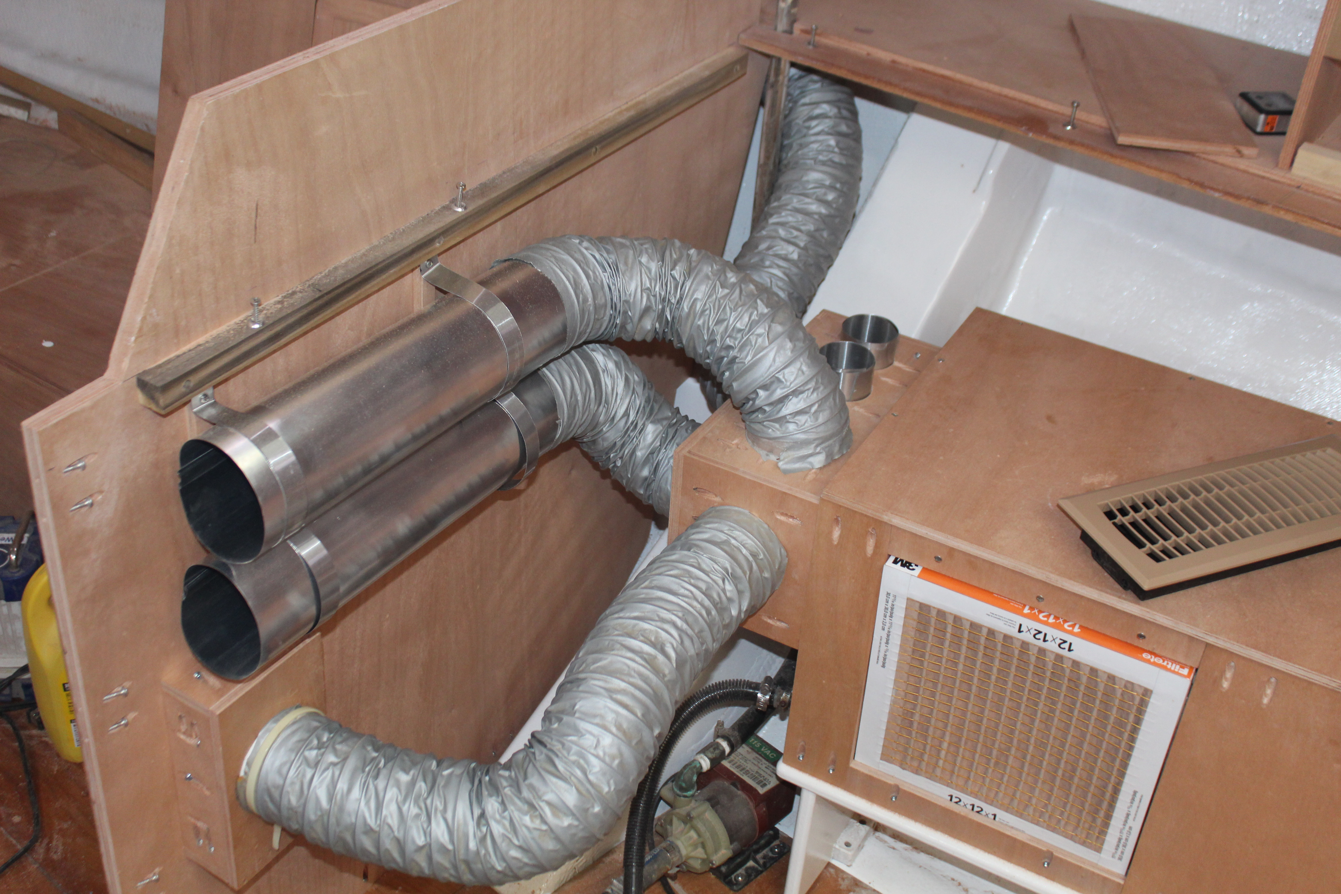
With the enclosure built and the outlet boxed it's time to think about the distribution manifold. Flagship sends an aluminum attachment that fits over the outlet which the ducting is attached to. This worked ok on my old unit but since the new one has a 45 degree angled outlet it won't work well. The old setup had four 4" outlets but on the new unit they upgraded the fan and motor for more cfm output so 5 outlets are required now.
I started by digging all my old ducting, registers, tees, etc. out of the attic and doing a little inventory:
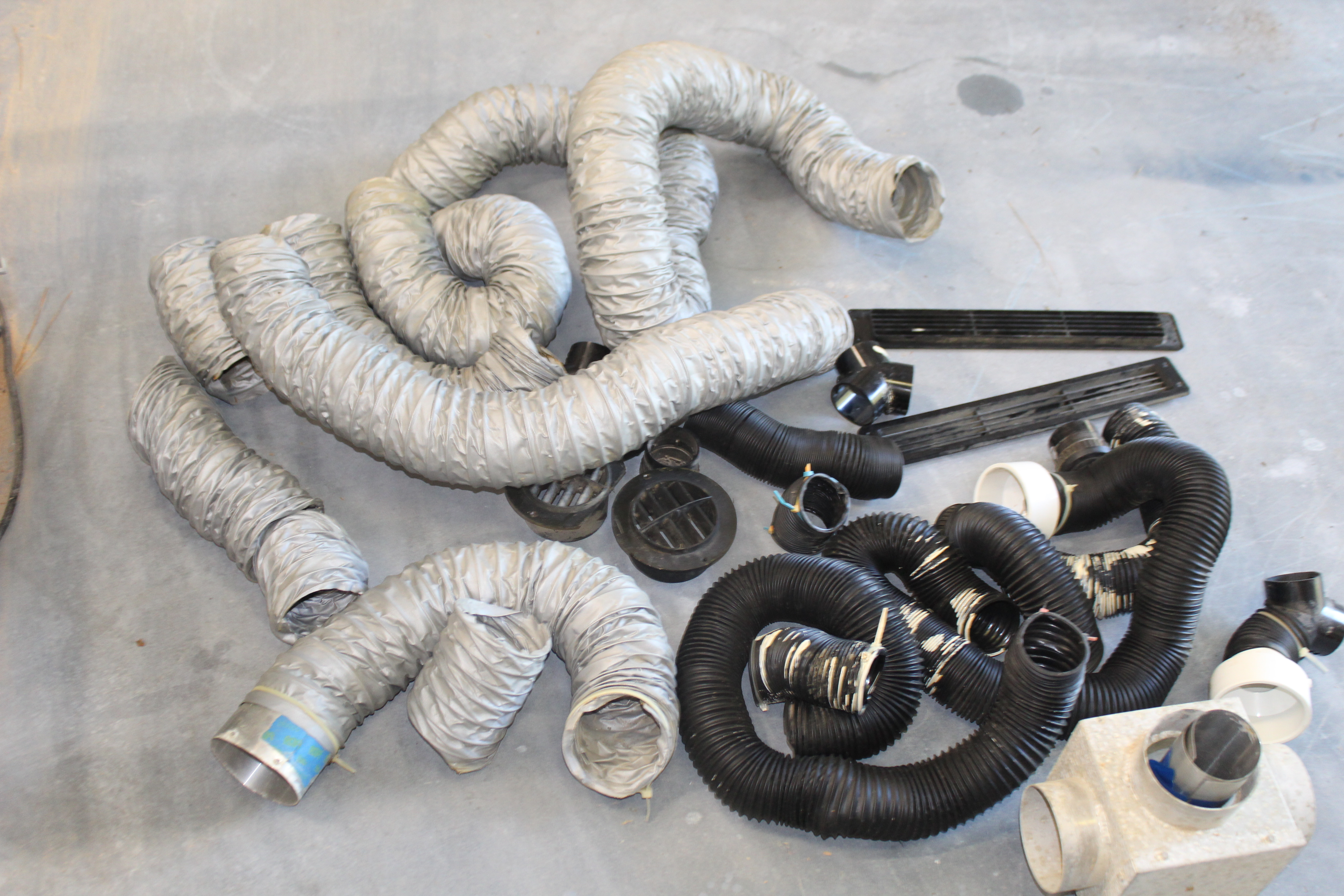
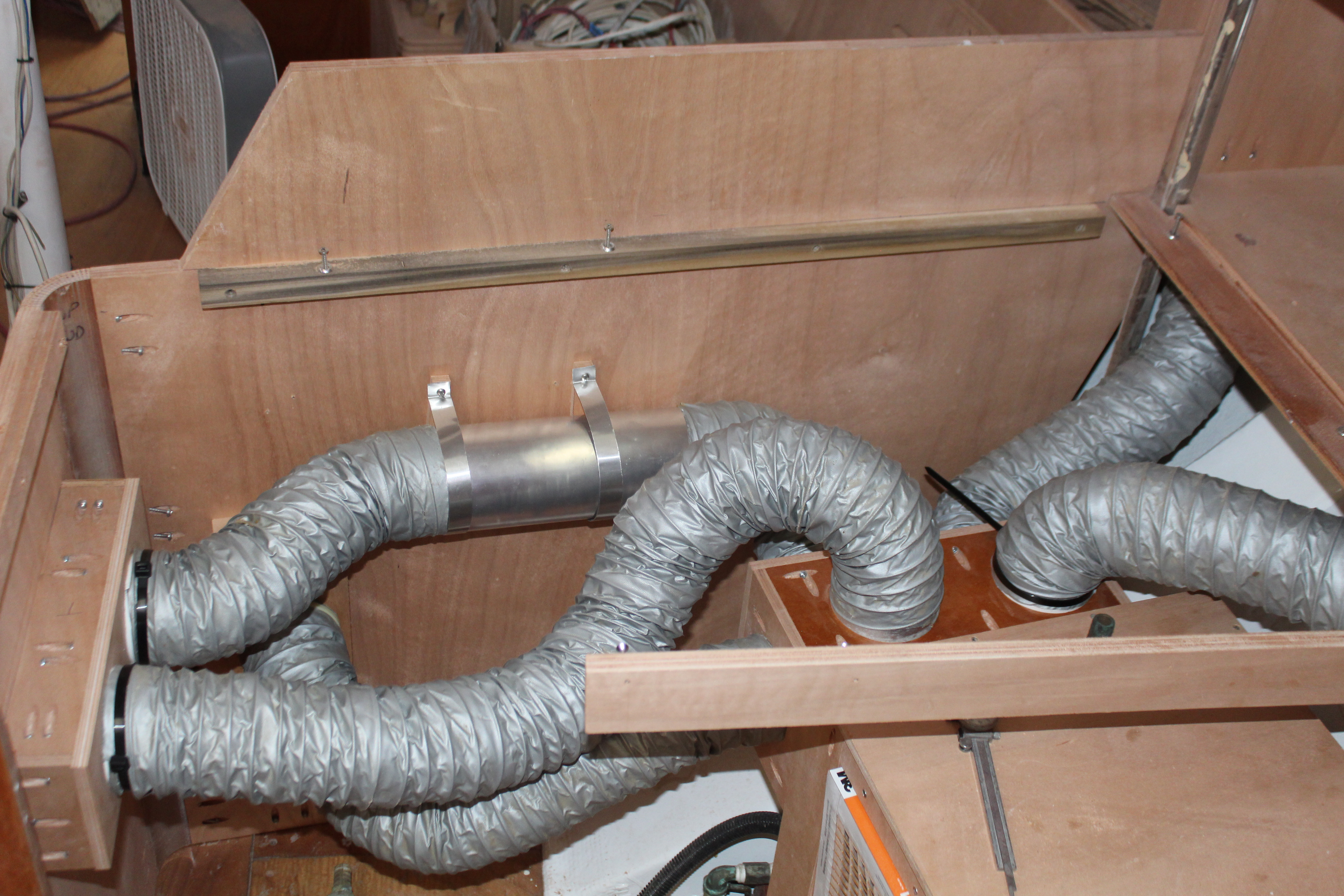
The silvery pieces are the 4" hoses, the black ones are 2 1/2" hoses. I routed the smaller hoses forward to the head and v-berth and aft to the aft cabin. In the lower right of the pic you can see the old aluminum manifold. I worked on a little (hopefully) better setup and made this:
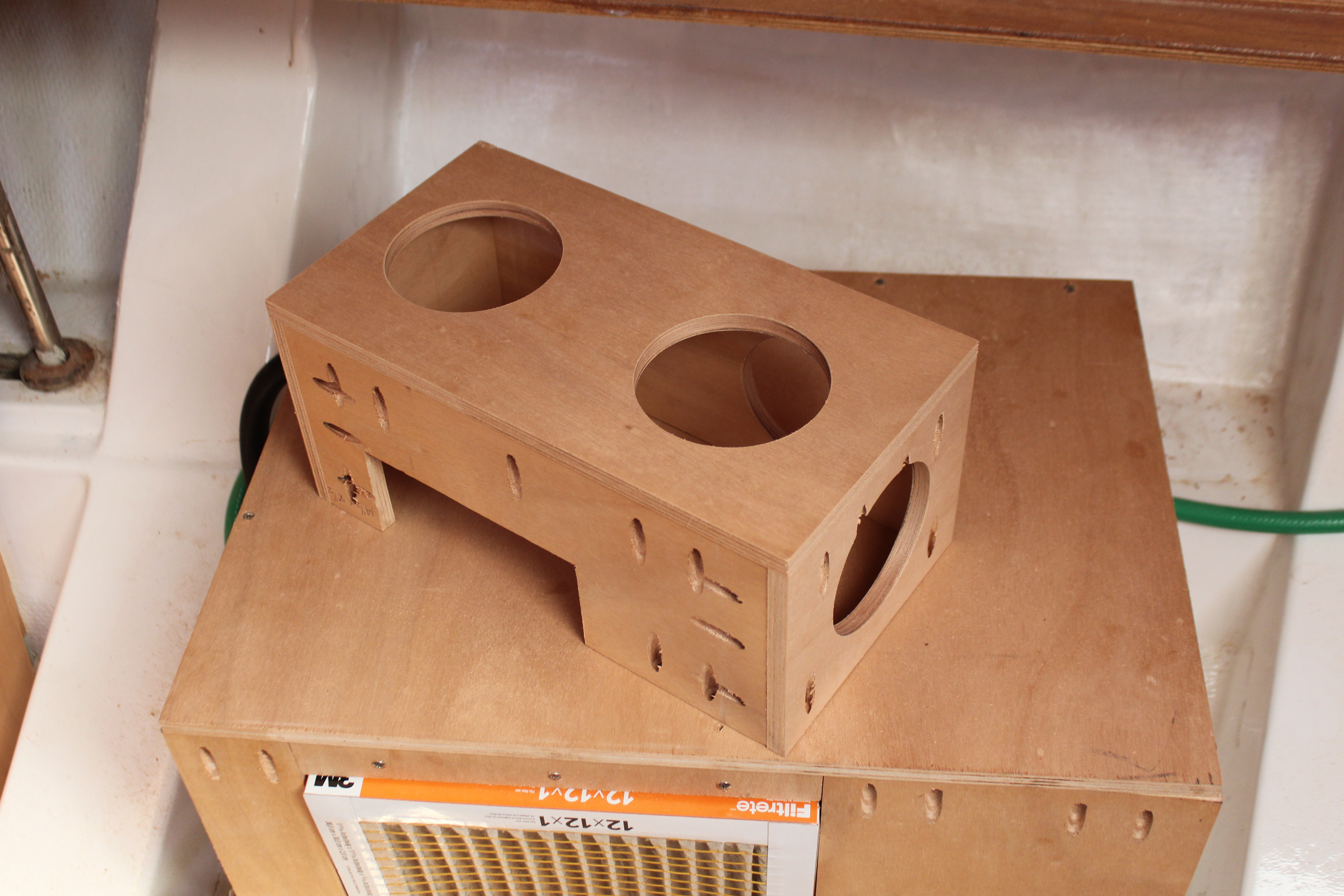
I cut the welds for the aluminum rings off the old manifold and mounted them in the new:
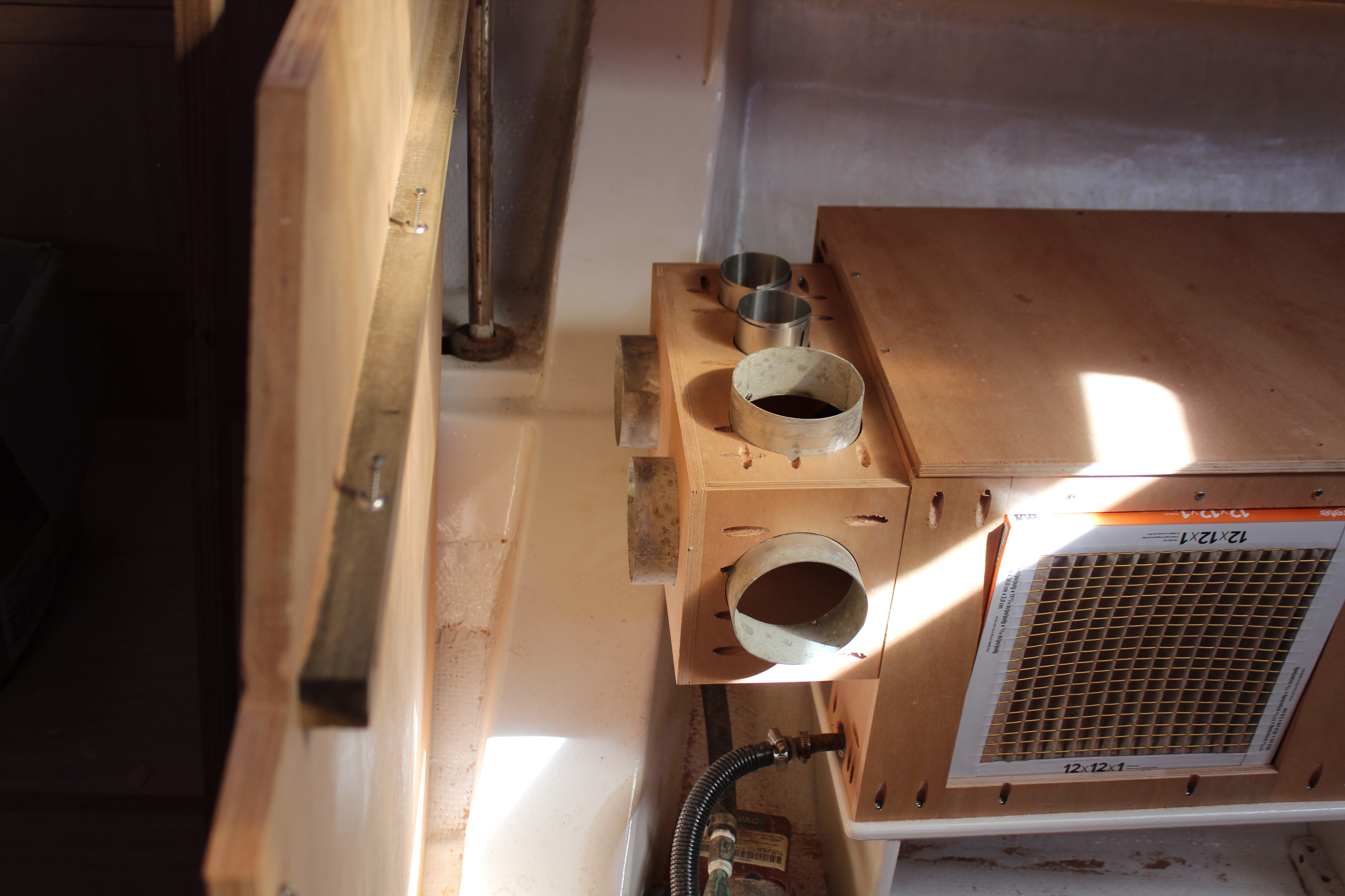
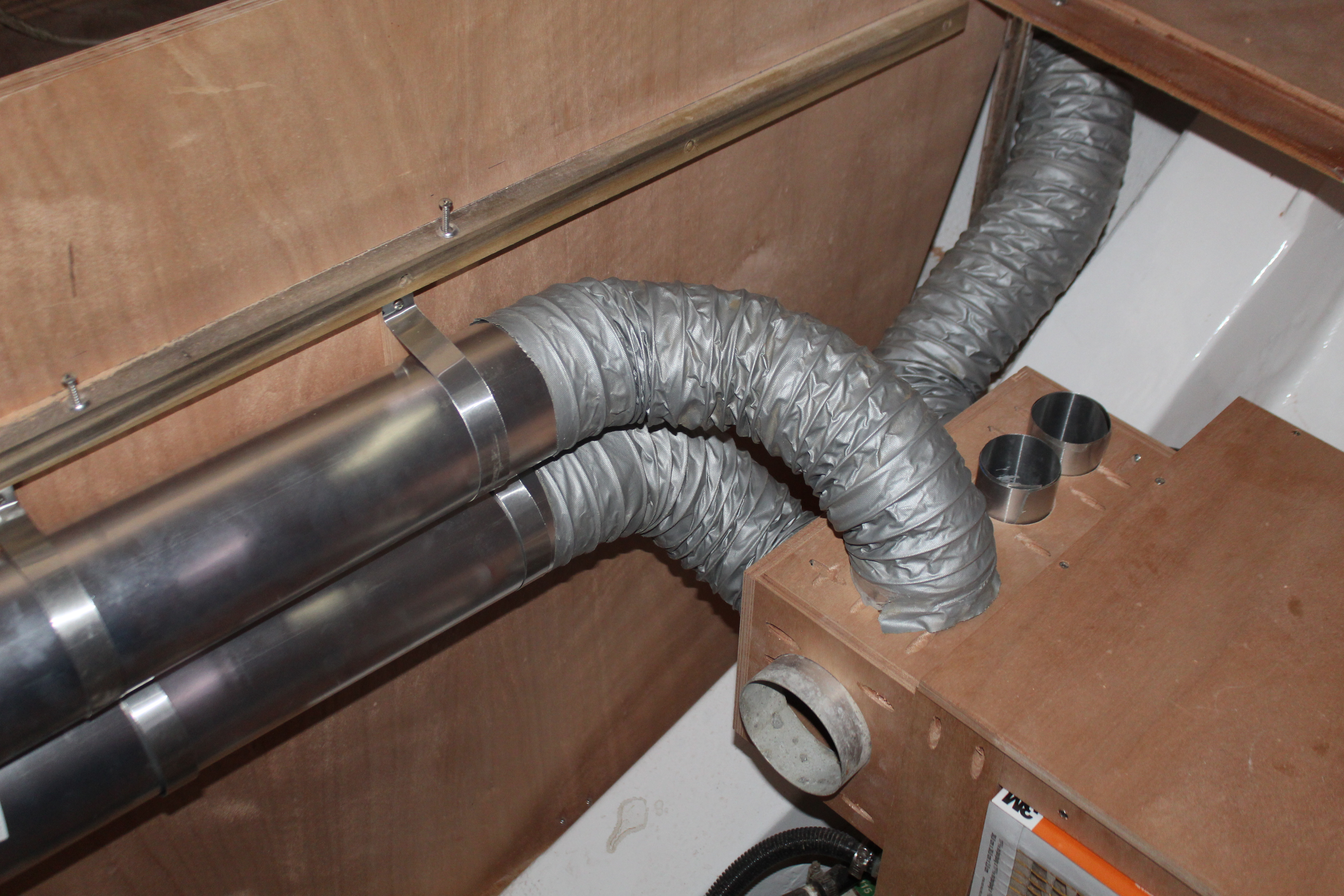
So I've now got four 4" duct outlets and two 2 1/2" outlets. Should be enough. Turned out not to be the case but for unexpected reasons. In the meantime I got the manifold mounted to the side of the enclosure - working and so far, so good. I routed the hoses and ducting forward to the v-berth and forward head and started hooking things up, as well as planning for the routing of the ducting for the main cabin:
I re-used the 2 1/2" registers forward (I got them years ago from a company called Vintage Air - they specialize in add-on a/c for classic cars). The old 4" registers were round black things that I have always thought were eye-sores so I started looking for alternatives. Square teak registers are available from the usual marine outlets but - OMG! - I am not paying those prices for a little bling!
A tour through the aisles of the local Lowes and I came up with these:
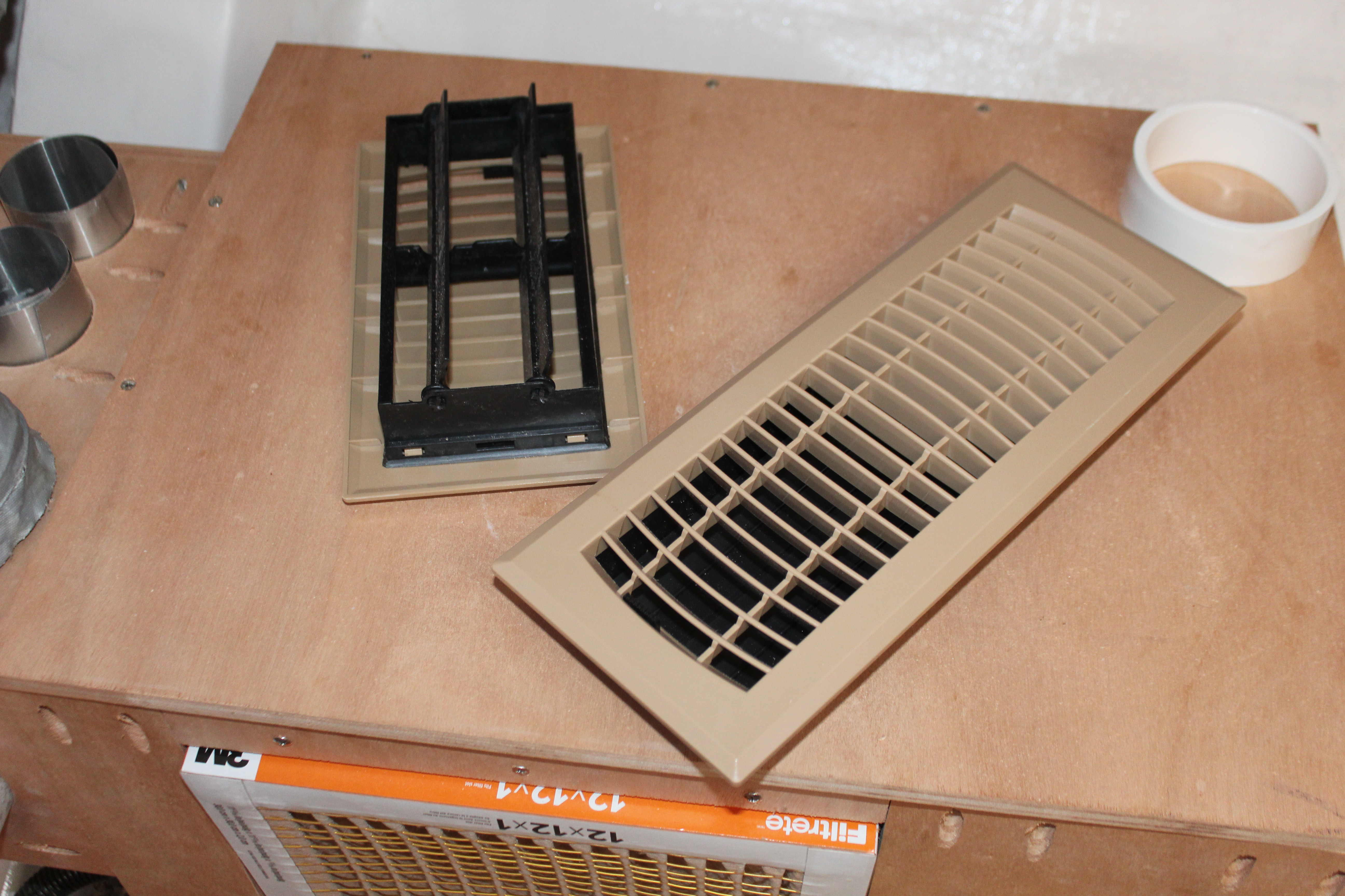
They are actually floor registers but I couldn't find any wall or ceiling registers with plastic construction - definitely don't want the ones made from galvanized! I did find some with red oak faces but still debating the added cost. For now these will do.
Next up, finishing up.
Cheers,
Mark
With the enclosure built and the outlet boxed it's time to think about the distribution manifold. Flagship sends an aluminum attachment that fits over the outlet which the ducting is attached to. This worked ok on my old unit but since the new one has a 45 degree angled outlet it won't work well. The old setup had four 4" outlets but on the new unit they upgraded the fan and motor for more cfm output so 5 outlets are required now.
I started by digging all my old ducting, registers, tees, etc. out of the attic and doing a little inventory:
The silvery pieces are the 4" hoses, the black ones are 2 1/2" hoses. I routed the smaller hoses forward to the head and v-berth and aft to the aft cabin. In the lower right of the pic you can see the old aluminum manifold. I worked on a little (hopefully) better setup and made this:
I cut the welds for the aluminum rings off the old manifold and mounted them in the new:
So I've now got four 4" duct outlets and two 2 1/2" outlets. Should be enough. Turned out not to be the case but for unexpected reasons. In the meantime I got the manifold mounted to the side of the enclosure - working and so far, so good. I routed the hoses and ducting forward to the v-berth and forward head and started hooking things up, as well as planning for the routing of the ducting for the main cabin:
I re-used the 2 1/2" registers forward (I got them years ago from a company called Vintage Air - they specialize in add-on a/c for classic cars). The old 4" registers were round black things that I have always thought were eye-sores so I started looking for alternatives. Square teak registers are available from the usual marine outlets but - OMG! - I am not paying those prices for a little bling!
A tour through the aisles of the local Lowes and I came up with these:
They are actually floor registers but I couldn't find any wall or ceiling registers with plastic construction - definitely don't want the ones made from galvanized! I did find some with red oak faces but still debating the added cost. For now these will do.
Next up, finishing up.
Cheers,
Mark
This the first time I have looked at Marks work and thought. "Not too sure about that."
The set up with ducting at the airflow outlet and a shroud around the condenser should be fine for cooling.
However, the filter in front of the condenser coil not a good idea. A grill made of wood slats is the norm and adds almost no resistance to airflow.
Don't worry too much about grime build up on the condenser fins. No commercial unit has a filter there.
I am a qualified Refrigeration Mechanic.
gary
The filter is sitting in front of the evaporator - the condenser coils are on the opposite side of the unit. FM recommends that an intake filter be used for the incoming air wherever the unit is mounted, though I probably have it much closer than they envisionedThis the first time I have looked at Marks work and thought. "Not too sure about that."
The set up with ducting at the airflow outlet and a shroud around the condenser should be fine for cooling.
However, the filter in front of the condenser coil not a good idea. A grill made of wood slats is the norm and adds almost no resistance to airflow.
Don't worry too much about grime build up on the condenser fins. No commercial unit has a filter there.
I am a qualified Refrigeration Mechanic.
gary
. I have alternated over the years between having a filter and not - and the fins on the evaporator can get clogged mightily without it and are a right PITA to clean.When the boat reverts from a construction zone to a cruising vessel I'll revisit the need for the filter
, but for now I will keep it, if for no other reason than to filter the dust and sawdust moving through the a/c (and thus the output air). I have already changed the filter once and boy, did it do it's job! I will need to increase the filter size but smaller filters are hard to find.
Last edited:
Cut one 12x12 in half, combine to make a 12x18, and use Duct tape to seal the cut edge against your box.I will need to increase the filter size but smaller filters are hard to find
Tip: Inlet air filter Area should 2 times the combined exit flow areas.
Jim...
PS: Cut to fit, tape to match.
Finalizing the air conditioning, finally!:
My original idea of running two 2 1/2" ducts to the aft cabin came to a screeching halt when I realized that (a): I didn't have enough hose to do that and (b): the place I originally bought the 2 1/2" stuff from no longer sells retail and (c): the only other place to get 2 1/2" hose was too spendy. So . . . I had enough 4" hose left to plumb the aft cabin, but I needed to replace part of the manifold where the two 2 1/2" holes were cut. I carefully measured a new side to the manifold and proceeded to fully prep it. Once all the holes, screw holes, etc., were cut I found out that the new piece didn't even come close to fitting! Too long on one side, and too narrow on the other side . Hmm. Obviously a victim of measure once, cut twice. As I'm contemplating this screw-up I glanced to the side and saw the actual replacement piece I initially cut, not the random piece I picked up and worked on by mistake . No worries, repeat the process on the correct piece and press on. I have intentionally not posted that picture (for obvious reasons ).
Next up, the new registers. The old round junky black eye-sores - oops, registers - were easy to install, just cut a 4" hole wherever you feel like and pop 'em in. Since I'm replacing them I had to get respectable and mount and duct them properly, so another trip to the scrap plywood pile was in order:
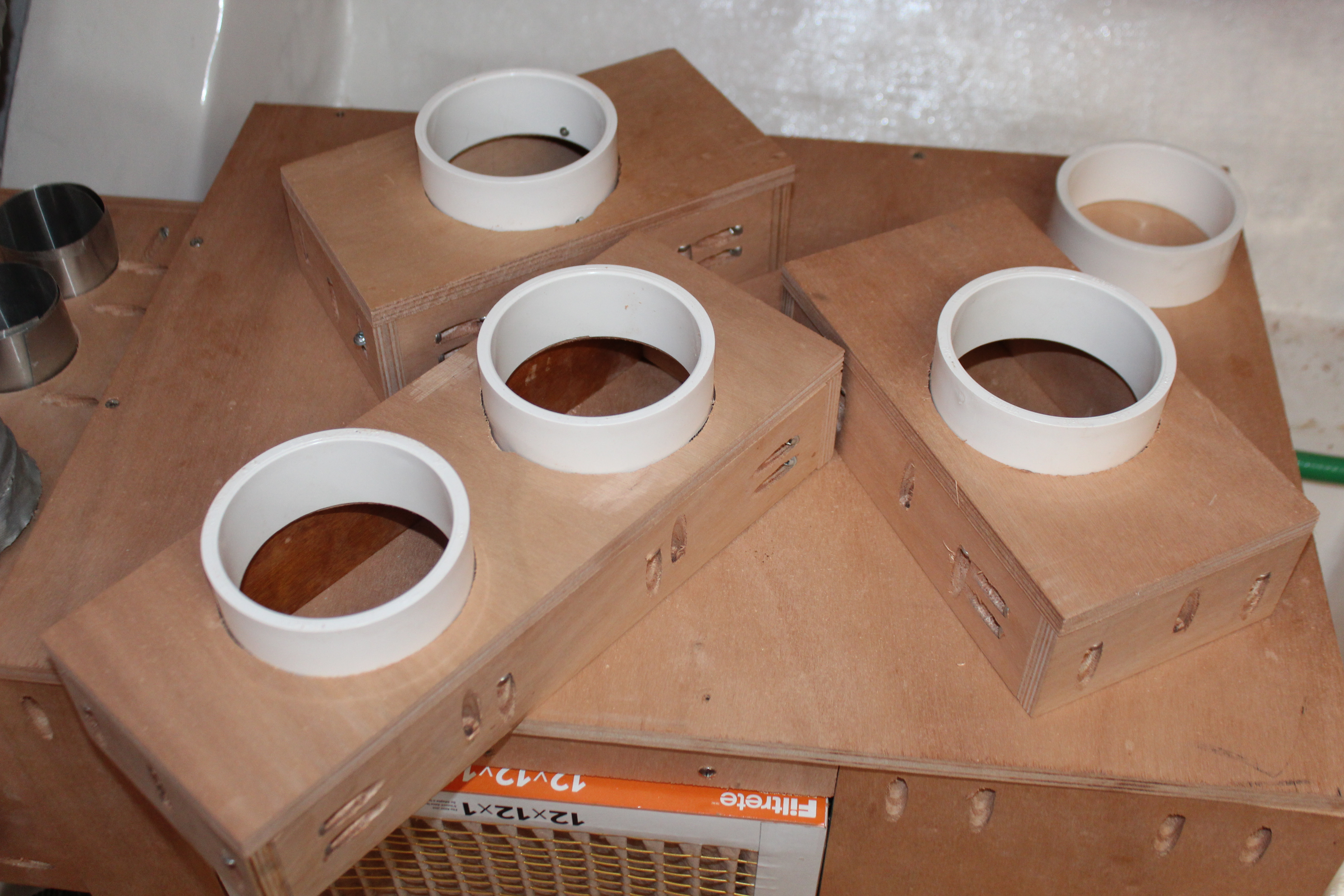
I'm mounting one 4"x8" register in the aft cabin and a 4"x8" and a 4"x12" in the main cabin. A 4" OD PVC coupler and a trip through the table saw gave me the collars since I was out of aluminum collars. Here's the first duct mounted:
and the aft cabin:
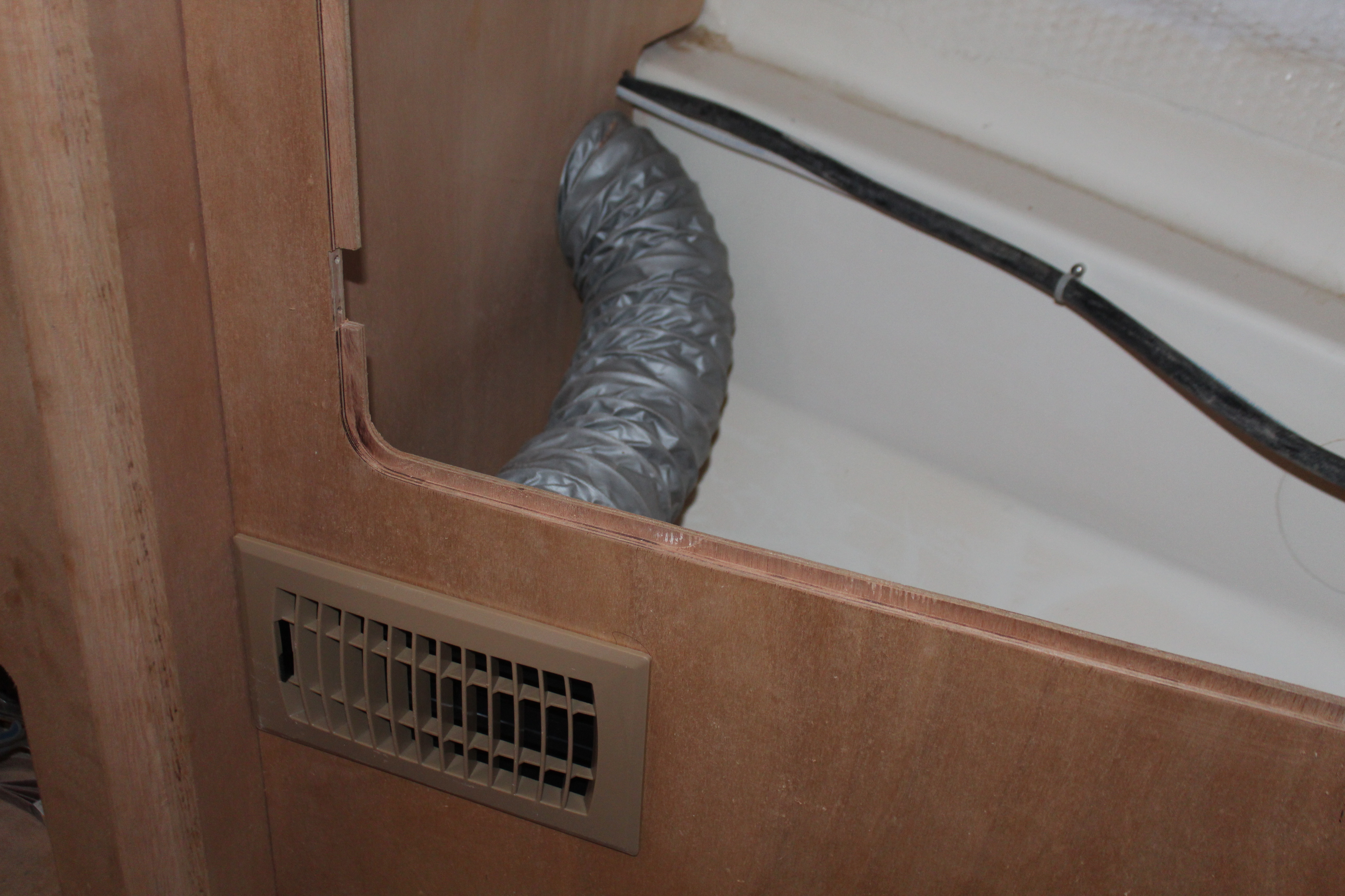
And the ducting for the 4"x12" register. I did have to rethink some of the ducting since the sink and relevant plumbing has to occupy some of the same space as the a/c ducting:
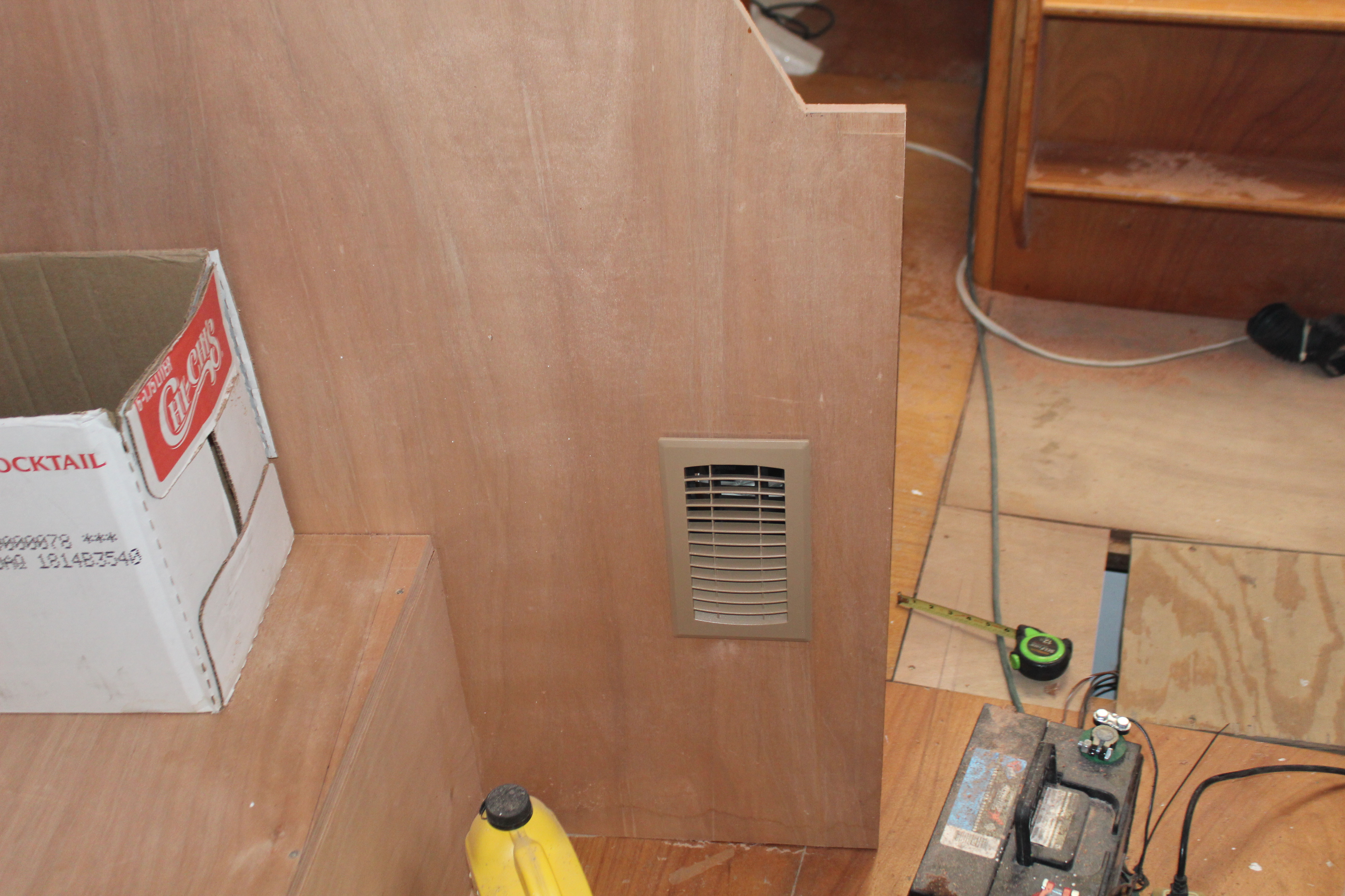
Finally done! For now anyway - when I blow the galley back apart I will paint, seal and insulate everything. But on to the important question - did all this work actually work and make things quiet? I reassembled the galley and took a reading:
58.5db!!
And that's without any sound deadening added. Since 55-60db is considered normal conversation, I'm calling it a success.
Next up, a little painting and the start of the next big project.
Cheers,
Mark
My original idea of running two 2 1/2" ducts to the aft cabin came to a screeching halt when I realized that (a): I didn't have enough hose to do that and (b): the place I originally bought the 2 1/2" stuff from no longer sells retail and (c): the only other place to get 2 1/2" hose was too spendy. So . . . I had enough 4" hose left to plumb the aft cabin, but I needed to replace part of the manifold where the two 2 1/2" holes were cut. I carefully measured a new side to the manifold and proceeded to fully prep it. Once all the holes, screw holes, etc., were cut I found out that the new piece didn't even come close to fitting! Too long on one side, and too narrow on the other side
. Hmm. Obviously a victim of measure once, cut twice. As I'm contemplating this screw-up I glanced to the side and saw the actual replacement piece I initially cut, not the random piece I picked up and worked on by mistake . No worries, repeat the process on the correct piece and press on. I have intentionally not posted that picture (for obvious reasons ).Next up, the new registers. The old round junky black eye-sores - oops, registers
- were easy to install, just cut a 4" hole wherever you feel like and pop 'em in. Since I'm replacing them I had to get respectable and mount and duct them properly, so another trip to the scrap plywood pile was in order:
I'm mounting one 4"x8" register in the aft cabin and a 4"x8" and a 4"x12" in the main cabin. A 4" OD PVC coupler and a trip through the table saw gave me the collars since I was out of aluminum collars. Here's the first duct mounted:
and the aft cabin:
And the ducting for the 4"x12" register. I did have to rethink some of the ducting since the sink and relevant plumbing has to occupy some of the same space as the a/c ducting:
Finally done! For now anyway - when I blow the galley back apart I will paint, seal and insulate everything. But on to the important question - did all this work actually work and make things quiet? I reassembled the galley and took a reading:
58.5db!!
And that's without any sound deadening added. Since 55-60db is considered normal conversation, I'm calling it a success.
Next up, a little painting and the start of the next big project.
Cheers,
Mark
Last edited:
I like it!!Cut one 12x12 in half, combine to make a 12x18, and use Duct tape to seal the cut edge against your box.
Tip: Inlet air filter Area should 2 times the combined exit flow areas.
Jim...
PS: Cut to fit, tape to match.

A side project before the next big project:
The next big project reveal will be soon - but in the meantime I have a thousand (and one!) little projects that I use to fill time and keep motivated. Here's one:
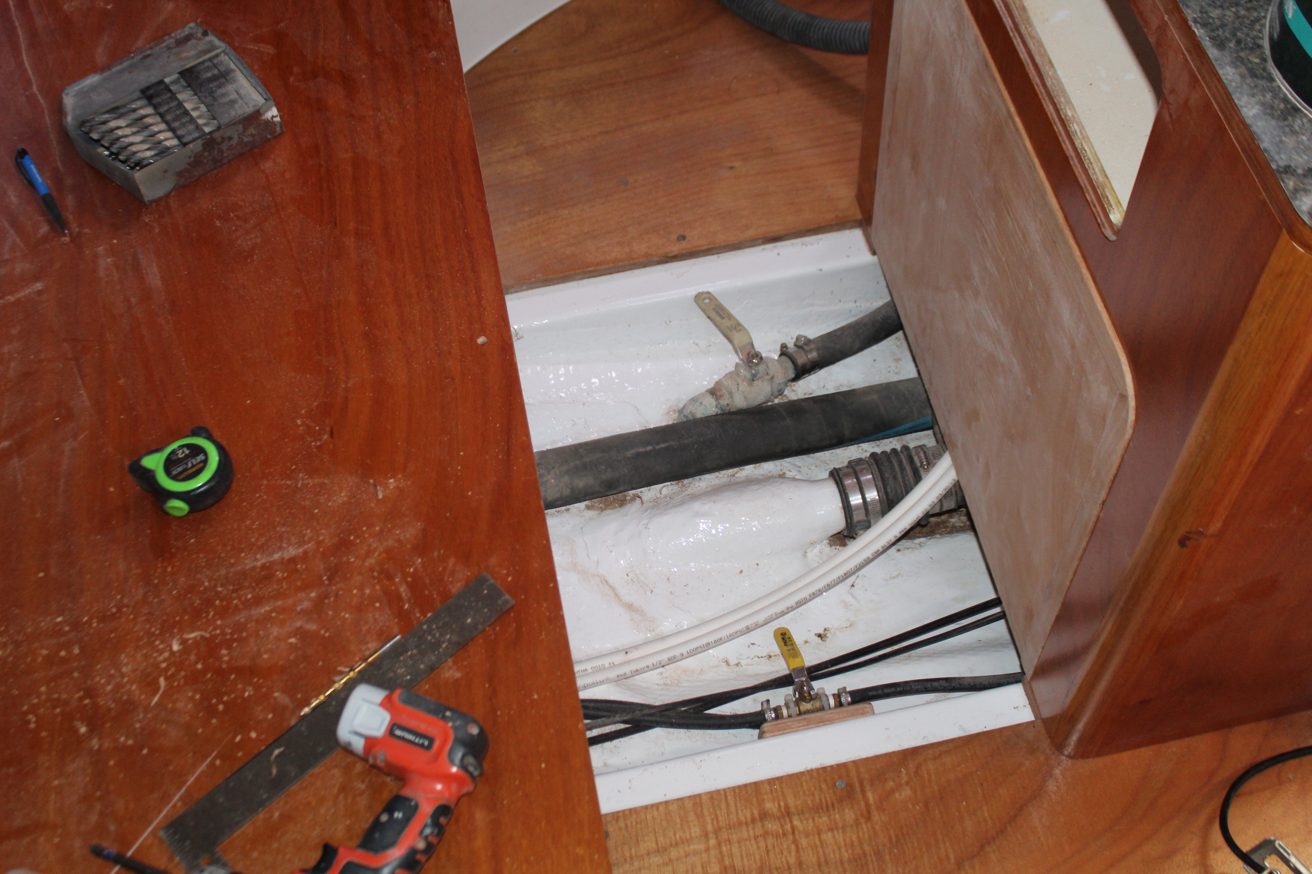
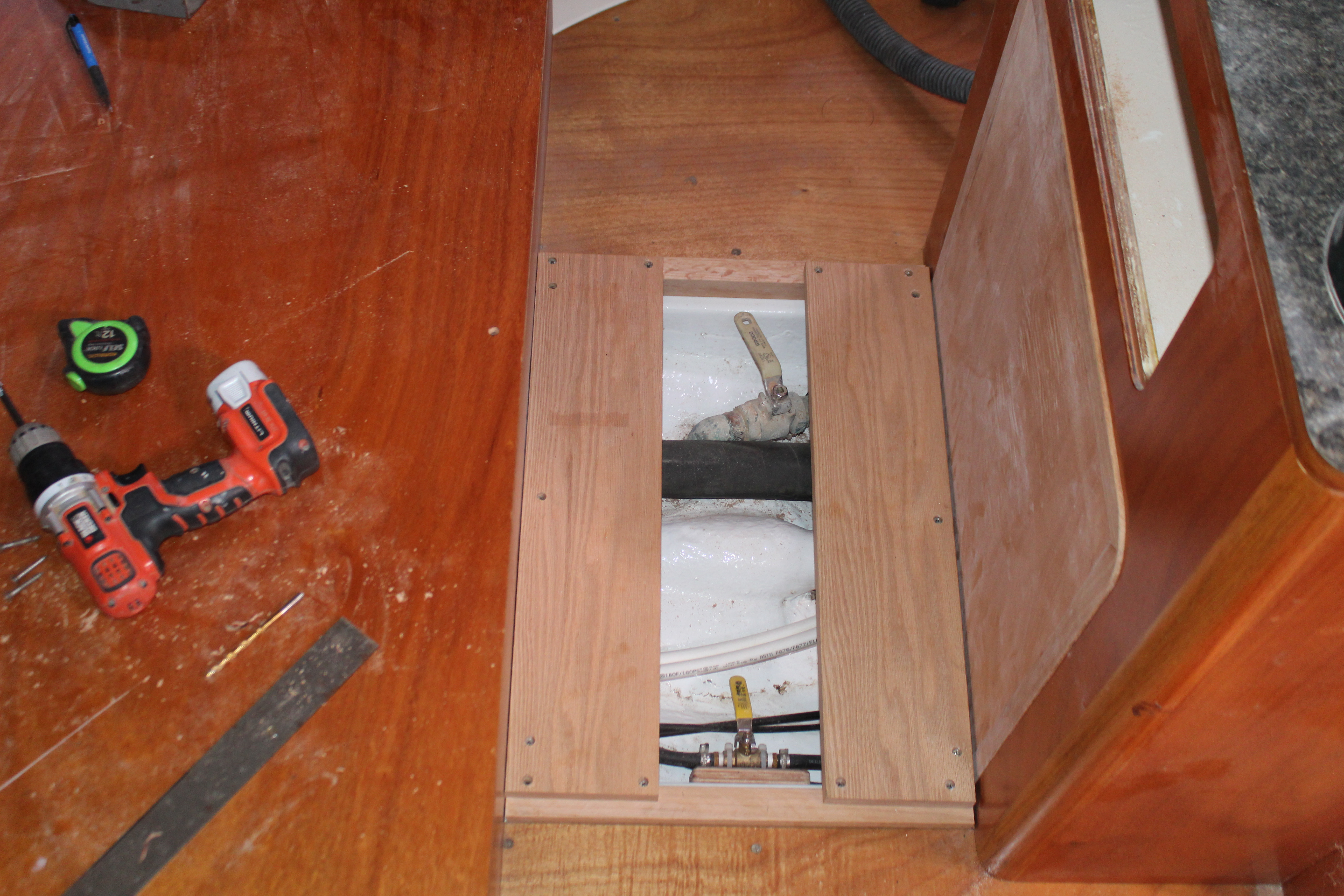
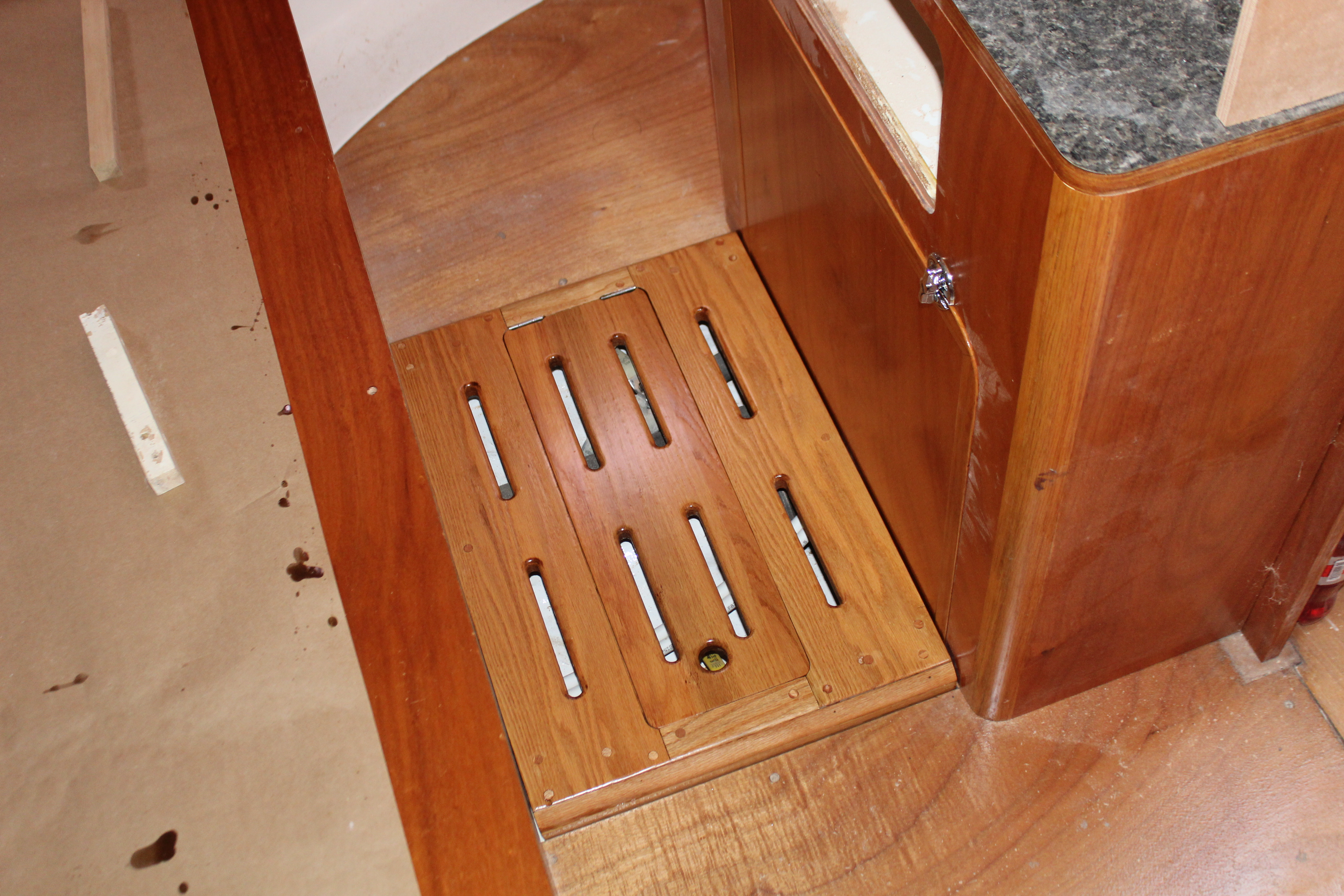
I have been stepping over this gap in the aft cabin for several years - time to make it whole again. Originally the factory had a teak grate over this area that fit flush with the floor. Problems started years ago when I replaced the original engine raw water intake gate valve with a proper seacock - the handle for the new seacock protruded above the old grate. I knew that anything I put there would have to be elevated for clearance. A little measuring gave me the new height - I needed about an inch to clear the valve with the handle in place. Luckily I have quite a bit of extra 1 1/4" square red oak so that will become the base for the new grate:
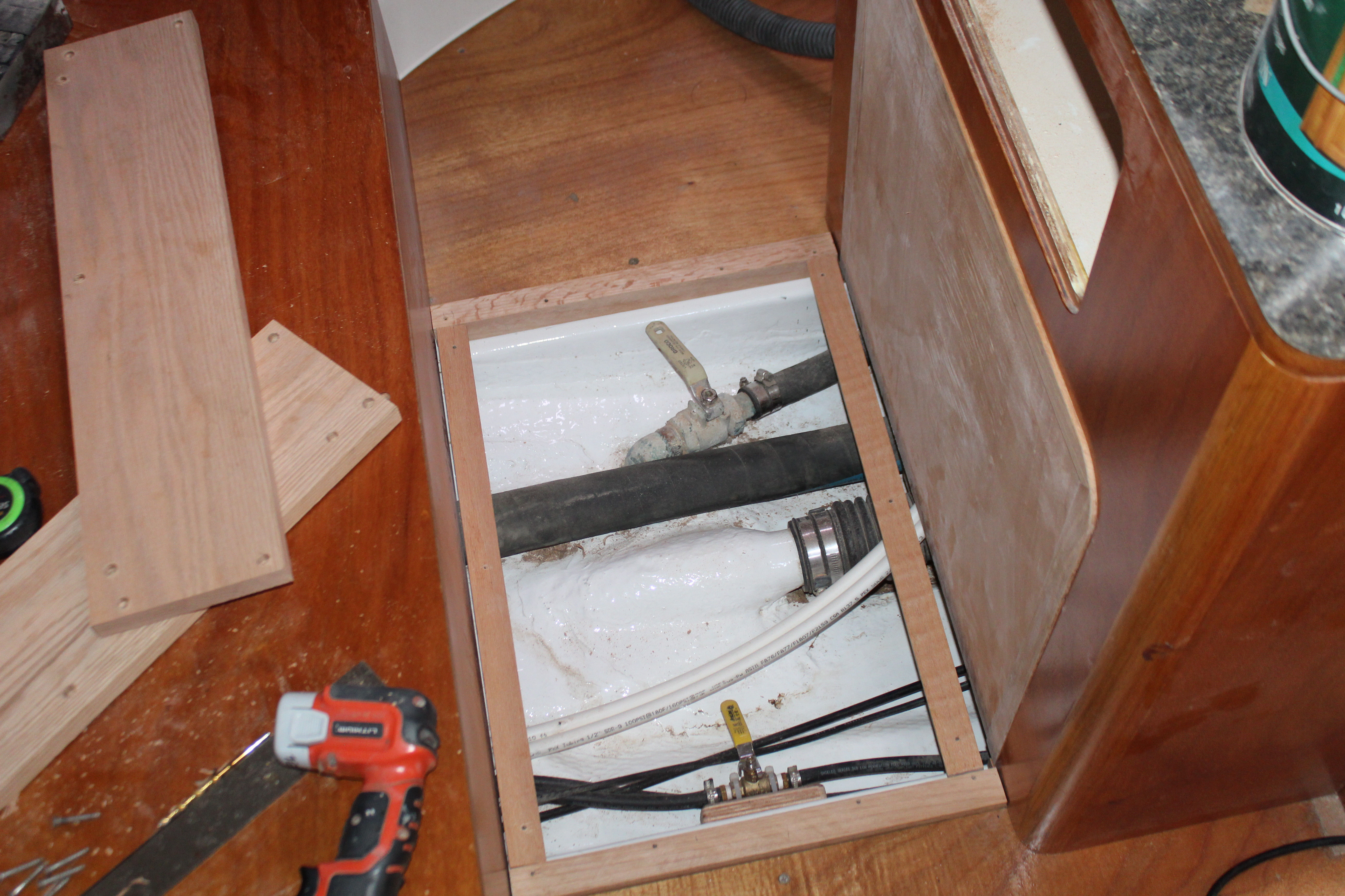
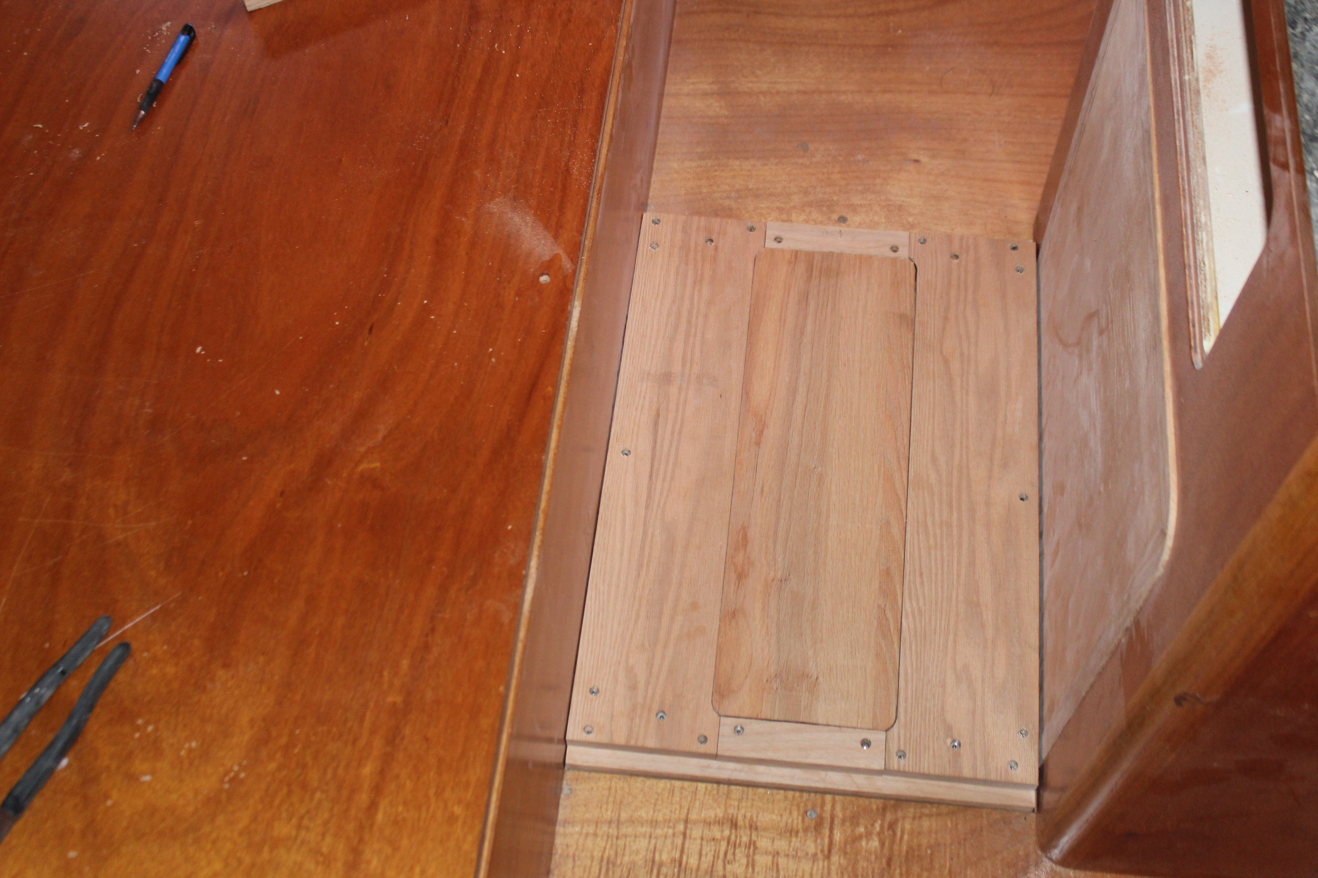
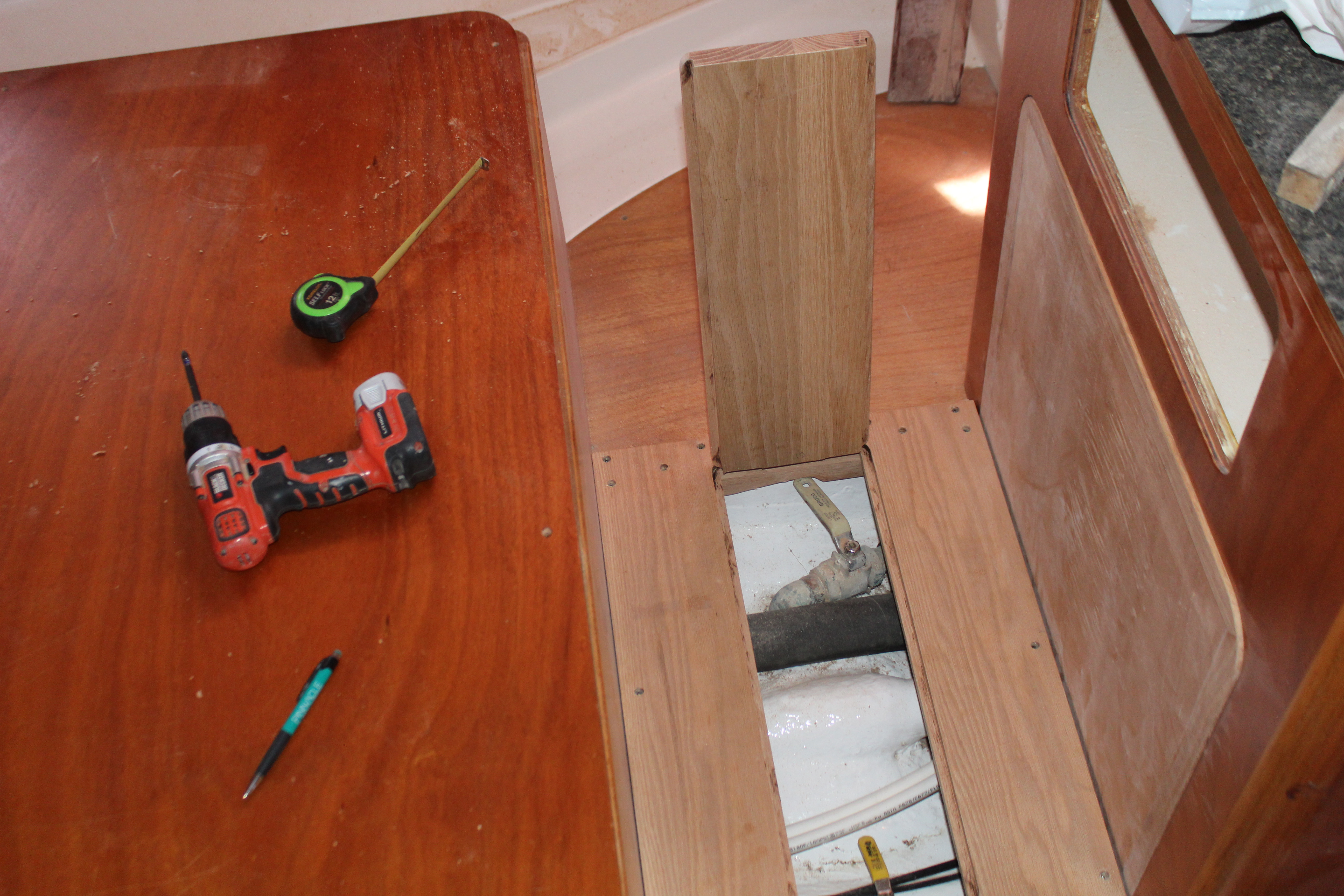
The old grate could be pulled out but it left the entire space open - I decided there was no need for that since most of the time all I need access to is the fuel cutoff and raw water valves, so I will have a hinged center section for easy access:
A little time with the router on the edges of the center section makes a very solid platform:
Next up, finishing.
Cheers,
Mark
The next big project reveal will be soon - but in the meantime I have a thousand (and one!) little projects that I use to fill time and keep motivated. Here's one:
I have been stepping over this gap in the aft cabin for several years - time to make it whole again. Originally the factory had a teak grate over this area that fit flush with the floor. Problems started years ago when I replaced the original engine raw water intake gate valve with a proper seacock - the handle for the new seacock protruded above the old grate. I knew that anything I put there would have to be elevated for clearance. A little measuring gave me the new height - I needed about an inch to clear the valve with the handle in place. Luckily I have quite a bit of extra 1 1/4" square red oak so that will become the base for the new grate:
The old grate could be pulled out but it left the entire space open - I decided there was no need for that since most of the time all I need access to is the fuel cutoff and raw water valves, so I will have a hinged center section for easy access:
A little time with the router on the edges of the center section makes a very solid platform:
Next up, finishing.
Cheers,
Mark
Side project Part 2:
Before putting any finish on the platform I needed to complete it with hinges and a latch:
And some ventilation:
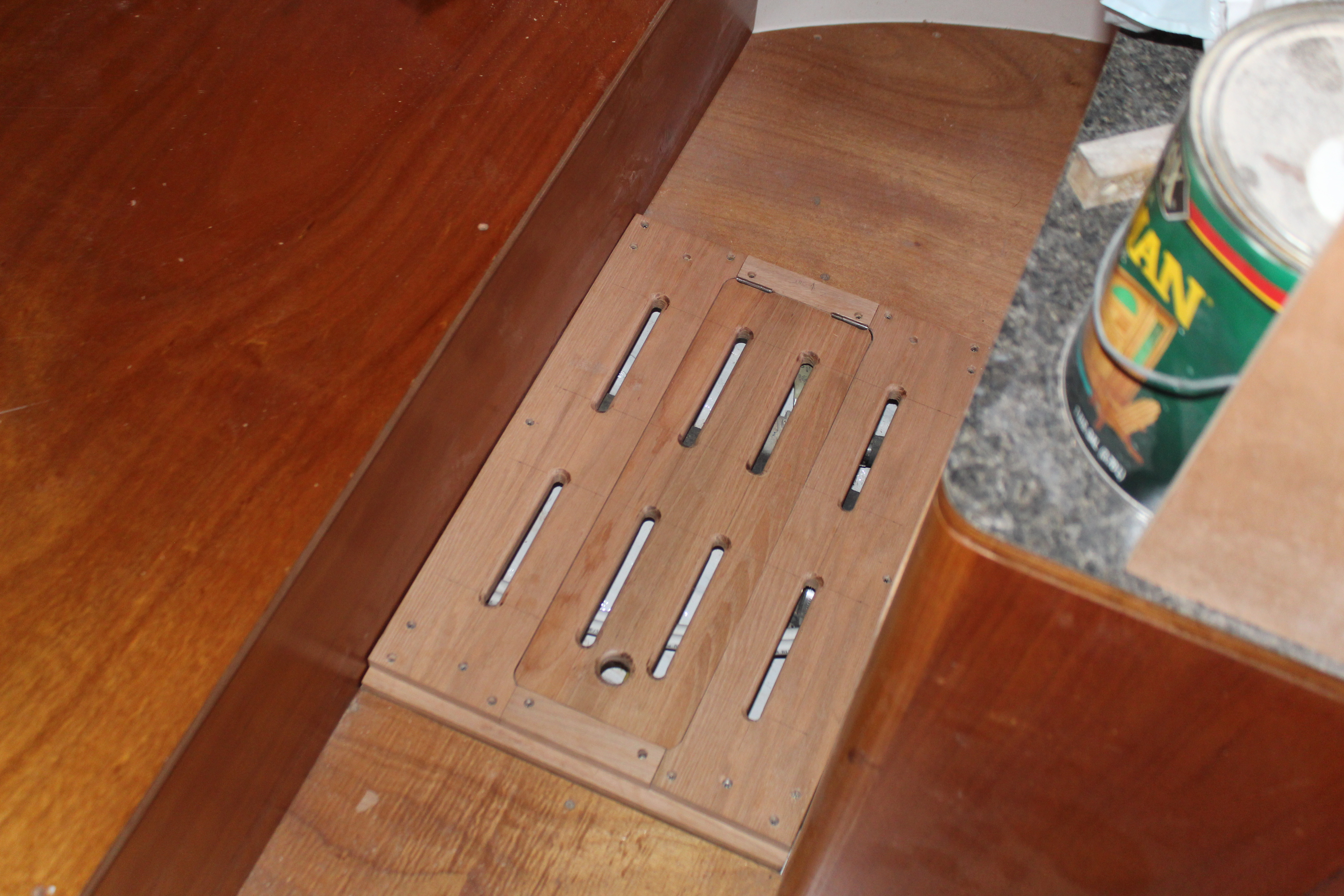
The vents are there for (I presume) engine intake air (the old grate had vents also). I cut some slots and finished the edges with a roundover bit. Now it's time to take it all apart! First up is some thickened epoxy for all the undersides and the base was reassembled. Now I can start adding clear urethane:
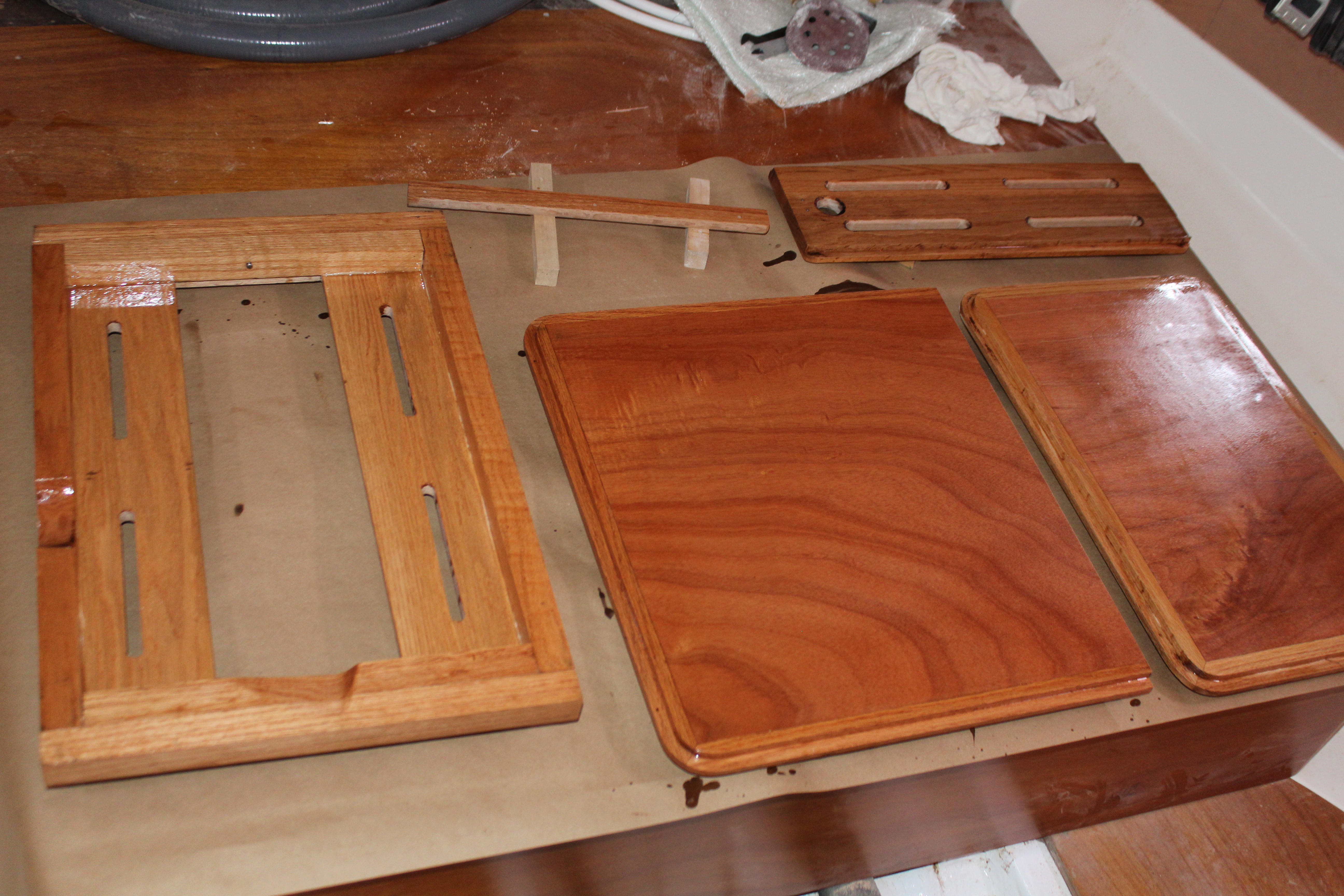
I had some other engine access panels to do at the same time. Four coats later and it's together!
I had to guess (semi-educated) at the actual floor height since the final flooring has not been determined yet, so the side chamfer allows for that. The entire platform can be removed if necessary but it's nice to just be able flip the center up quick and easy to get to the fuel and raw water.
Next up, the next big project!
Cheers,
Mark
Before putting any finish on the platform I needed to complete it with hinges and a latch:
And some ventilation:
The vents are there for (I presume
) engine intake air (the old grate had vents also). I cut some slots and finished the edges with a roundover bit. Now it's time to take it all apart! First up is some thickened epoxy for all the undersides and the base was reassembled. Now I can start adding clear urethane:
I had some other engine access panels to do at the same time. Four coats later and it's together!
I had to guess (semi-educated
) at the actual floor height since the final flooring has not been determined yet, so the side chamfer allows for that. The entire platform can be removed if necessary but it's nice to just be able flip the center up quick and easy to get to the fuel and raw water.Next up, the next big project!
Cheers,
Mark
I wasn't getting it until the picture with the slots cut in it. That is pretty nice work.
I do have a question however. Why thickened epoxy for the undersides? When I made new floors I just used neat epoxy.
Thanks! I should have clarified - the thickened epoxy was to glue all the various components together in addition to screwing, to prevent moisture from eventually seeping through all the seams. After reassembly and the epoxy drying I sealed the undersides with urethane which should protect the wood as well as epoxy.
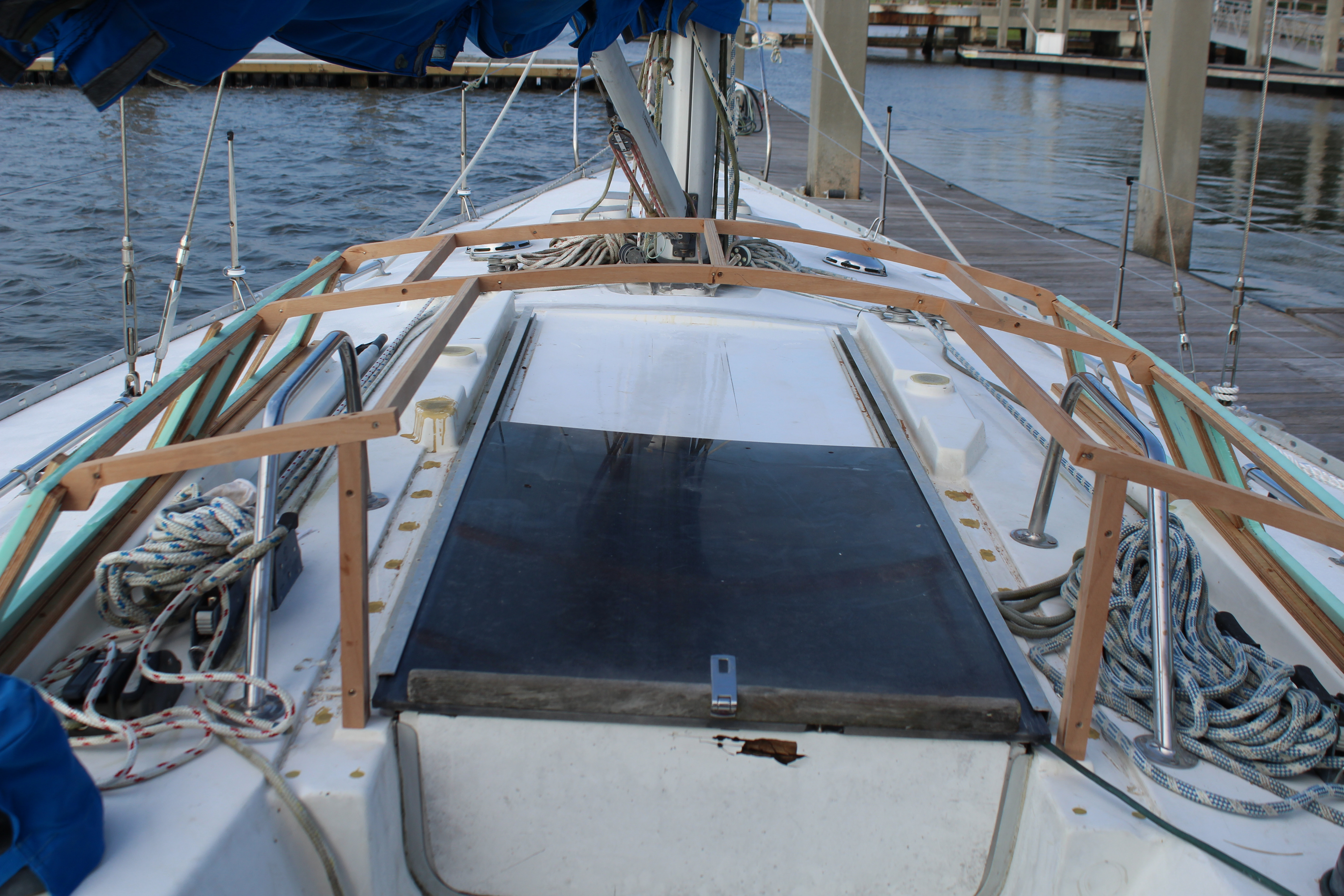
The next big project - the deck enclosure/hard dodger:
As I have (I think) stated before, Hunter dropped the ball with the hatch setup and entryway on these boats (my opinion, of course!). The factory setup is an acrylic hatch set in extruded aluminum channels set under a molded cover. Problem is, the cover is so big and heavy that cleaning underneath is a major undertaking, and there are enough openings around the cover that dirt, debris and water can easily enter and build up in the aluminum channels. This allows water to dam up under the cover and leak around the hatch to the interior. It also doesn't help that the acrylic hatch is big and heavy enough that over time it has developed a sag which allows water to pool on the hatch itself. I have pulled the cover multiple times to clean under it and the original cover really took a beating.
Problem 2 is access through the entryway. The placement of the traveler necessitates a high bridge deck just prior to the entryway. Not a problem - in fact I kinda like it that way - until I tried putting up the dodger. This created such a small area at the companionway that the only way to enter was to crawl into the boat!
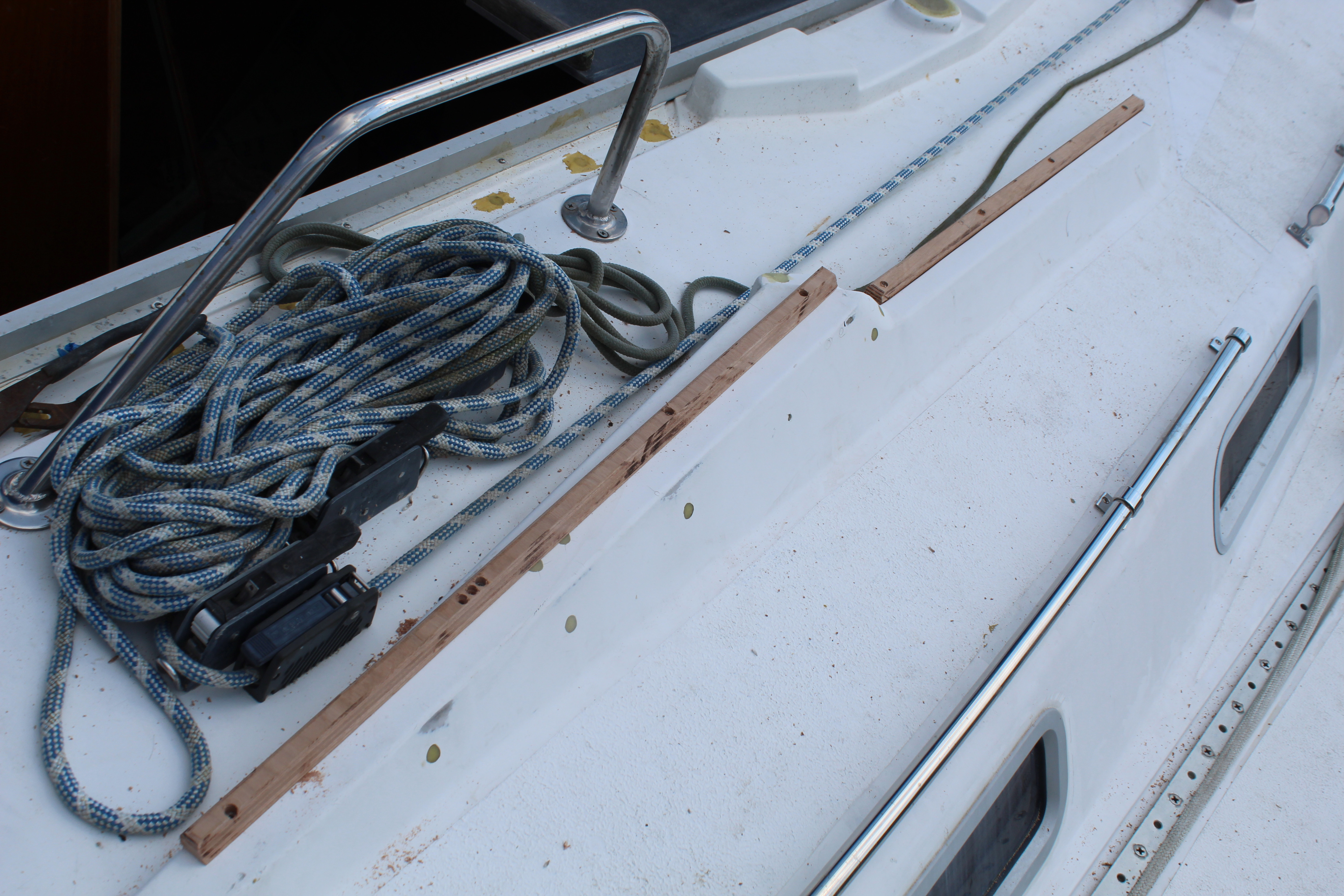
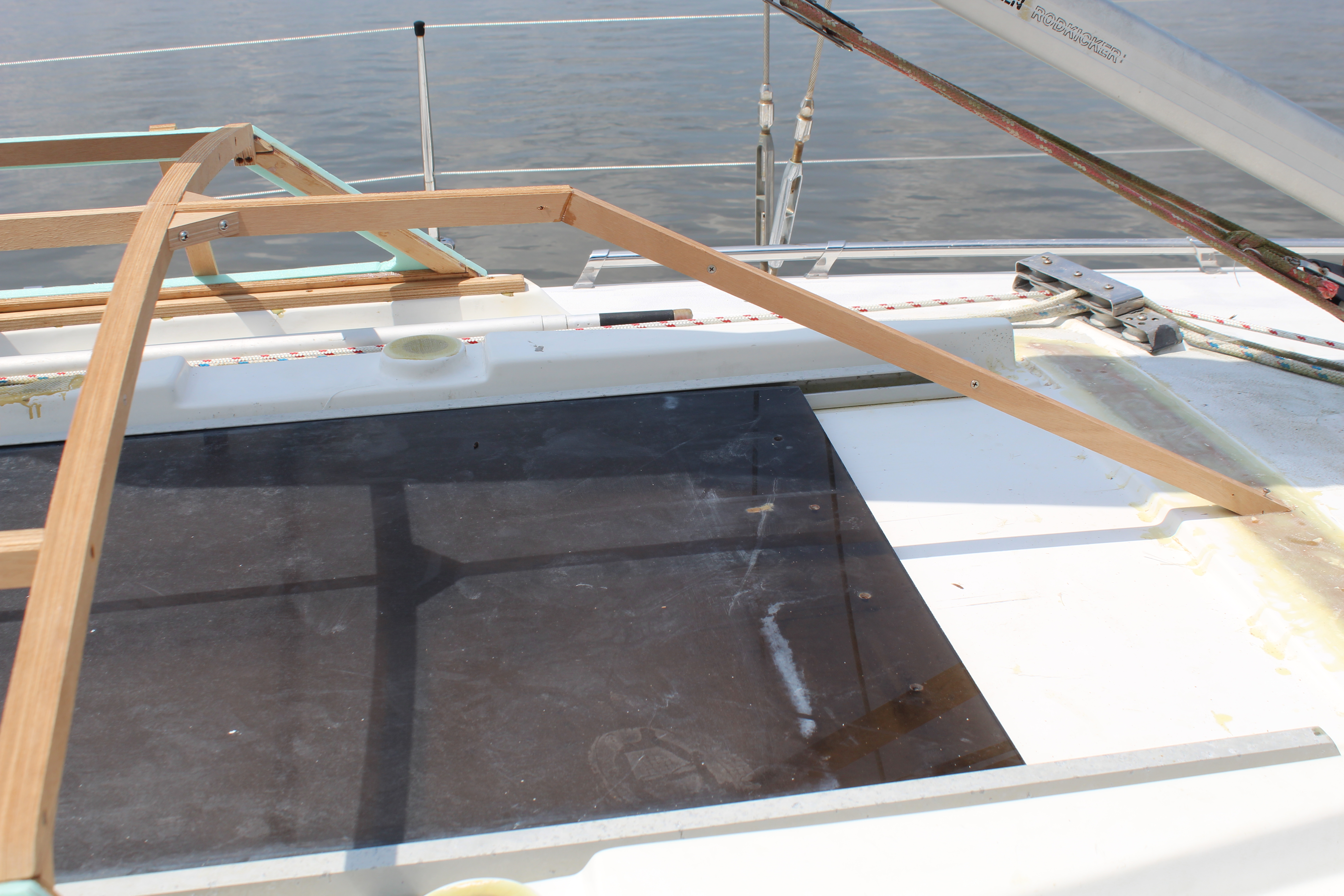
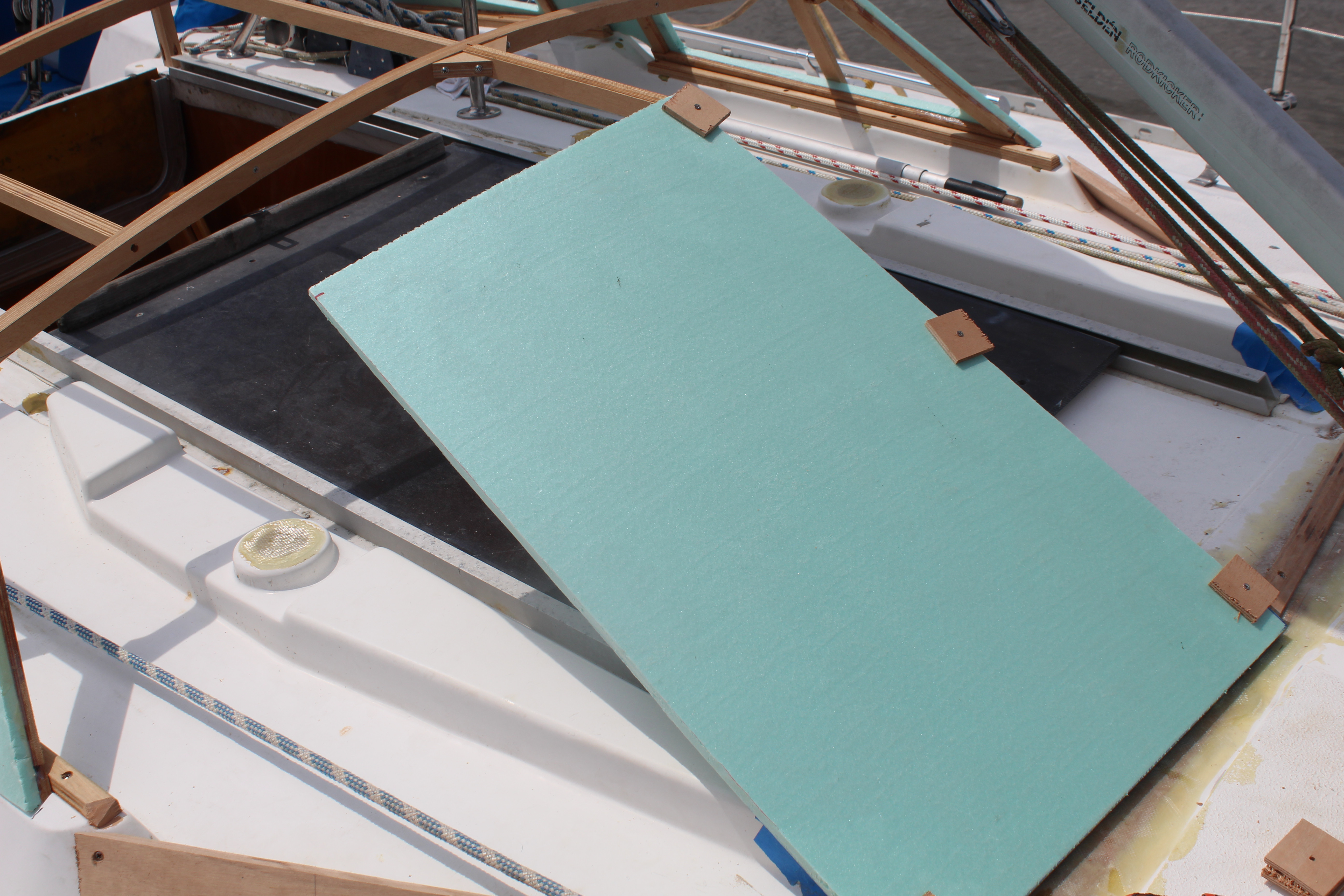
So - time to kill 2 birds with one stone. I have been brainstorming a hard dodger that more closely resembles a deck enclosure like you'd see on a Deck Salon. First up was measuring and cutting some XPS foam for the side panels to determine the overall height:
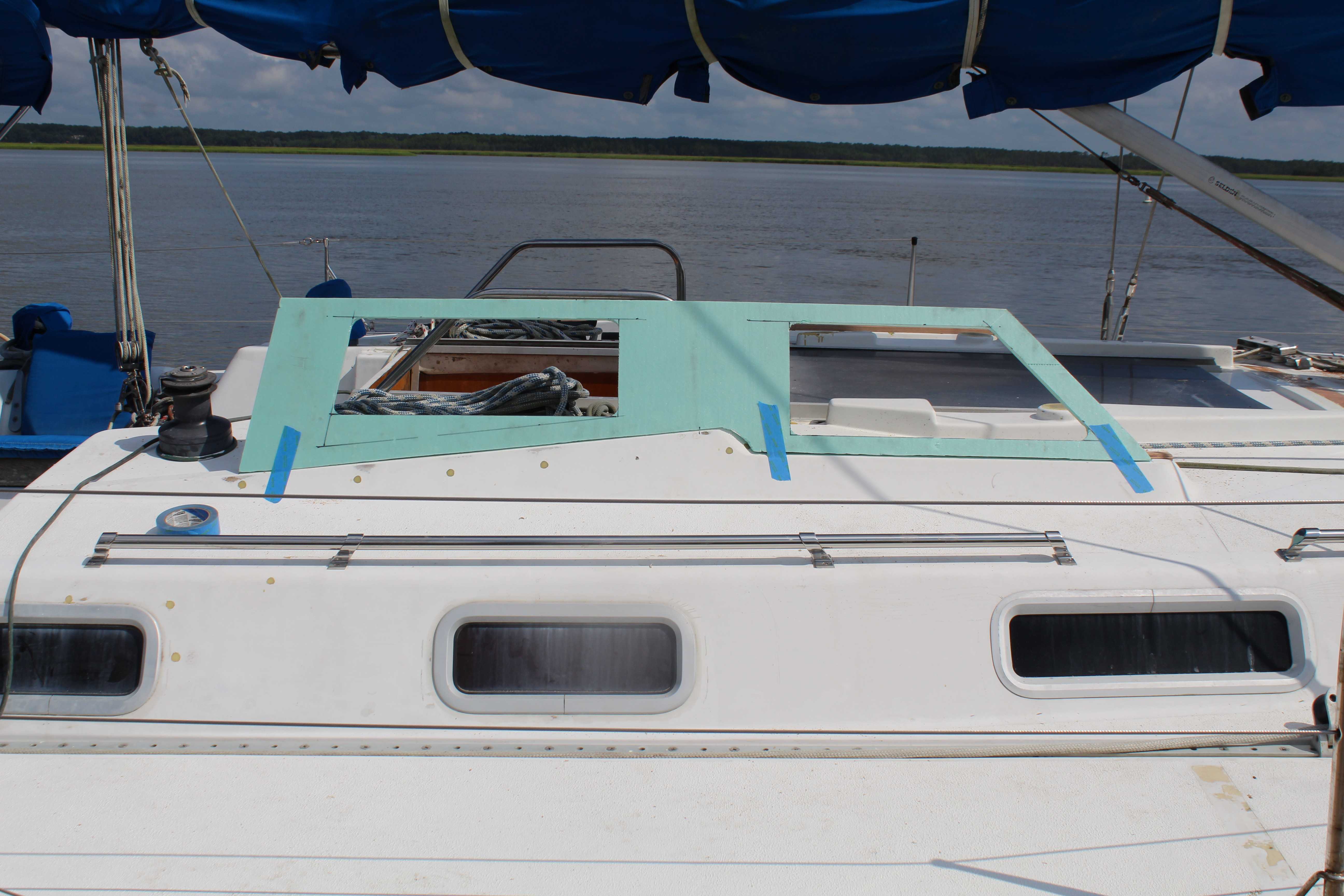
These were cut and taped in place, then using the TLAR method, take 20 (or more) steps back to eyeball things until it looks right. Then use the first side to pattern the opposite side. Next is some internal bracing:
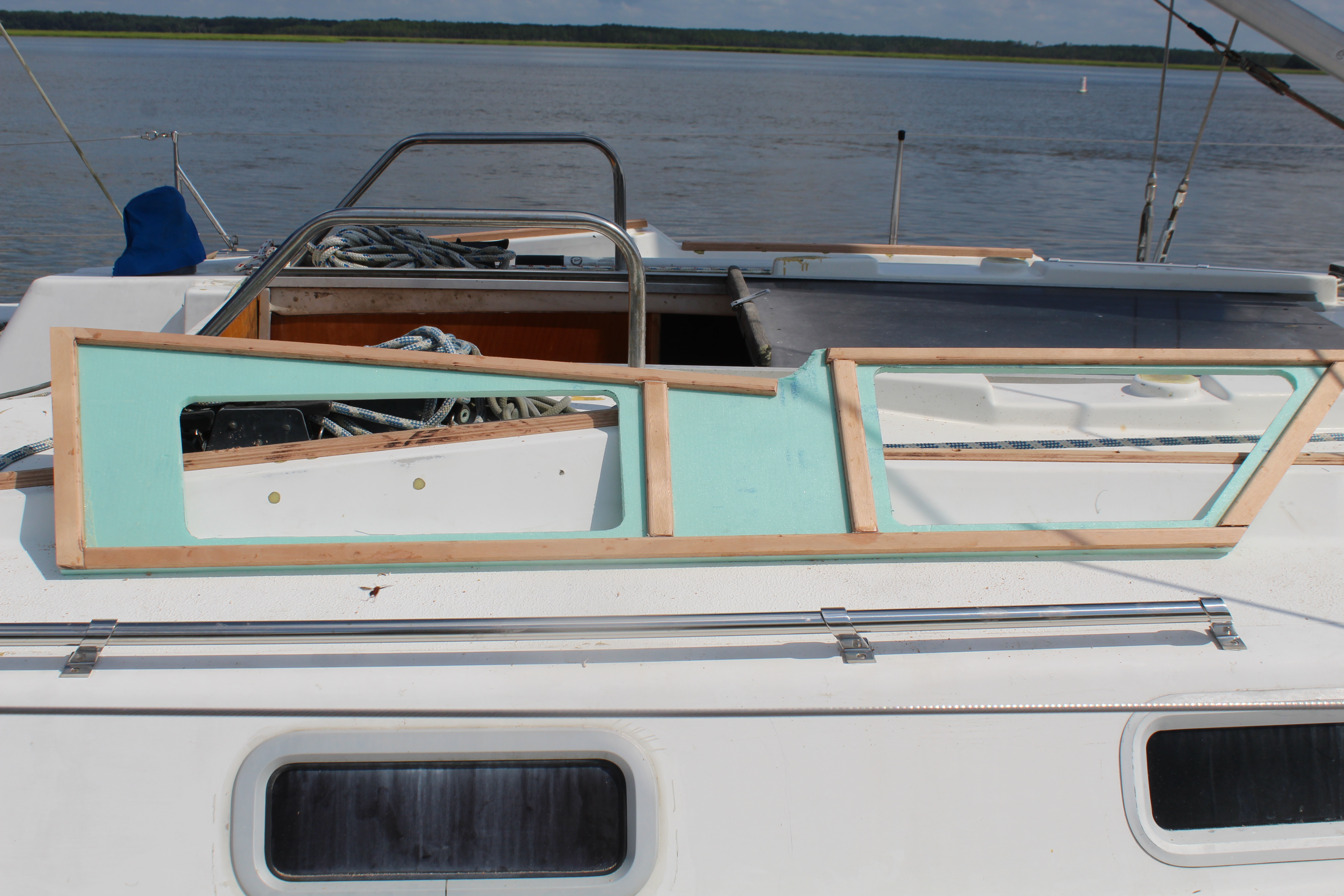
Bracing cut to accommodate the angle the sides will sit at then epoxied to the foam. I then needed some braces to locate and secure the sides to the boat. They are mounted to the original moldings for the original hatch cover:
Sides measured, mounted and braced to the cabin top. Next up, measuring and making the crown bracing for the top. Stay tuned!
Cheers,
Mark
As I have (I think) stated before, Hunter dropped the ball with the hatch setup and entryway on these boats (my opinion, of course!). The factory setup is an acrylic hatch set in extruded aluminum channels set under a molded cover. Problem is, the cover is so big and heavy that cleaning underneath is a major undertaking, and there are enough openings around the cover that dirt, debris and water can easily enter and build up in the aluminum channels. This allows water to dam up under the cover and leak around the hatch to the interior. It also doesn't help that the acrylic hatch is big and heavy enough that over time it has developed a sag which allows water to pool on the hatch itself. I have pulled the cover multiple times to clean under it and the original cover really took a beating.
Problem 2 is access through the entryway. The placement of the traveler necessitates a high bridge deck just prior to the entryway. Not a problem - in fact I kinda like it that way - until I tried putting up the dodger. This created such a small area at the companionway that the only way to enter was to crawl into the boat!
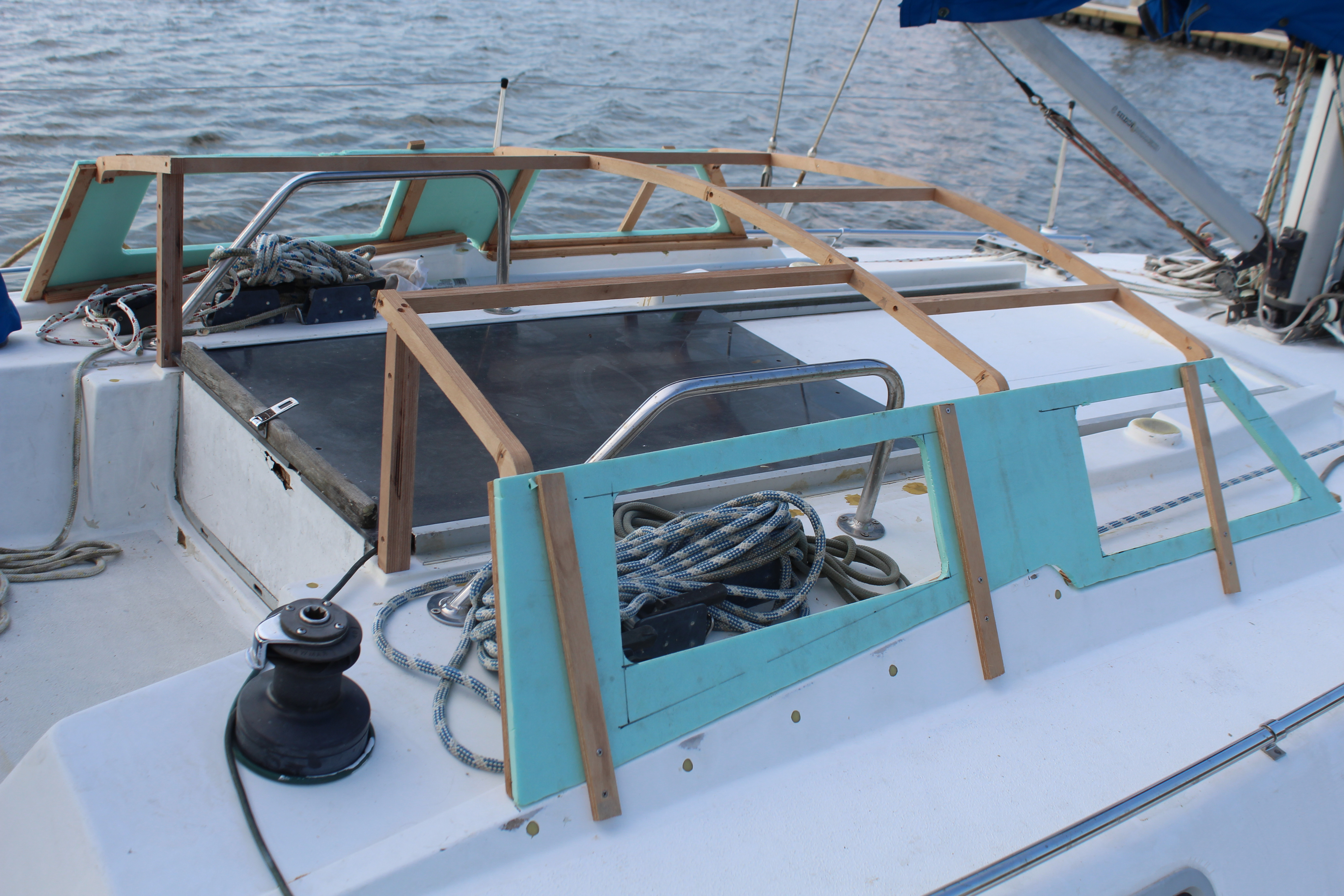
So - time to kill 2 birds with one stone. I have been brainstorming a hard dodger that more closely resembles a deck enclosure like you'd see on a Deck Salon. First up was measuring and cutting some XPS foam for the side panels to determine the overall height:
These were cut and taped in place, then using the TLAR method, take 20 (or more) steps back to eyeball things until it looks right. Then use the first side to pattern the opposite side. Next is some internal bracing:
Bracing cut to accommodate the angle the sides will sit at then epoxied to the foam. I then needed some braces to locate and secure the sides to the boat. They are mounted to the original moldings for the original hatch cover:
Sides measured, mounted and braced to the cabin top. Next up, measuring and making the crown bracing for the top. Stay tuned!
Cheers,
Mark
Deck enclosure/hard dodger, Part 2:
With the sides ready it's time to mount them and start on the bracing for the top. I tried to mimic the arc the cabin top has, or at least complement it. Again started with the TLAR method for initial measurements then I transferred those measurements to some ply:
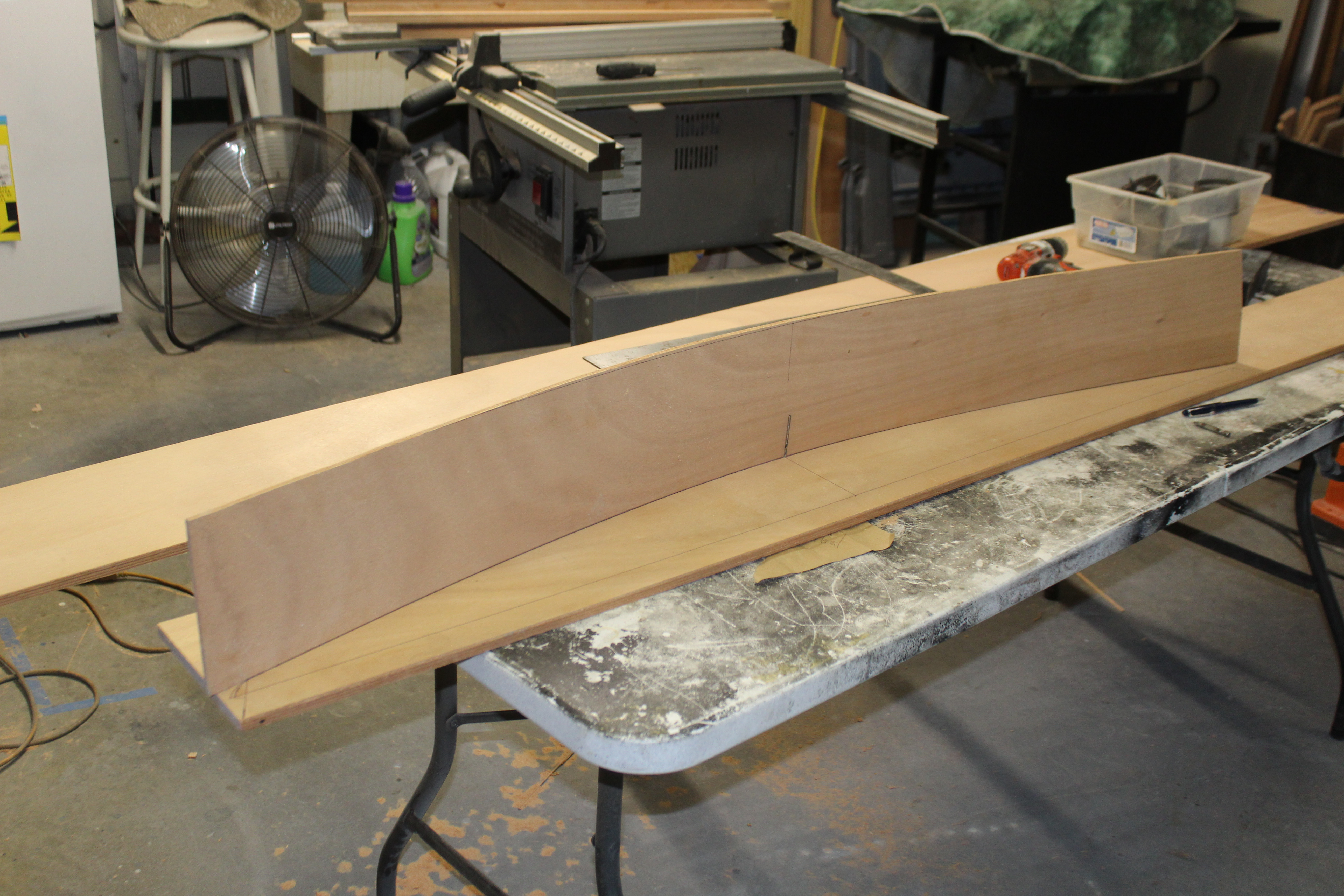
I used some spare 1/4" and anchored it with drill bits to recreate the arc. The bows are cut from 1/2" ply, doubled to make 1x1 pieces so 6 total to make 3 bows. Next up was to mount the sides in place and secure, then locate and secure the bows and add some bracing:
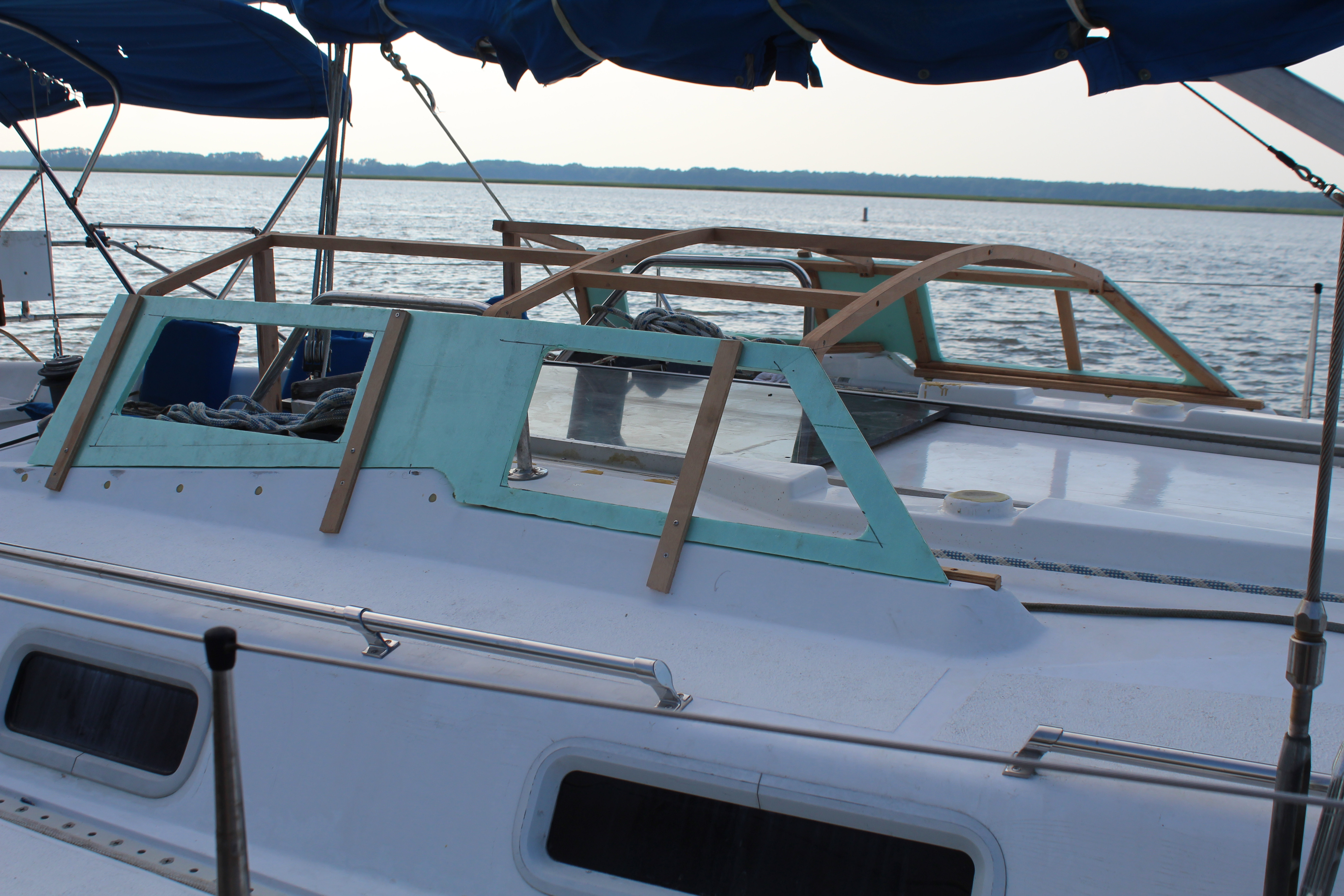
I cut and braced the rear bow for cabin access. Still refining this area.
Next up, filling divots, grooves and holes.
Cheers,
Mark
With the sides ready it's time to mount them and start on the bracing for the top. I tried to mimic the arc the cabin top has, or at least complement it. Again started with the TLAR method for initial measurements then I transferred those measurements to some ply:
I used some spare 1/4" and anchored it with drill bits to recreate the arc. The bows are cut from 1/2" ply, doubled to make 1x1 pieces so 6 total to make 3 bows. Next up was to mount the sides in place and secure, then locate and secure the bows and add some bracing:
I cut and braced the rear bow for cabin access. Still refining this area.
Next up, filling divots, grooves and holes.
Cheers,
Mark
Deck enclosure/hard dodger. Part 3:
With the sides and top framework set, it's time to work on the front. Before I can start framing that up, though, I have to do something about this:
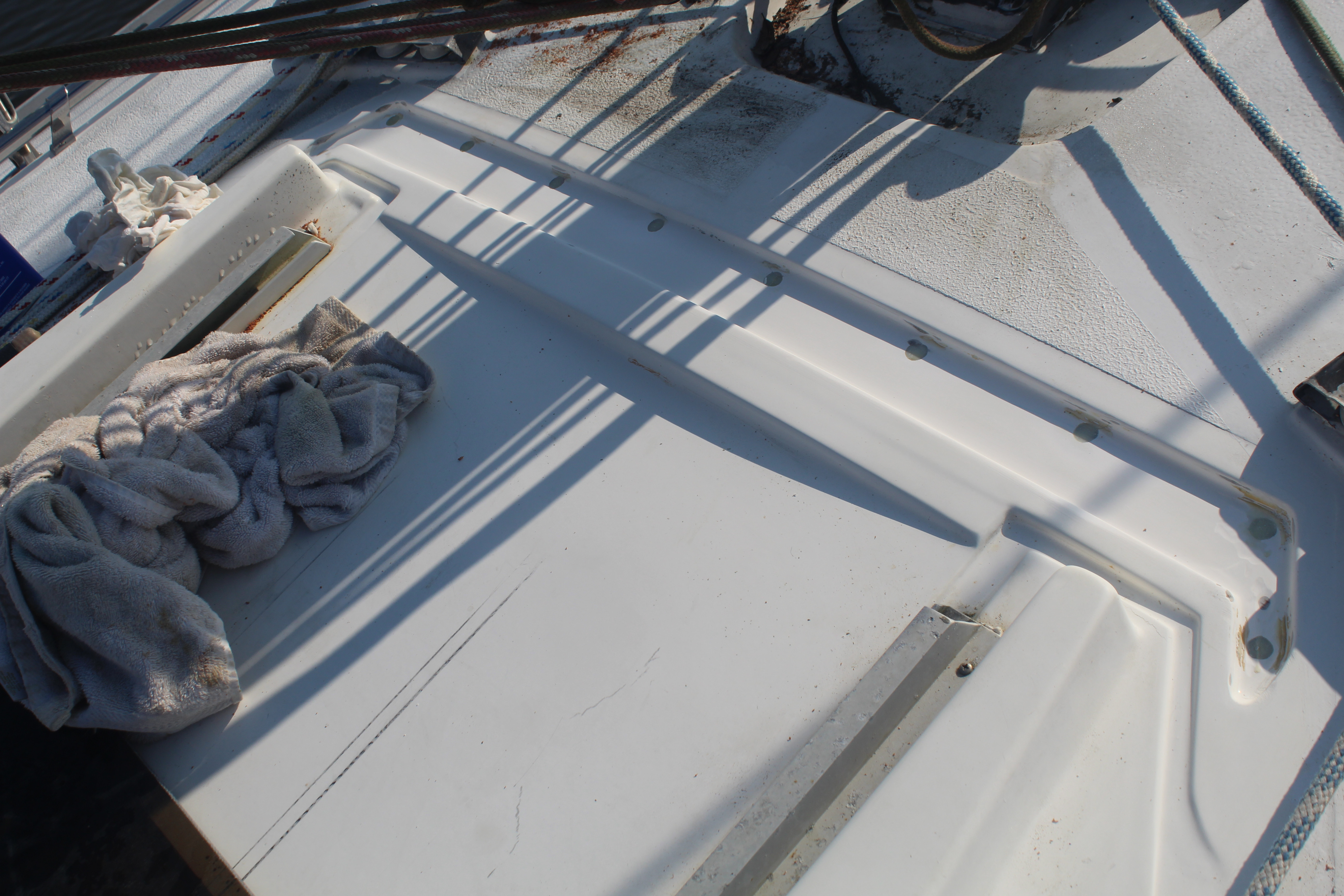
This channel was molded into the deck to fit the front of the old hatch cover and it does not work for my plan, so it got filled:
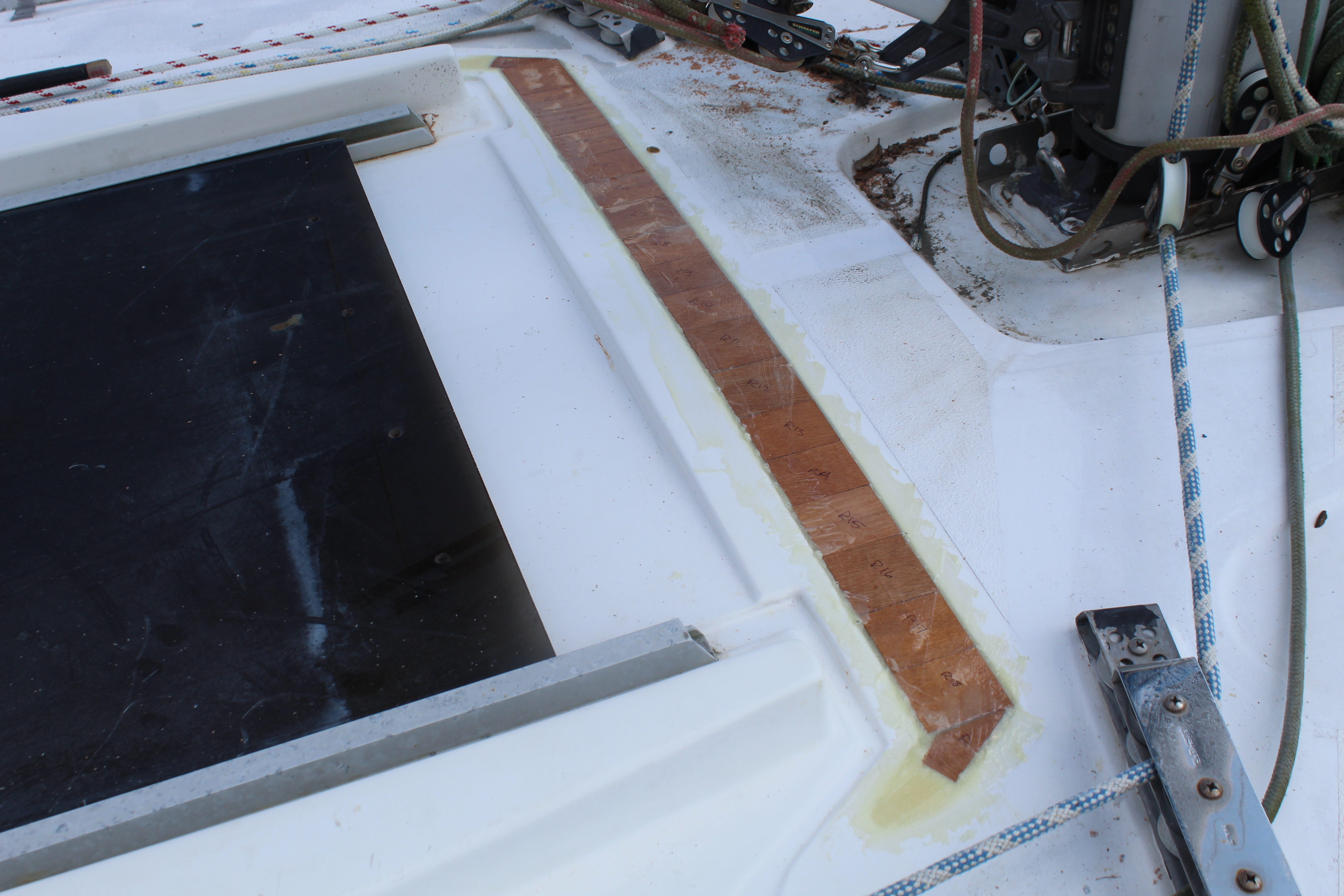
After that dried, I sanded everything flush and added 2 layers of 1708 to seal it up. Next, again using the TLAR method, I roughed out the front center frame:
I wanted this to follow the angle of the boom vang (for symmetry, you know). Lots of standing back and checking before it looked right. I then added the lower front panel support to the deck and cut out a template for the front panel:
The front panels will set at a slight angle off perpendicular so this panel will determine the positioning of it's support brace.
Next up, finishing the forward framing.
Cheers,
Mark
With the sides and top framework set, it's time to work on the front. Before I can start framing that up, though, I have to do something about this:
This channel was molded into the deck to fit the front of the old hatch cover and it does not work for my plan, so it got filled:
After that dried, I sanded everything flush and added 2 layers of 1708 to seal it up. Next, again using the TLAR method, I roughed out the front center frame:
I wanted this to follow the angle of the boom vang (for symmetry, you know
). Lots of standing back and checking before it looked right. I then added the lower front panel support to the deck and cut out a template for the front panel:
The front panels will set at a slight angle off perpendicular so this panel will determine the positioning of it's support brace.
Next up, finishing the forward framing.
Cheers,
Mark