Old Boat - Old wiring - old batteries

Oct 22, 2014
21,104
CAL 35 Cruiser #21 moored EVERETT WA
Wanting to get through to winter when I plan to do complete electrical refit.
Here is my present situation. I went sailing last weekend and batteries died after radio use and powering my laptop (Laptop DC charger states up to 10amp charger - perhaps this was the issue). Batteries are "Econo Start" batteries (no idea of manufacturer) dated 2011 so not surprised that they are not able to hold much charge and supply 5 to 6 hours of power.At end of sail could not start engine.

Looking for clarification on what Previous Owner did with the wiring, am I reading this electrical layout correctly.

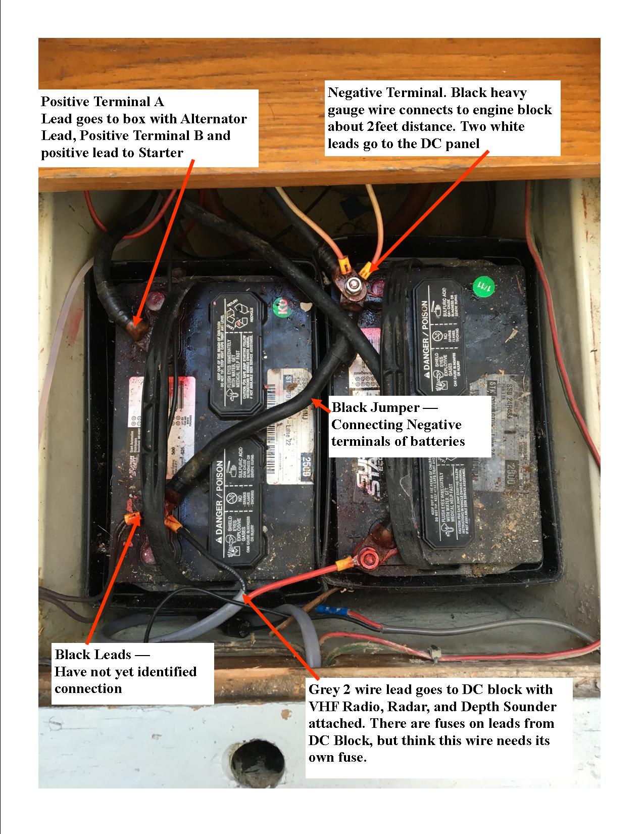
Looks to me that the batteries are hooked up parallel. Two positive leads are attached going to what appears is an echo device (no product name but has has the 2 Positive DC leads attached, one lead then going to the engine starter and a lead coming off the alternator).
One negative battery lead is attached to the transmission/engine block.
There is a jumper lead going between the two negative terminals of the batteries.

There is a grey wire with Red and Black 12AWG leads that go to a DC power block with the VHF radio, Depth Sounder, and Radar attached. These Equipment Units are fused at this block.
Concern is that there should be a fuse at the battery side of this grey lead, not sure at what amp level. Length of run to block is 8 feet.
I want to attach a DC lead to power my Wallas Furnace 40DT. It sits 16 feet from the battery. Thought is I should attache to battery and not the DC block. The heater is using 12 AWG black and red leads with ring connectors. Which battery terminals would be best to use?

Currently we use Marina's at night where I can attach the boats battery charger (it is an auto battery charger) to recharge for next day's sail.

Future plan is to install Sterling 40 AMP Pro Charger (from Compass Marine - just received - thanks) and an ARC unit using a couple of Golf Cart 6 Volt batteries in series. This is the winter project I identified. Need to get to that time and not burn up boat electrical system.
Your help is most appreciated.
John
1974 Battery Connections CAL35C.jpg
 

SFS

.
Aug 18, 2015
2,070
Currently Boatless Okinawa
Wow, batteries "facing" the same direction (lugs on left side, cell openings to right of centerline), but the positive and negative lugs are on different ends of each battery. You always have to pay attention.

Sorry that I can't help you with your question. Perhaps MaineSail will weigh in, since you bought a piece of gear from him.
 
Oct 22, 2014
21,104
CAL 35 Cruiser #21 moored EVERETT WA
Thanks hope so. Like his work on this site.
Old boat, old batteries and old ideas of wiring. Did not post a picture of the wiring as I did not want to frighten anyone.
 
May 20, 2016
3,014
Catalina 36 MK1 94 Everett, WA
I believe you need fuses within 6" of the battery
You need to wrap that upper left cable with red tape at least 6-8" back.
I would put a fusible link (AMG/ANL) directly off the positive terminal.
That wire up to the distribution buss looks way way to small (depending on the vintage of your Radar) (12 gauge??)

- I don't see how your house batteries are being charged. From your written description I thought maybe the "echo" box was a ACR - but the picture doesn't agree (unless it is being back feed from your DC junction block ?? scary)

When you say A & B terminal - is that like on a A, B, Both, OFF switch ??

Your (our) vintage of boat would have been wired with the big A,B,both, off switches - everything would then be feed to the motor off the common lug on that switch -- all of your House loads would typically be connected to B. A updated solution is to charge the house battery using a ACR (automatic combining relay iirc) you would start the boat on A unless it goes dead - then you would use B or both to start the boat.

I have a wire tracer if you would like to borrow it.
 
Feb 26, 2004
22,776
Catalina 34 224 Maple Bay, BC, Canada
Those batteries look like toast. If they look that bad, get rid of them and decide how you want to set up your electrical system: 12V, 6V, ACR or combiner or echo charger, etc.

Without explaining how you use your boat, no one can possibly tell you what to do. If you're a marina hopper, then 2 Grp 31s should do just fine. I have 3 Grp 31s for a 390 ah house bank, with a separate 60 ah reserve bank battery, 1-2-B switch, AO to the house bank with a combiner, 100A alternator with a Balmar MC-612 external regulator. Couldn't be happier. I anchor out a lot.

Don't know if you've ever seen this:

http://c34.org/bbs/index.php/topic,5977.0.html
 
Feb 26, 2004
22,776
Catalina 34 224 Maple Bay, BC, Canada
if so that would charge your house battery - but how is it connected -- also it limits you to charging the house battery at only 15A - so it will take a while before it recovers.
That's NOT how it works. You charge your HOUSE bank and the echo feeds the reserve bank.
 
Sep 8, 2014
2,551
Catalina 22 Swing Keel San Diego
I'm still looking for the emoticon called 'face palm'....
Yeah, you have a big mess there... So yes, you need to pretty much tear out that whole system and start over.
First off... Any battery that has the word 'start' in it is a starting battery, not a deep cycle battery for house bank use. The reason your battery bank is failing is because it is being used to start the engine, and then continues to feed your domestic 12V power need. Start batteries are not designed to be deep cycled (fully discharged before recharging)... So you only need one start battery that is hooked only to the engine for starting purposes, your house battery (or batteries, as many as you feel you will need) are separate.
In most cases, a pair of group 27 Deep Cycles should satisfy all your 12V power needs in a boat your size. Hopefully you have another location to secure a box for a group 24 starting battery you can dedicate to engine starting. Yes, everything should be fused properly as well. To correct myself, by saying 'tear everything out' I don't necessarily mean all the wring too. if it is proper tinned marine grade wire it can stay, just needs to be hooked up correctly and from the looks of it terminated correctly as well. I let Main Sail and others take over from here... Its a big job, but it can be done relatively easily if you take it one step at a time.
 
  • Like
Likes: jssailem
Mar 20, 2012
3,983
Cal 34-III, MacGregor 25 Salem, Oregon
John, as you have guessed, the picture shows a botched or "make do" install. the battery to the right will be the dominant battery because of how we see the batt cables ran
going forward, what type, size and quantity of batts you choose really depends on your power needs, but if space does not allow for enough 6v gc batts, I would go with the trojan 12v true deep cycle batts, which in my opinion are as good. expensive but worth it... and a bit simpler install.

fusing should be sized according to the wire size it is protecting, and near the source where the wire will get its power from, which in this case is the batteries.... if a large wire runs from a battery to a buss bar, where smaller wires will be connected to power "smaller" circuits, the large wire needs to be fused near its source, and after the buss connections, the smaller wires need fuses installed as well, because the source of their power is from the high amperage buss bar.... every step down in wire size needs a step down in fusing to protect the wire from melt down in the event of a short.... and parallel batteries should always be connected as per the diagram shown...
parallel connection.jpg
 
Oct 22, 2014
21,104
CAL 35 Cruiser #21 moored EVERETT WA
I'll take a photo of the wiring what I'm calling an "echo" unit Sunday and post it.
Yes I agree the batteries are toast. I replaced them Wednesday with a couple of 12 volt group 24 "labeled - Costco Deep/Cycle Marine" batteries as a stop gap to get through this sailing season.

My intention is to be able to sail and anchor out. Still developing the Amp Hour Needs table as I replace navigational equipment that is aged, mindful that the replacement items are AMP hour stingy and will serve my needs. The plan is to take this winter and refine the electrical needs and replace all old wiring.

Thank you Stu, for the link. It is similar to the one I got from you last year which I have been reading to develop my Refit Plan.

This season sailing stops are at Marina's as I get familiar with the boat and work thru the infrastructure refitting. Eventually the Canadian Coast and up to Alaska are anticipated. The refitting projects are first.

Leslie, With two batteries there are two positive terminals each with a wire (black colored in image - each should get red tape). These are labeled in the image as A and B positive terminals. The negative terminals are jumpered with the black wire crossing the batteries. The negative terminal on the battery to the right side of the picture is connected to the engine/transmission block with again a black heavy gauge wire.

As I understand I have 2 positive wires that connect to what I am identifying as an "Echo" unit and it gets a positive charge from the alternator when the the engine is running. There is a wire same large gauge as the black wires in the image that goes to the starter motor.

My interpretation is that when the engine is started the power from both of these batteries may be accessed to start the engine. After the engine starts the alternator supplies power to both or either of these batteries dependent on the need for charge.

Unfortunately the boat did not come with a manual so this is observation and limited knowledge trying to decode the existing system.

The batteries are positioned:
  • Left battery Positive terminal to top of image.
  • Right battery Negative terminal to top of image.
Questions:
  1. The Grey 2 wire to DC block - Put a fuse on this wire within 7 inches of the positive terminal?
  2. The Grey 2 wire to DC block appear to draw current from only the battery on the right side of the image, is this correct? The positive wire is to the positive terminal on the battery. The Negative wire is on the negative terminal of the Left Battery but this is where the jumper wire is connected. So I concluded that only the battery on the right side is supplying power. ???
  3. In this setup it appears I could identify the batteries as Right side "House" and Left Side "Engine start". Close?
 
Oct 22, 2014
21,104
CAL 35 Cruiser #21 moored EVERETT WA
Thank you Centerline. Your image is clear and that is where I am going this winter.
The change will entail removing the current wire layout that served the install and sale from 1974. My suspicion includes possible non-marine modifications were made by previous owners. My plan for this boat is to bring it up to marine code.
 
Oct 22, 2014
21,104
CAL 35 Cruiser #21 moored EVERETT WA
The fusing of the wires can be done immediately. Thanks

As I understand fusing is based on wire size, length of run and demand.

I am still trying to figure out how the system has worked for all these years and no fire has occurred.
 
Oct 22, 2014
21,104
CAL 35 Cruiser #21 moored EVERETT WA
I'm still looking for the emoticon called 'face palm'..
There is so much wrong with this setup that I'm not sure the Palm to Face emoticon is enough. There is no "take yourself behind the barn and just put your self out of this misery" emoticon on the board.
 
May 20, 2016
3,014
Catalina 36 MK1 94 Everett, WA
Questions:
  1. The Grey 2 wire to DC block - Put a fuse on this wire within 7 inches of the positive terminal?
  2. The Grey 2 wire to DC block appear to draw current from only the battery on the right side of the image, is this correct? The positive wire is to the positive terminal on the battery. The Negative wire is on the negative terminal of the Left Battery but this is where the jumper wire is connected. So I concluded that only the battery on the right side is supplying power. ???
  3. In this setup it appears I could identify the batteries as Right side "House" and Left Side "Engine start". Close?
My interpretation is that when the engine is started the power from both of these batteries may be accessed to start the engine. After the engine starts the alternator supplies power to both or either of these batteries dependent on the need for charge.
1- YES
2 - sort of in addition to supplying your DC block it also appears to feed(charge) the battery from the echo, as Stu correctly points out this is backwards to how it is normally done. Make sure there is a 20A fuse (page 8 of the ECHO Manual) on the input supply to the ECHO to protect this wire from the ECHO pushing too much current down it also. Confusingly page 7 of the manual says to put a 20A fuse on the output side of the ECHO also (but it is not in the diagram).
3) correct

4) NO the starter only gets power from the left (starting) battery. The alternator will charge which ever battery it is connected to. While charging, once you get to get over about 13V the ECHO will start suppling the other battery with upto 15A ( it starts decreasing the the output voltage >14.4). I'm assuming from what you said above the alternator is charging the start battery (which as Stu points out is incorrect).

I don't disagree with Stu at all that the alternator should charge the house battery - I'm just saying from the photo's and what you've stated, it is charging your starting battery. If I'm wrong you are pushing up to 65 amps (more if you've upgraded your alternator) down what looks to be a 12 gauge wire which could be a recipe for disaster.
 
Oct 22, 2014
21,104
CAL 35 Cruiser #21 moored EVERETT WA
2 - sort of in addition to supplying your DC block it also appears to feed(charge) the battery from the echo, as Stu correctly points out this is backwards to how it is normally done. Make sure there is a 20A fuse (page 8 of the ECHO Manual) on the input supply to the ECHO to protect this wire from the ECHO pushing too much current down it also. Confusingly page 7 of the manual says to put a 20A fuse on the output side of the ECHO also (but it is not in the diagram).
The charging supply appears to come from the unit I'm calling an "Echo" unit. It is not like the one in your image from Defender. It is not like any that I have seen. This appears to be from 40 years ago and looks to me to be functioning like an echo charger. The only wires connected to this thing are the two positive large wires from the batteries, a wire from the alternator, and a large gauge wire to the start motor.

If I'm wrong you are pushing up to 65 amps (more if you've upgraded your alternator) down what looks to be a 12 gauge wire which could be a recipe for disaster.
The Grey wire is attached to the positive terminal of the right battery and the negative terminal of the left battery. I think the connection is through the right battery and the ground jumper to the negative terminal of the left battery. That's the part I find confusing.
 
Feb 26, 2004
22,776
Catalina 34 224 Maple Bay, BC, Canada
I am still trying to figure out how the system has worked for all these years and no fire has occurred.
I had a dockmate who bought an older but beautiful Chris Craft. She's a delivery skipper and licensed electrician. She, too, wondered how the PO ever went anywhere without burning up his boat!!!!

Start a wiring diagram. Today. Good luck, you have the tools and info you need now.
 
Feb 26, 2004
22,776
Catalina 34 224 Maple Bay, BC, Canada
John,

You can do either of two things:

1. Spend time & effort to figure out exactly how bad the PO f-ed everything up and then try to fix it.

2. Just do it right.

I understand folks have time constraints, but from what you're showing us and telling us, that phrase used earlier recipe for disaster, simply becomes reality instead of wishin' & a hopin'.

Why not just save the $$ you spent on new batteries and treat them right by pulling a few wires from & to the right places and abandon the crap that's there? Pull the crap all out when you have the time. That's what I'd do.

Batteries don't die, people murder them, Maine Sail repeats.

I'd call a fire on your boat a disaster, wouldn't you?

Good luck.
 
Oct 22, 2014
21,104
CAL 35 Cruiser #21 moored EVERETT WA
I think there
Revised 1974 Battery Connections CAL35C.jpg
was confusion in my first image. Here it is again perhaps with more clarity.
 
Oct 22, 2014
21,104
CAL 35 Cruiser #21 moored EVERETT WA
Stu. Thanks you are right. And the electrical systems are the number 1 item. Since this is my first big boat electrical system and I am dealing with an old engine, Understanding the issues is a part of designing their replacements. For instance the Grey wire I talk about. I am assuming that a house battery provides the source of power for the house things, does locating the ground for that system matter as in the image I have.
With two batteries and using Centerline's connections for parallel system any connections needs to be on the one Negative and one Positive posts. Having more than 4 terminations on one post is a no no. so how to do it with the wiring limits I have is challenging me.
I'll work on the wiring diagram perhaps that will present solutions.
 
Sep 8, 2014
2,551
Catalina 22 Swing Keel San Diego
If anyone is looking to use a pair of Trojan T105 6V batteries, or any other Trojan battery for that matter... I use Google shopping to find the lowest prices in my area to include web sites that will ship batteries. For example, the 6V T105 is over $200 at any Marine Chandlery is San Diego, but I can buy them for $106 each if I drive up to Valencia which north of Los Angeles. It would be a 2 hour trip but I'd find some excuse to go that direction anyway (it happens to be right on the way to a race Track I used to ride frequently). Anyway, comparison shop... don't pay 'Marine' prices.