Knowing My Alternator

Oct 26, 2008
6,081
Catalina 320 Barnegat, NJ
I have a Hitachi LR180-03B mounted to my Yanmar engine. One of things I have never gotten around to doing is changing out the ground cable. I disconnected the original 10 AWG positive cable that was connected to the Starter post and ran a new 4 AWG cable to the Positive Distribution Bus that links directly to the House Bank. But I didn't change the ground because the access is so difficult and it weighs heavily on my mind because it is still a 10 AWG that is buried in a cable bundle and comes out at the engine ground post. I'm told the alternator ground should be run back to the negative bus, which should have one large cable that is connected to the engine ground post.
Hitachi LR180-03B.jpg


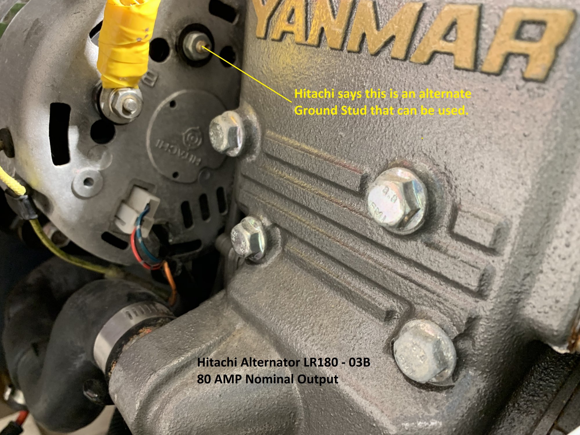
I was confused by empty post in the photo until I saw in the alternator specs that there are 2 ground posts and either one can be used. It was difficult to get my eyeballs on the other post, but with a camera, I get a peek at the post that has the original ground cable. It was difficult to trace it into a bundle but it appears again at the engine post. I think I'm going to have to take out the entire alternator to get this sorted. Any advise is welcome!
Alternator Back.jpg


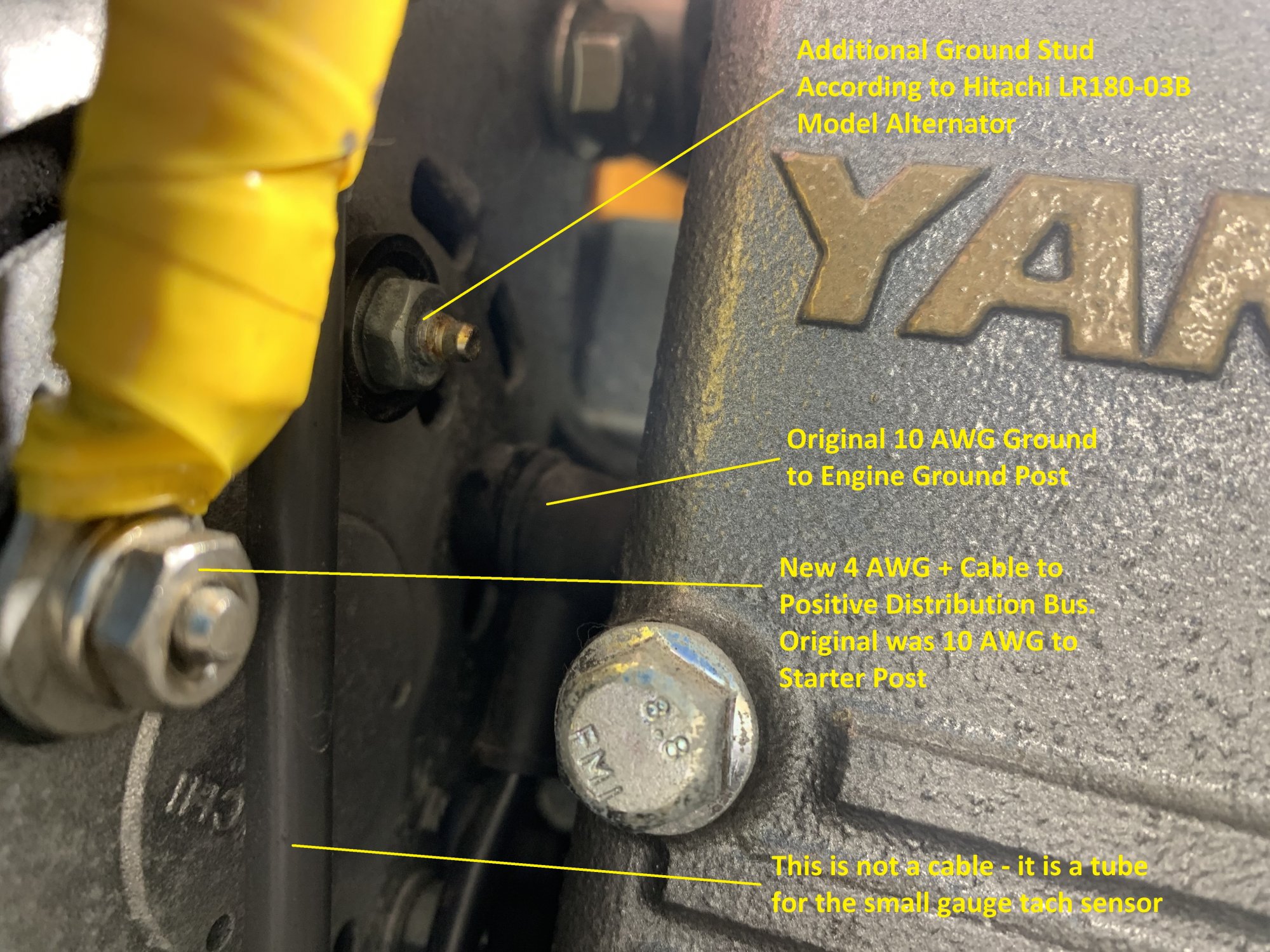
Next, I saw that Compass Marine has a very good "How To" article featuring a replacement alternator with external regulator .... hmmm. Anyway, I see in one of the photos that @Maine Sail has put a jumper between the 2 ground posts. Good idea or not necessary? Attached is one last photo of the Engine Ground. It seems that the terminal lug is in pretty rough condition. I better do something about that too. I wish the access was better. I could barely get a hand in there to take a photo with the phone!
 

Attachments

Last edited:

CYQK

.
Sep 11, 2009
576
beneteau first 42 kenora
looks like a good call to look at your wiring
no doubt the ground is gonna need work
We always look first at the positive side on wiring but neg side is maybe more important
 

capta

.
Jun 4, 2009
4,773
Pearson 530 Admiralty Bay, Bequia SVG
I can't help you with the ground other than to say, IMO, it should be to the engine block and as short as possible.
However, you did not mention any fuse in the hot line. I would consider that a priority, but maybe you do have one? Attached is what we use on both banks.
fuse.jpeg
 

RoyS

.
Jun 3, 2012
1,742
Hunter 33 Steamboat Wharf, Hull, MA
Wonder if two No.10's in parallel instead of one No.4 might serve better for the positive output. Thinking of flexibility and the stress on the small stud. Given the vibration, a single No.4 is pretty stiff and may loosen the nut or even break the stud. Just a thought.
 
Oct 26, 2008
6,081
Catalina 320 Barnegat, NJ
I can't help you with the ground other than to say, IMO, it should be to the engine block and as short as possible.
However, you did not mention any fuse in the hot line. I would consider that a priority, but maybe you do have one? Attached is what we use on both banks.
View attachment 176458
The + cable actually runs thru a service switch first, then to the buss bar with one of those fuse holders and a 100 A fuse. I follow the electrical diagrams that @Maine Sail has provided, which show the alternator ground cable connected to the neg buss bar on the load side of the battery monitor shunt. My ship ground also runs from the buss bar to the engine ground, so I tend to agree with you that running the cable from the alternator to the ship ground shouldn't make much difference, but I could be missing something, so I will follow the electrical diagram when I am able to resolve this issue.
 

capta

.
Jun 4, 2009
4,773
Pearson 530 Admiralty Bay, Bequia SVG
The + cable actually runs thru a service switch first, then to the buss bar with one of those fuse holders and a 100 A fuse. I follow the electrical diagrams that @Maine Sail has provided, which show the alternator ground cable connected to the neg buss bar on the load side of the battery monitor shunt. My ship ground also runs from the buss bar to the engine ground, so I tend to agree with you that running the cable from the alternator to the ship ground shouldn't make much difference, but I could be missing something, so I will follow the electrical diagram when I am able to resolve this issue.
Negative is negative wherever it is. I've always used the engine ground whenever it is easily accessible. The only thought of why MS would recommend attaching it to the negative buss bar is it might be less likely to corrode there. I've always felt more comfortable with a hardened steel bolt with a lock washer into a steel block as my ground connection. But I keep that connection bright and shiny always, as I've found many electrical problems on boats can be traced to a poor (corroded) engine ground connection.
 
Last edited:
Feb 6, 1998
11,674
Canadian Sailcraft 36T Casco Bay, ME
The + cable actually runs thru a service switch first, then to the buss bar with one of those fuse holders and a 100 A fuse. I follow the electrical diagrams that @Maine Sail has provided, which show the alternator ground cable connected to the neg buss bar on the load side of the battery monitor shunt. My ship ground also runs from the buss bar to the engine ground, so I tend to agree with you that running the cable from the alternator to the ship ground shouldn't make much difference, but I could be missing something, so I will follow the electrical diagram when I am able to resolve this issue.
When we build the AMP-IT 80 ER we do tie/bus the two isolated-ground studs together. FLIR thermal imaging showed less localized heat signature when we bussed both neg studs together. This helps to share the load across the rectifier plate inside the alternator. Keep in mind however that the AMP-IT 80-ER is a higher performance alternator, intended to be driven harder than your internal regulator can. Your stock 80A alternator will never be worked as hard, with the internal regulator and thermistor driven self protective temp compensation feature, so bussing the two studs together will likely not be necessary but it certainly won't hurt.

That said wiring the alternator directly to the bank, both positive and negative, will yield as good a performance as you can achieve with that alternator. It will still not be a great performing alternator but better than it came from the factory.

I would also suggest that 4AWG is too big for those studs unless methodically strain relieved so as to not put any undue strain on the studs.. We advise 6GA as the largest direct connection to those studs.. If you need to bump the wire gauge, for volt drop, you run a short distance to a Blue Sea Dual Power Post (two isolated 5/16" studs) where you then increase the wire gauge.

Also be very careful with your service disconnect switch. With an internally regulated alternator it can still boot up with the switch left open and this will eventually blow the diodes. Best to use a lock-out-tag-out type of scenario any time the service disconnect switch is opened. In other-words hang the key on it so you cannot forget to close it when you're done.
 
  • Like
Likes: Leakie Marine
Feb 6, 1998
11,674
Canadian Sailcraft 36T Casco Bay, ME
Negative is negative wherever it is. I've always used the engine ground whenever it is easily accessible. The only thought of why MS would recommend attaching it to the negative buss bar is it might be less likely to corrode there. I've always felt more comfortable with a hardened steel bolt with a lock washer into a steel block as my ground connection. But I keep that connection bright and shiny always, as I've found many electrical problems on boats can be traced to a poor (corroded) engine ground connection.
The engine block is a poor place to attempt to pass large amounts of current through. Doing this typically leads to higher voltage-drop. Multiple dissimilar metals, rust, corrosion etc. can very easily destroy your charging performance due to voltage-drop especially when you have a self-sensed alternator..

If you must connect the alternator B- to the engine, it should be physically stacked onto the engines main B-/neg cable lug for a direct copper to copper connection without passing through the engine block or components to get there.
 
Oct 26, 2008
6,081
Catalina 320 Barnegat, NJ
Great comments. Thanks! I swear, next time I'm at the boat, I will tackle this alternator. The belt is a little loose, anyway, I noticed.
 
Feb 6, 1998
11,674
Canadian Sailcraft 36T Casco Bay, ME
Great comments. Thanks! I swear, next time I'm at the boat, I will tackle this alternator. The belt is a little loose, anyway, I noticed.
At some point upgrade to an externally regulated alternator & regulator and you'll really be happy!
 

Ward H

.
Nov 7, 2011
3,651
Catalina 30 Mk II Barnegat, NJ
At some point upgrade to an externally regulated alternator & regulator and you'll really be happy!
Yep, that is what I did last spring. With Maine Sail's help of course. I used the Balmar MC-614H external regulator with the CMI 90 IR which I c converted to ER (Bought the alt the year before). Fun job, good performance.
 
Feb 26, 2004
22,776
Catalina 34 224 Maple Bay, BC, Canada
Scott, unless the sailing you do includes anchoring out, it's not really worth your time & $$ to go to an external regulator. IIRC, you daysail from your marina. I also assume you know about the inherent limitations of that particular alternator, which MS indirectly mentioned. Putting an external regulator on that particular alternator would make little sense.
 

capta

.
Jun 4, 2009
4,773
Pearson 530 Admiralty Bay, Bequia SVG
The engine block is a poor place to attempt to pass large amounts of current through. Doing this typically leads to higher voltage-drop. Multiple dissimilar metals, rust, corrosion etc. can very easily destroy your charging performance due to voltage-drop especially when you have a self-sensed alternator..

If you must connect the alternator B- to the engine, it should be physically stacked onto the engines main B-/neg cable lug for a direct copper to copper connection without passing through the engine block or components to get there.
Actually, all my engine grounds go to the same bolt, not hither and yon all over the block. Perhaps I should have been more clear.
 
  • Like
Likes: jssailem
Nov 11, 2018
12
Beneteau 45F5 6 Melbourne, Victoria
The + cable actually runs thru a service switch first, then to the buss bar with one of those fuse holders and a 100 A fuse. I follow the electrical diagrams that @Maine Sail has provided, which show the alternator ground cable connected to the neg buss bar on the load side of the battery monitor shunt. My ship ground also runs from the buss bar to the engine ground, so I tend to agree with you that running the cable from the alternator to the ship ground shouldn't make much difference, but I could be missing something, so I will follow the electrical diagram when I am able to resolve this issue.
I would be very careful running through a service switch, if it is opened with the alternator running you could fry your diodes. Perhaps something like a "Alternator Protection Device" or "load dump" would be good insurance if you are setup with one?
https://shop.marinehowto.com/products/sterling-power-12v-transient-voltage-protection-device

Thanks for your post, time for me to check my setup :)
 
Last edited: