Hi, I just bought a CAL34. I am new to sailing and am doing a lot of DIY projects getting my boat ready to sail. It already had a depth finder installed, but is only wired to the head (under the sink.) I need to get the cable through the galley to the electrical panel/chart table. Any advice on how to do this? (Apologize if this is a stupid question, but I am brand new at this stuff...)
Just bought a CAL34, question on wiring Depth Finder
- Thread starter HeatherE
- Start date
Welcome to the forum! Do you know the type of transducer and depth finder? It might make a difference just because some types of cables are easier to splice than others if you need to do something like cut and replace connectors.
In general tools like an electrician’s fishing tape are pretty helpful for projects like that. You’ll need to look at the spaces under the cabin sole and maybe behind cabinetry to see where the wire could be run.
In general tools like an electrician’s fishing tape are pretty helpful for projects like that. You’ll need to look at the spaces under the cabin sole and maybe behind cabinetry to see where the wire could be run.
Hi! Thanks! It's a Raymarine i40. I bought a soldering iron last week (for antenna PL-259 connectors) but haven't done it yet, so splicing and dicing are all new... watching Youtube videos now ") I will grab some electrician's fishing tape on the way to my boat. Appreciate the reply! I wish my Boat manual was more descriptive... seems like a no-brainer for them to map out how to do things like this
I will grab some electrician's fishing tape on the way to my boat. Appreciate the reply! I wish my Boat manual was more descriptive... seems like a no-brainer for them to map out how to do things like this
I will grab some electrician's fishing tape on the way to my boat. Appreciate the reply! I wish my Boat manual was more descriptive... seems like a no-brainer for them to map out how to do things like this An i40 appears to use Raymarine SeaTalk, which I’ve read can be spliced. Never done it myself though so I’d defer to others on how to do that if necessary. In any case you’re better off running the cable in one piece if possible to cut down on the possible failure points. Look around and you’ll probably find enough gaps or other ways to pull the wire with the tape.It's a Raymarine i40.
Welcome to boating unfortunately. Most boat manuals skip the details like how wires are run or the specifics of the structure. Getting to do boat yoga to figure those things out on your own is part of the fun.I wish my Boat manual was more descriptive... seems like a no-brainer for them to map out how to do things like this
Welcome to the forum and congratulations on yyour new sailboat!!......It already had a depth finder installed, but is only wired to the head (under the sink.) I need to get the cable through the galley to the electrical panel/chart table......
Pulling wires and cables through boats in order to install marine electronics can be a pain, espeacilly if you do not have an existing conduit. Some tricks;:
1. Find the shortest concealed route to run the cable.
2. Baby or talcum powder provides lubrication without making a greasy mess of your wiring. It allows wire and cables coated with it to slide more easily past obstructions and around corners. Simply fill your palm with powder and then pull your cable through your hand before you pull it through the boat.
3. Use electricians tape. Pulling Electrical Wires - The Boat Galley
4. Always pull a "messenger line" through with your cable or hose or wire. Make it long enough so that you can always have access to both ends and wont loose it if you use it.
The I40 depth display has the transducer connected directly to it. Its two wires that should lead directly to the transducer.
I'd use heatshrink crimp terminals instead of solder in most instances.
The seatalk connectors on a I40 is old seatalk and/or power. The display puts it's data out on the network, not the other way around. (i.e. the display outputs depth. It doesn't generally display network depth readings)
I'd use heatshrink crimp terminals instead of solder in most instances.
The seatalk connectors on a I40 is old seatalk and/or power. The display puts it's data out on the network, not the other way around. (i.e. the display outputs depth. It doesn't generally display network depth readings)
jssailem
SBO Weather and Forecasting Forum Jim & John
- Oct 22, 2014
- 24,491
The I40 depth display has the transducer connected directly to it. Its two wires that should lead directly to the transducer.
I'd use heatshrink crimp terminals instead of solder in most instances.
The i40 has a manual ( here... https://forums.sailboatowners.com/a...198167/?hash=8a89d9f2eb59425bbf1a665ac240441f )Consider running it to the cockpit
Page 23 begins the cables and connections for the depth sounder and other parts of the system. Looks to be a simple plug and 3 wire connection to the i40.
Attachments
-
5.5 MB Views: 462
Hi! Thanks! It's a Raymarine i40. I bought a soldering iron last week (for antenna PL-259 connectors) but haven't done it yet, so splicing and dicing are all new... watching Youtube videos now
Heather Congrats!!!! Run a new cable point to point avoid soldering. This is counter-intuitive but sometimes it causes corrosion. You better off with a racheting crimper, heat shrink connectors, heat shrink tubing and dialectric grease. Best of luck!
Great progress........remember everything takes 4 times longer on a boat. You are on your way!!
Heather, I hope your project is moving along..... Pick up Nigel Calder's "Boatowner"s Mechanical and Electrical Manual.....It's quite extensive and a lot of it is very technical but a great book to have when you need it.
It's recommended to use tinned copper wiring in boats to avoid corrosion but it's not absolutely necessary. You can solder or use decent crimp connectors. If soldering, I recommend twisting the wires together as a first step using a technique similar to this:
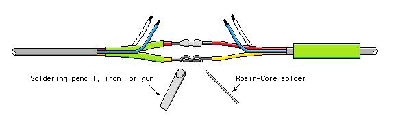
I think the most difficult step for a novice is holding the wires, soldering iron and solder. I like to place the wire under my hand that's holding the iron.
Mechanically connecting (twisting) the wires together creates a stronger connection as well. Once this step is done put a small ball of solder on the iron and hold it against the wire. This ball of solder helps transfer heat to the wire and lets you know when the wire is hot enough. The wire will wick up the solder.
It's recommended to use heatshrink on electrical connections. Dielectric grease is also good. When using heatshrink double wall is preferred because it has a heat activated glue on the inside to help seal it. I personally like using a torch lighter over a heat gun because it is more accurate and more portable. Try to avoid letting the flame touch the heatshrink.
Also check ebay for used extension cable or possibly a bad unit with extension cable included
jssailem
SBO Weather and Forecasting Forum Jim & John
- Oct 22, 2014
- 24,491
Let me start here.
55% of all boat fires are ELECTRICAL IN NATURE !
Give that a moment to sink in.
While solder is used to hold electrical wiring in place in a variety of systems, it has such significant drawbacks in boat wiring that it is dangerous.
A Crimped wire connection is the recommended method.
@Maine Sail has posted this many times here on SBO and has an in depth article about connectors and the tools to use. (recommended reading for the DIY boat owners. Marine Wire Termination - Marine How To )
Some specific highlights regarding solder.
We connect wires to mechanically hold them in place, and to facilitate electrical current to pass through the connection. By proper sizing of your wire and sound connections you will enable the electricity to safely pass through the connection with minimal voltage drop.
The best method of connection is with a proper crimped connector.
55% of all boat fires are ELECTRICAL IN NATURE !
Give that a moment to sink in.
While solder is used to hold electrical wiring in place in a variety of systems, it has such significant drawbacks in boat wiring that it is dangerous.
A Crimped wire connection is the recommended method.
@Maine Sail has posted this many times here on SBO and has an in depth article about connectors and the tools to use. (recommended reading for the DIY boat owners. Marine Wire Termination - Marine How To )
Some specific highlights regarding solder.
- Wire on boats is stranded not solid copper. Reason, everything on a boat is moving. The flexing of the hull as you go up and down waves causes the wire in your boat to flex/pull/push in constant motion. Solid copper metal fatigues and breaks when it is put under continual flexing. Stranded wire takes longer to break. While a single strand may fatigue, the rest of the wires continue doing their job.
- Soldered stranded wire is stiff. It acts like solid copper. The wires will break at the point of solder.
- Solder is a poor conductor. The resistance as electricity tries to move through solder gives off heat. With enough heat created the solder may melt, the connection may fail, the wires may short and the worse may occur - causing your boat to be among the 55%....
We connect wires to mechanically hold them in place, and to facilitate electrical current to pass through the connection. By proper sizing of your wire and sound connections you will enable the electricity to safely pass through the connection with minimal voltage drop.
The best method of connection is with a proper crimped connector.
"The best method of connection is with a proper crimped connector. "
Absolutety agree, with good connectors (heat shrink) and a quality racheting crimper it is much easier than soldering as well.
Absolutety agree, with good connectors (heat shrink) and a quality racheting crimper it is much easier than soldering as well.
Sorry if I misled you with regards to soldering marine wire connections. The only thing that I recommend soldering is the PL-259 coax cable connector. Will need at least 50-75 watt soldering iron (not gun) with a heavy tip approximately 5mm wide. Watch a few you tube videos on how to solder the PL-259 connector; very technique sensitive to achieve a good joint and make sure you test the connector after soldering to ensure that there are no shorts in the assembled connector. (You tube shows you how to do it).I bought a soldering iron last week (for antenna PL-259 connectors) but haven't done it yet
With regards to all other wire connections, I use marine grade mechanical / crimp connectors (Anchor makes quality marine connectors) and marine grade tinned wire. Strip the wires to be joined, thread shrink film over the wire & move it down the wire (away from the crimp), dip the stripped wire in lanocote or other anti corrosive electrical grease, crimp the wire with the appropriate sized connector using a ratcheting crimper, give the wires a tug to ensure a tight connection, and finally pull the shrink film over the crimped joint and apply heat.
If you are going to do your own maintenance and installation of electrical / electronic components, be sure to purchase a good quality ratcheting crimper and a stripping pliers; those tools make the job easier and improve the quality of the crimps. Again, you can watch a few you tube videos for assistance.
Can't offer much advice regarding the depth finder. I usually use the manufacturer's wire and purchase a longer wire from them to make the wire run without splicing, especially if traversing the bilge where a splice could get wet. I agree with Mike's recommendation to have the depth display in the cockpit within sight while at the helm. The display will be useless at the chart table. If you're approaching "skinny" water; need to monitor depth on a continuous basis.
Hi, thanks to all of you for the great advice. I actually paid someone today (and they showed up!) to route my depth finder wire, fix the hole I drilled incorrectly (for the depth finder going from captain's table to cockpit), and connect the antenna (with the existing wire, ) fix my propane solenoid, and fix my navigation light that was out. All in 3 hours of work. (I've spent what feels like decades trying to work through this...) Plus I did a radio check, it worked! I still have more projects, but these were the outstanding ones on my survey so today has been more than glorious!