Grounding two isolated battery banks

Apr 5, 2009
2,819
Catalina '88 C30 tr/bs Oak Harbor, WA
This is a question about proper grounding of the start and house batteries. Is this the proper connections for grounds or should both batteries go to a common neg buss bar?
Current setup. My house battery neg is connected to B- on the alternator. My start neg is connected to a starter bolt. The only connection between the neg terminal on the two batteries is the engine block.
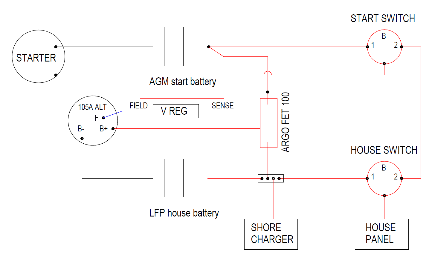
Here is a diagram of my battery connections.
Note that the battery switches only control battery discharge and that charging is independently controlled by an ARGO FET so that both batteries are connected to the alt anytime there is charge current.
The start AGM output goes to a 12BO switch terminal 1
The house LFP output goes to a 12BO switch terminal 1
There is an emergency jumper lead connected to terminal 2 on both switches.
primary curcuit.png
 
Last edited:
Oct 22, 2014
21,107
CAL 35 Cruiser #21 moored EVERETT WA
If I understand, the positive lead from the LFP bank could (through the House and Start switch) be directly connected to the AGM battery.

I am a confessed learner about LFP battery systems, but I believe I have read that directly conntecting the LFP and AGM batteries is a No No...
 
Jan 11, 2014
11,437
Sabre 362 113 Fair Haven, NY
I too am learning about LiFePO batteries, the first thing I've learned is you can't treat them like ordinary LA batteries. The AGM/Start battery is typically connected the LiFePO battery via a DC to DC charger with the charging source connected to the AGM battery.

The schematic you provided will work for LA batteries, I'm less certain about mixed chemistries.

All negative leads should go to a busbar and then to a single point on the engine block and from the busbar back to a ammeter shunt before connecting to the battery.

Here's a link to a recently updated article by MaineSail on LiFePO batteries.

 
Apr 5, 2009
2,819
Catalina '88 C30 tr/bs Oak Harbor, WA
If I understand, the positive lead from the LFP bank could (through the House and Start switch) be directly connected to the AGM battery.

I am a confessed learner about LFP battery systems, but I believe I have read that directly conntecting the LFP and AGM batteries is a No No...
The direct connection that you mention is only for an emergency connection and not for interconnecting the two banks and has never been used in 24 years on Papillon.

For the past 24 years, when we come onto the boat, we turn start switch to 1 and turn house switch to 1 and they are not touched until we leave the boat when they are both turned to off. All house loads come only from the house bank. All starting loads (and engine instruments) come only from the start battery. The two batteries are never connected together by wire.
The closes that they come is through the battery combiner. Up until now, that was a diode-based battery combiner that allows current to only flow out from the alternator and into each battery. I plan to upgrade this to a FET based combiner so that the alternator does not need to raise the output voltage by 0.7v to overcome the diodes. Both of these methods will work just fine to combine the different types for charging. 14.0V is perfect for my LFP and just a bit low for the AGM but not harmful.
 
  • Like
Likes: jssailem
Oct 22, 2014
21,107
CAL 35 Cruiser #21 moored EVERETT WA
Having a defined procedure for managing your boat system is essential and safe.

I was looking at the wiring and considering a crew member or a new owner that is not yet versed on the specifics of your system.
 
Apr 5, 2009
2,819
Catalina '88 C30 tr/bs Oak Harbor, WA
I too am learning about LiFePO batteries, the first thing I've learned is you can't treat them like ordinary LA batteries. The AGM/Start battery is typically connected the LiFePO battery via a DC to DC charger with the charging source connected to the AGM battery.

The schematic you provided will work for LA batteries, I'm less certain about mixed chemistries.

All negative leads should go to a busbar and then to a single point on the engine block and from the busbar back to a ammeter shunt before connecting to the battery.

Here's a link to a recently updated article by MaineSail on LiFePO batteries.

I have heard before that only one connection to the engine. I do have only one connection to the engine but it only connects to the start battery neg terminal. For the house ground, the only connection is to the B- post on the alternator. The B- is connected to the shunt and then house neg post with 2-O cable. The B+ terminal goes to the battery combiner and then to the start battery with 2-O. There is currently no ground lug on the engine for the house battery. This was all done professionally before I bought Papillon 24 years ago.
If I connect both the start and house batteries to a negative charge buss, I will still need to have the 2-O to B-. My main confusion is to I also then have a large wire (2AWG?) to the engine block? That is what I am leaning towards now.

Thanks for reposting Rods article from 2009. I think I read it for the first time somewhere around 2013 and have re-read it many times. Much of it is still good and there are some things that have changed. Note, I have been actively designing my LFP system for 3-4 years and have read (according to my wife) WAY TOO MANY technical articles and forums on the subject.

See response to John above.

There are two big dangers from connecting an alternator to a LFP which are excessive heat, and high power disconnect. The common use of DC2DC chargers is intended to resolve both of these issues but is not the only way to that goal.

This system also has the effect of making it impossible to disconnect the alternator from a load. Anytime the alternator is sending power, It is connected to both batteries because that connection is before the switch which only controls the load and not the charge. The danger from LFP is that the BMS can disconnect to LFP cells from charge or discharge whenever it decides it needs to and that can be a very bad thing for the alternator. In my case, if that happens the current is still going to the AGM and there is no spike to fry the diodes.

The B2B charger will allow limit how much current is going to the LFP which will slow it down to safe levels. If you have a normal internally regulated alternator, this is the only way that you can avoid releasing the magic smoke from it. I have an Ample Power 105A alternator with an external regulator. My regulator has a PWM controller on the field wire so I can dial it down until it runs well below the 200ºF that is considered to be the max safe temperature. It also has a thermostat with the sensor bolted to the B+ terminal that will sample the internal temperature and shut it off it the temp gets to 190º.
 

Ward H

.
Nov 7, 2011
3,651
Catalina 30 Mk II Barnegat, NJ
The only connection between the neg terminal on the two batteries is the engine block.
The only way I see there might be a connection between the two batteries is through the alternator case if the case is in fact grounded.
Couldn't that negative path, through the alt case, brackets, etc to the block and then to the start battery cause a voltage drop in charging voltage for the start battery?
A negative buss bar in the engine bay properly wired to one at the house bank would seem a simple solution.

Does the ARGO Fet pass the same voltage through to both batteries? Is that why the V sense for the regulator is on the start battery side?
 
Apr 5, 2009
2,819
Catalina '88 C30 tr/bs Oak Harbor, WA
Having a defined procedure for managing your boat system is essential and safe.

I was looking at the wiring and considering a crew member or a new owner that is not yet versed on the specifics of your system.
I pity the next owner because I have soooo many systems that require knowledge. The hydronic heating has 5 manual valves to direct the flow as required. I have diagrams with circles and arrows and a paragraph on the back of each. I am not up to 27 yet but getting there. :dancing::dancing::dancing:
Sing it with me as the chorus comes round "You can get anything you want..."
 
Last edited:
Apr 5, 2009
2,819
Catalina '88 C30 tr/bs Oak Harbor, WA
The only way I see there might be a connection between the two batteries is through the alternator case if the case is in fact grounded.
Couldn't that negative path, through the alt case, brackets, etc to the block and then to the start battery cause a voltage drop in charging voltage for the start battery?
A negative buss bar in the engine bay properly wired to one at the house bank would seem a simple solution.

Does the ARGO Fet pass the same voltage through to both batteries? Is that why the V sense for the regulator is on the start battery side?
If I run everything to a neg bus and then from there to the alt, I would probably make a 2AWG cable from B- to the block for starter cranking.
The Argo FET works just like a diode combiner in that it passes current to both in a one-way connection. Being FET based instead of diode based, there is almost no voltage loss. 0.01v at low current, 0.1v at 100A max current. The sense wire for the alternator is on the start battery so that if there is a BMS disconnect, I will still be connected to a current carrying wire. This will be very important while I am still using my diode-based combiner, but I will probably move it to the to the alternator side with the FET so that if there a failure in the FETs, the alt will see the voltage rise and shut it down. I will probably be limiting my 105 alternator to about 60A to start with and adjust from there based on temperature and belt dust.
 
  • Like
Likes: Ward H
Jan 11, 2014
11,437
Sabre 362 113 Fair Haven, NY
The primary reason for only one negative connection to the engine block is to keep the engine out of the circuit, that is out of the current flow. A second consideration is simplicity in the wiring, having all negatives to to a bus bar makes tracing things easier.

Since the big issue is keeping the engine block out of the circuit, it is reasonable to have more than one cable connected to the engine block at one connection point. Thus, you could connect the alternator negative to the same post as cable from the negative bus bar, doing so would probably reduce the cable size for the alternator negative as the distance is short. For a 5 foot cable carrying 100 amps a 6 ga cable would be adequate.

A variation on this would be using a power post near the engine. The negative bus bar, batteries, and alternator negatives go to the post and a single large gauge cable goes from the post to the engine block.

The same principles hold true for the positive side. Run all charging sources, alternator, solar, charger, to a positive busbar, then one cable to AGM battery then one cable to the B2B charger and the LiFePO battery. This protects the alternator in case the BMS suddenly shuts things down and simplifies the wiring.

The 1-2-B switches are both potential points of human induced error and failure, as we all know, to err is human. I would eliminate that potential point of failure. It seems much more likely that a human will err than a battery failing.
 
Apr 22, 2011
865
Hunter 27 Pecan Grove, Oriental, NC
I have three lfp batteries in parallel that are connected to pos and neg bus bars.The neg bus bar is connected with a 1awg cable to the engine block. The agm start battery neg and the alternator neg are also connected to the engine at the same point. The alternator positive is connected to a maintenance switch and then on to the pos bus for the lfp batteries. The agm start battery pos goes to the starter and in turn to engine instruments.

My new addition to the charging system is a Balmar 100 ah alternator with smart controller. This allows me to eliminate the need for the 20amp b to b charger that I had installed and get max alternator output to the lfp batteries. I am using the b to b with an agm setting to charge the agm battery from the house bank. The b to b has a manual on/off switch for use when needed.

Lots of different ways to get the job done.
 
  • Like
Likes: Hayden Watson
Jan 11, 2014
11,437
Sabre 362 113 Fair Haven, NY
I have three lfp batteries in parallel that are connected to pos and neg bus bars.The neg bus bar is connected with a 1awg cable to the engine block. The agm start battery neg and the alternator neg are also connected to the engine at the same point. The alternator positive is connected to a maintenance switch and then on to the pos bus for the lfp batteries. The agm start battery pos goes to the starter and in turn to engine instruments.

My new addition to the charging system is a Balmar 100 ah alternator with smart controller. This allows me to eliminate the need for the 20amp b to b charger that I had installed and get max alternator output to the lfp batteries. I am using the b to b with an agm setting to charge the agm battery from the house bank. The b to b has a manual on/off switch for use when needed.

Lots of different ways to get the job done.
How are you protecting the alternator if the LPO BMS suddenly shuts down charging?
 
Apr 5, 2009
2,819
Catalina '88 C30 tr/bs Oak Harbor, WA
How are you protecting the alternator if the LPO BMS suddenly shuts down charging?
by connecting both the AGM start battery (which cannot be taken offline) and the LFP which can be taken off my the BMS with a FET battery combiner. It provides complete isolation of the two banks when there is no charge current coming from the alternator. It provides a very low resistance closed circuit when there is charge current coming from the alternator.
This means that if the LFP is cut off by the BMS, the alternator is still sending the current to the start battery. No KaBoom.
 
  • Like
Likes: jssailem
Nov 6, 2017
76
Catalina 30 5611 Stratford, Ct
Although I am not an expert in this subject, combining two battery chemistries in the same circuit is not the best idea, especially when lithium batteries are in the mix. The reason for that is the differences in charging profiles needed to get the maximum life from your very expensive battery system. You are also right to be worried about the BMS shutting down your lithium batteries and frying the alternator. Depending on where your alternator is getting its field current depends on the alternator output. If the regulator is looking at the lithium batteries for that signal and it is set to a profile for lithium batteries you will likely overcharge the AGM battery. If your regulator is looking at the AGM for field current and the regulator is set for an AGM charge profile the lithium batteries will be undercharged. No matter which way you do this one of your battery banks will suffer. One way to fix this would be to install a lithium start battery to eliminate having two battery chemistries. In our boat, we have a 120 amp alternator with an external regulator that is set up to charge the 210 amp/hr Lifeline AGM house batteries and a DC/DC charge to charge the group 24 AGM start battery whenever there is oil pressure in the engine. The regulator is set to an AGM profile as is the DC/DC charger. The alternator and battery temperature are monitored by the regulator. This setup allows fast charging of the house batteries and the DC/DC charger handles the start battery. You could use a system like this to charge your batteries and use the regulator to help protect the alternator from BMS shut down. For better protection, you could charge the start battery with the alternator and use multiple DC/DC chargers to maximize charging time on the lithium battery bank. Since the AGM will never shut down the alternator would be well protected and the lithium will get the charging profile that is right for it.
AS for your grounding question, we did ground both banks to the engine with a heavy ground cable. We did this because in doing research about grounding systems in boats we concluded that all systems should be grounded to the engine. Our alternator however is isolated and is only connected to the house batteries. I understand the reason for doing this is mostly due to steel and aluminum hulls to prevent galvanic corrosion, but that is a totally different subject.
 

walt

.
Jun 1, 2007
3,511
Macgregor 26S Hobie TI Ridgway Colorado
I have not followed all the details (and think the OP understand this system much better than I will from reading here) but lets say you have a single ground bus that all the current flows into. You now want to ground this to the engine block or something like that. If everything is working properly, there should be no current flowing from the wire connecting the ground bus to the engine block. If you did, it would mean that current is flowing into the water through metal parts of the engine (ie, prop, shaft). This is a ground fault, a doc GFCI would be tripping, you would have corrosion etc.

I can think of one important safety reason where you would have a lot of current flowing in the wire between the bus and the block and that is if you have an AC fault such as the AC hot accidentally getting connected to the engine block. In this case, your system should be set up so that this AC fault blows a breaker either on the boat or from the shore power. So I believe (could be wrong) that the bus to engine wire only needs to be large enough to carry enough current to blow whatever breaker is protecting the AC power. Seems that 10 gauge would cover making sure the AC breaker blew.

It could be more complicated than this.. not sure.
 
Jan 11, 2014
11,437
Sabre 362 113 Fair Haven, NY
I have not followed all the details (and think the OP understand this system much better than I will from reading here) but lets say you have a single ground bus that all the current flows into. You now want to ground this to the engine block or something like that. If everything is working properly, there should be no current flowing from the wire connecting the ground bus to the engine block. If you did, it would mean that current is flowing into the water through metal parts of the engine (ie, prop, shaft). This is a ground fault, a doc GFCI would be tripping, you would have corrosion etc.

I can think of one important safety reason where you would have a lot of current flowing in the wire between the bus and the block and that is if you have an AC fault such as the AC hot accidentally getting connected to the engine block. In this case, your system should be set up so that this AC fault blows a breaker either on the boat or from the shore power. So I believe (could be wrong) that the bus to engine wire only needs to be large enough to carry enough current to blow whatever breaker is protecting the AC power. Seems that 10 gauge would cover making sure the breaker blew of any typical AC fuse size for this application.

It could be more complicated than this.. not sure.
For the AC side of the system is this more or less correct, however, the OP is talking about the DC side. It too needs to have all the negatives (there is no ground in DC) connected in one place on the engine block.
 
Apr 5, 2009
2,819
Catalina '88 C30 tr/bs Oak Harbor, WA
I have not followed all the details (and think the OP understand this system much better than I will from reading here) but lets say you have a single ground bus that all the current flows into. You now want to ground this to the engine block or something like that. If everything is working properly, there should be no current flowing from the wire connecting the ground bus to the engine block. If you did, it would mean that current is flowing into the water through metal parts of the engine (ie, prop, shaft). This is a ground fault, a doc GFCI would be tripping, you would have corrosion etc.

I can think of one important safety reason where you would have a lot of current flowing in the wire between the bus and the block and that is if you have an AC fault such as the AC hot accidentally getting connected to the engine block. In this case, your system should be set up so that this AC fault blows a breaker either on the boat or from the shore power. So I believe (could be wrong) that the bus to engine wire only needs to be large enough to carry enough current to blow whatever breaker is protecting the AC power. Seems that 10 gauge would cover making sure the AC breaker blew.

It could be more complicated than this.. not sure.
The only large current carried by the engine is the starting current because is it only connected electrically by wire to the positive side. That is why the wire to the engine starter mounting bolt is 2AWG. I have had some posts from Maine Sail on a different forum and will take both batteries to the neg buss and then connect to the engine and alternator engine and alternator from there.
 
Apr 5, 2009
2,819
Catalina '88 C30 tr/bs Oak Harbor, WA
Although I am not an expert in this subject, combining two battery chemistries in the same circuit is not the best idea, especially when lithium batteries are in the mix. The reason for that is the differences in charging profiles needed to get the maximum life from your very expensive battery system. You are also right to be worried about the BMS shutting down your lithium batteries and frying the alternator. Depending on where your alternator is getting its field current depends on the alternator output. If the regulator is looking at the lithium batteries for that signal and it is set to a profile for lithium batteries you will likely overcharge the AGM battery. If your regulator is looking at the AGM for field current and the regulator is set for an AGM charge profile the lithium batteries will be undercharged. No matter which way you do this one of your battery banks will suffer. One way to fix this would be to install a lithium start battery to eliminate having two battery chemistries. In our boat, we have a 120 amp alternator with an external regulator that is set up to charge the 210 amp/hr Lifeline AGM house batteries and a DC/DC charge to charge the group 24 AGM start battery whenever there is oil pressure in the engine. The regulator is set to an AGM profile as is the DC/DC charger. The alternator and battery temperature are monitored by the regulator. This setup allows fast charging of the house batteries and the DC/DC charger handles the start battery. You could use a system like this to charge your batteries and use the regulator to help protect the alternator from BMS shut down. For better protection, you could charge the start battery with the alternator and use multiple DC/DC chargers to maximize charging time on the lithium battery bank. Since the AGM will never shut down the alternator would be well protected and the lithium will get the charging profile that is right for it.
AS for your grounding question, we did ground both banks to the engine with a heavy ground cable. We did this because in doing research about grounding systems in boats we concluded that all systems should be grounded to the engine. Our alternator however is isolated and is only connected to the house batteries. I understand the reason for doing this is mostly due to steel and aluminum hulls to prevent galvanic corrosion, but that is a totally different subject.
I covered most of this in post #6.
  • First off, I am not combining chemistries. They are completely isolated from each other except during charging at which time the combining is done by the Victron Argo FET combiner. LFP bulk at 14.0v, AGM bulk at 14.2v: AGM slightly undercharge which while this is not optimal, it is not bad and will have minimal effect on the AGM lifespan. Close enough to play nice together. In all cases the two banks will be fully isolated for all loads and only combined on the charge circuit which is seperate from the load circuit.
  • By sending alternator charge current to batteries through the Argo FET combiner, the AGM will be constantly connected even if the LFP is disconnected so no diode Boom.
  • Alternator will be getting sense voltage from AGM so that if LFP cuts out the alter will still be under control instead of going to max charge.
  • Regulator has PWM control on field wire to manually limit max field current to de-rate output.
  • Regulator monitors alternator case temperature and shuts down output if it goes over my max setpoint which will be 90ºC.
  • for negative battery connections, for short term I will add a 2AWG jumper between the alternator B- and starter to close the charging circuit on the AGM. Eventually, I will rewire both batteries to the neg buss.
 
  • Helpful
Likes: Ward H
Apr 5, 2009
2,819
Catalina '88 C30 tr/bs Oak Harbor, WA
Hayden, yes you did. cagreen75's post was more about NON LiFePO4 systems than anything else. I applaud your patience in replying. I sure sounds like you've got this well covered. All the best.
Thanks Stu. I am fairly happy and comfortable with my positive side means and methods but knew that there was something wrong with how the negative was wired but was not sure how to fix it. It was done professionally before I purchased Papillon 24 years ago and I had never really looked at it, just assuming that everything was A-ok. This past week I started digging into it because my LFP build will completely fill my mounded battery box so I will need to move the shunt to the outside. The more I looked and chased wires, the less I liked it. It has always worked but not in the preferred manner.
Rod sent me this photo and I will be changing
neg buss.jpg
mine to be something like it. I have new red and black 300A buss bars on order to form the basis.