Electrical Symbol for preheat solenoid

Fred

.
Sep 27, 2008
517
Catalina 28 mkii 745 Ottawa, Ontario, CA
There may be a better place to post this question but since it is related to my Cat 28 electrical system here goes....
I am attempting to understand the operation of the "PreHeat Solenoid". I am not familiar with the schematic symbol used in the Universal manual. How does the "I" terminal behave?

1713037574712.png
 

jssailem

SBO Weather and Forecasting Forum Jim & John
Oct 22, 2014
22,746
CAL 35 Cruiser #21 moored EVERETT WA
Here is the way MaineSail diagrams the preheat solenoid.

1713099137199.jpeg


As I decode the image, when you energize the S lead (press the glow plug switch) the solenoid is energized. The I lead directs power to the Glow Plug. When you release the glow plug switch the Solenoid de powers (S lead) and the power is directed to the starter. Through the I lead.

MaineSail has a good discussion about the Universal wiring that may be of assistance.


As an aside MaineSail gave freely of his knowledge helping many sailors before being stricken by a stroke. His website is a treasure trove of ideas. If you can, he could use your help financially to keep this resource available.
 
  • Like
Likes: JamesG161

Fred

.
Sep 27, 2008
517
Catalina 28 mkii 745 Ottawa, Ontario, CA
I’ll check out the link. Thanks. The diagram provided has no connection to the”I” terminal so it doesn’t provide me with anymore insight as to its function.
 

jssailem

SBO Weather and Forecasting Forum Jim & John
Oct 22, 2014
22,746
CAL 35 Cruiser #21 moored EVERETT WA
Where do you find the image of the solenoid? Looking at the Universal engine manual I did not find a “Preheat Solenoid”.
Is this an add to your system and you are looking for the way to connect the S and I wires?
 

Fred

.
Sep 27, 2008
517
Catalina 28 mkii 745 Ottawa, Ontario, CA
Also what confuses me is that the schematic symbol I posted implies 5 connections on the solenoid. I understand the operation of a 4 terminal solenoid ( 2 for coil, 2 for contacts)
 

Fred

.
Sep 27, 2008
517
Catalina 28 mkii 745 Ottawa, Ontario, CA
Actually its on page 97 of the manual that I found online (pg 26 of my paper manual)
1713121535062.png
1713121535062.png
 

Fred

.
Sep 27, 2008
517
Catalina 28 mkii 745 Ottawa, Ontario, CA
From what I see in some forums, some of these engines wired the glow plugs directly through the keyswitch (Bad!!!) without the solenoid so maybe that was the practice for earlier boats. (mine is a 2004)
 

Fred

.
Sep 27, 2008
517
Catalina 28 mkii 745 Ottawa, Ontario, CA
What I am really after is understanding the warning buzzer circuit. My buzzer can at times sound very anemic before the engine is started. I've replaced the buzzer. The "I" terminal of the solenoid is shown to be connected through the 10A circuit breaker to the ""P" terminal of the alarm buzzer" so that is why I'm interested in the function of this terminal.
 
Mar 6, 2008
1,293
Catalina 1999 C36 MKII #1787 Coyote Point Marina, CA.
The buzzer or the soanalert is 24 volts and it's12v power path is through a 1k resistor that is located near the fuel pump, so it is not as loud as it can be. The resistor is drawn just below the solenoid in your schematic diagram. You have to redraw this diagram to understand the diagram.
Here you will find a simplified diagram
 
Apr 10, 2010
106
Catalina 310 166 Dartmouth, Nova Scotia
Generally speaking the "I " terminal refers to the ignition or start switch where it would get its power from. Or at least that is the situation on my 310 with glow plugs on the 25XPC universal engine, a kubota really.
 
  • Like
Likes: jssailem

Fred

.
Sep 27, 2008
517
Catalina 28 mkii 745 Ottawa, Ontario, CA
Thank you Joe. The redrawn schematic is very helpful and makes the oil pressure switch logic must clearer. Thanks! Note that the ground path for the buzzer is actually through the 1k resistor in parallel with the lift pump. In any case when working properly, the buzzer is plenty loud. I believe that I read somewhere that the connections at the lift pump are prone to corrosion and can be flaky. I will inspect them when I get to the boat.

I am still puzzled by the "I" terminal of the pre-heat solenoid and why it is tied in to the lift pump and the buzzer circuit. It seems to me that the circuit would still function correctly with that terminal disconnected.
 
Sep 24, 2018
3,261
Catalina 30 MKIII Chicago
What you are seeing is a generic schematic design of a relay. Terminal I is switched between the two unlabeled contacts/terminals. Mainesail's drawing is easier to understand by most boaters
 
  • Like
Likes: jssailem
Feb 26, 2004
22,979
Catalina 34 224 Maple Bay, BC, Canada
You might answer the solenoid wiring question by doing a google search on how to wire an electric solenoid. There are many explanations of this simple device wiring.
 
  • Like
Likes: jssailem

Fred

.
Sep 27, 2008
517
Catalina 28 mkii 745 Ottawa, Ontario, CA
Believe me, I googled this in every way possible including using Google lens to search for the schematic symbol. I am actually an electrical engineer and ever aware how solenoids/relays work but the intended function of this one stumps me.
 
Sep 24, 2018
3,261
Catalina 30 MKIII Chicago
I am still puzzled by the "I" terminal of the pre-heat solenoid and why it is tied in to the lift pump and the buzzer circuit. It seems to me that the circuit would still function correctly with that terminal disconnected.
I'd imagine it's tied to a line coming off of the ignition switch so none of these devices (glowplugs, buzzer, etc) are able to be active with the key in the off position. Feel free to fill me in if I'm missing something.
 

Tedd

.
Jul 25, 2013
772
TES 246 Versus Bowser, BC
It looks to me like the intent is for the glow plugs to go off as soon as there's oil pressure. Something like that would be normal for an automotive diesel system.
 

Fred

.
Sep 27, 2008
517
Catalina 28 mkii 745 Ottawa, Ontario, CA
A post that @jssailem sent me suggests that the PreHeat Solenoid operates as follows:
1) with the coil not energized: the "I" terminal and the two main terminals are free floating (i.e. open)
2) with the coil energized: the "I" terminal and the two main terminals are all connected together (i.e. shorted)

This makes sense in the operation of the circuit in that while the oil pressure switch is open (i.e. the engine is not running) AND the Preheat Solenoid is energized (I.e. in the momentary key switch position) the Lift Pump is activated (temporarily) by the +12v coming from the "I" terminal. When the key switch is released from the momentary position the glow plugs are no longer heating and the lift pump is expected to be energized by the running engine (i.e. sufficient oil pressure).

In the case of loss of oil pressure the lift pump is deactivated.

Note that if you release the momentary key switch before you press the engine start button (which I normally do) the glow plugs are no longer heating and the lift pump is not energized.
 
  • Like
Likes: jssailem

Fred

.
Sep 27, 2008
517
Catalina 28 mkii 745 Ottawa, Ontario, CA
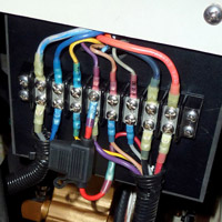
To close off this thread… I found the problem with my low oil alarm. Two blue wires are crimped together on the terminal of the 10 A pre-heat breaker. This crimp was bad and corroded, probably got worse when I had to remove it last season to replace a heat exchanger hose. I put on a new crimp terminal and everything works well now. Thanks for all your input!