My 500A DC Ammeter suddenly started providing current readings as high as 900 Amps with no decimal and fluctuating between 150-900 amps. The boat and the ammeter are 3 years old and have worked flawlessly until today (typical range was 0-30 Amps, always with a decimal). My system is a 12 volt system and no I don't have anything that would draw anywhere near 900 amps. It showed this reading even when everything on the board was shut down.
I don't think the cause is corrosion as the shunt and connections are pretty clean.
As a first step, I'm trying to figure out the manufacturer of the Ammeter. I think it might be Paneltronics but their part number is 570-006B not 570-006.
In addition, I'm trying to figure out whether there is anyway I might be able to test whether the meter is working properly or confirm that the shunt is working properly.
Anyone know what Catalina put on their 2016 385s? I'm going to reach out to the dealer in the morning but thought someone here might know.
Any suggestions on what might have caused this, which Ammeter I have, and any other steps you might suggest?
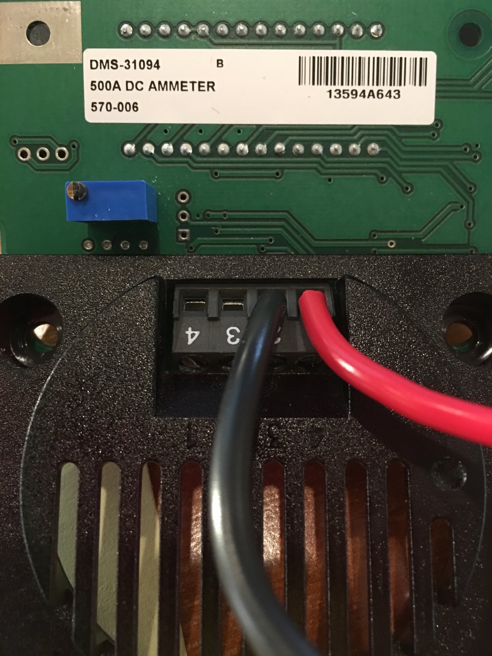
This is the label on the Ammeter:
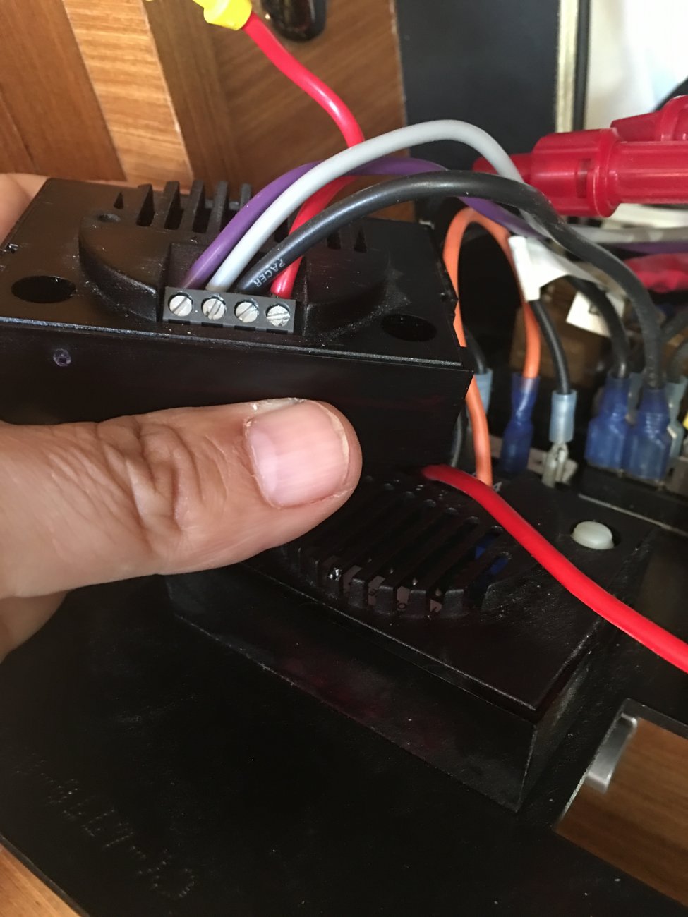
These are the wires going into the Ammeter
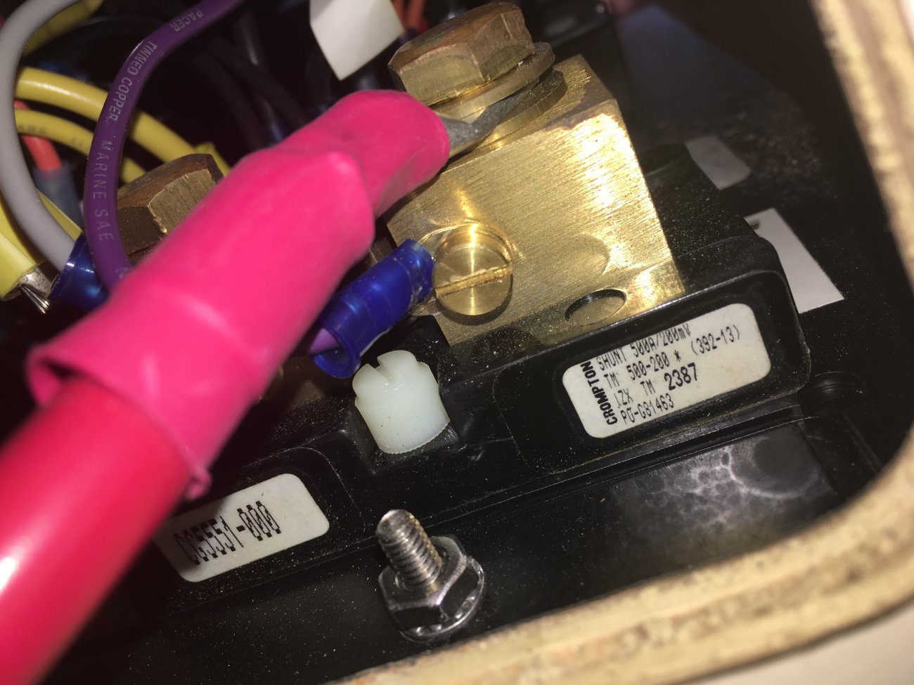
This is the back side of the shunt
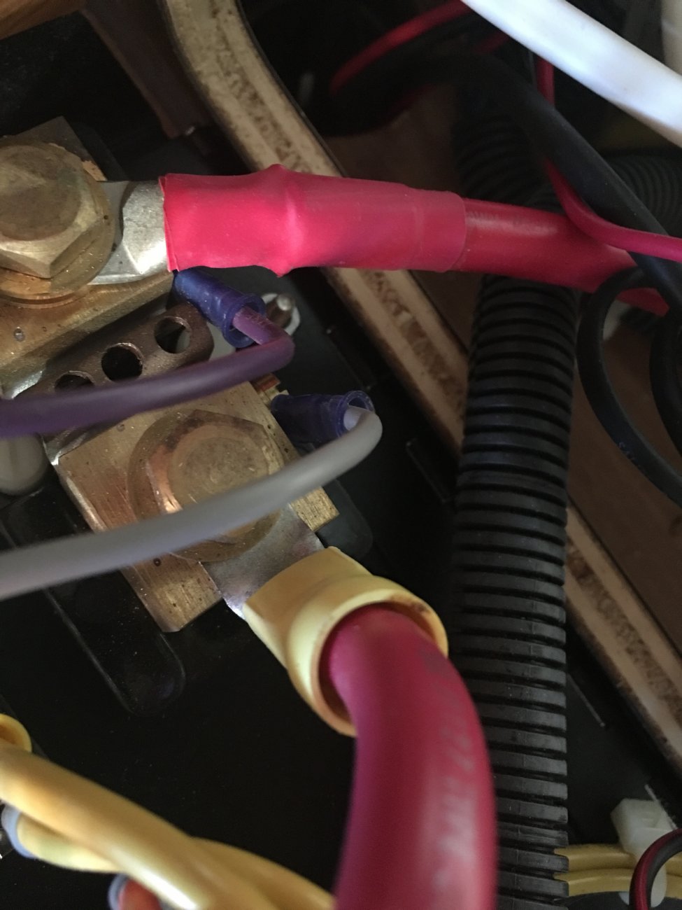
Here is the top side of the shunt:
I don't think the cause is corrosion as the shunt and connections are pretty clean.
As a first step, I'm trying to figure out the manufacturer of the Ammeter. I think it might be Paneltronics but their part number is 570-006B not 570-006.
In addition, I'm trying to figure out whether there is anyway I might be able to test whether the meter is working properly or confirm that the shunt is working properly.
Anyone know what Catalina put on their 2016 385s? I'm going to reach out to the dealer in the morning but thought someone here might know.
Any suggestions on what might have caused this, which Ammeter I have, and any other steps you might suggest?
This is the label on the Ammeter:
These are the wires going into the Ammeter
This is the back side of the shunt
Here is the top side of the shunt: