
Since acquiring Smitty one system that has constantly given me a hassle has been the wet exhaust. In 2011, our first year together, the stock exhaust split while powering out of the river right as we were getting ready to set the sails. That spewed how sea water and soot all over engine. We powered back in and I assessed the problem. I found the crack, actually that was easy because the exhaust riser had split into two pieces. Later this lead to an engine stall because the soot had clogged my factory air filter. This probably contributed to rust on the engine and it was difficult to clean all the residual soot off the entire engine.
In researching a replacement I found out that Catalina made these custom for each boat model and in order to get a replacement, I would have to send the old one to California, it would take 4 weeks and cost like $300. Another options would be to have one made locally. My cousin has a machine shop and I took it to him. It would cost about $200 at most machine shops to fabricate. He doesn’t have a pipe bender so he could not do it. But he did weld the broken one back together. A third option that I got from reading at Sail Boat Owners was to make my own pipe from the home store.
For the remainder of 2011, I built my own exhaust riser out of black steel. It was quick fix and relatively easy. But it didn’t fit well and made the area along the bulk head cramped.
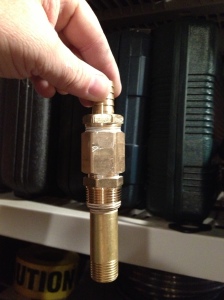
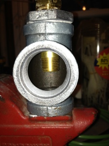
 Factory Exhaust Riser
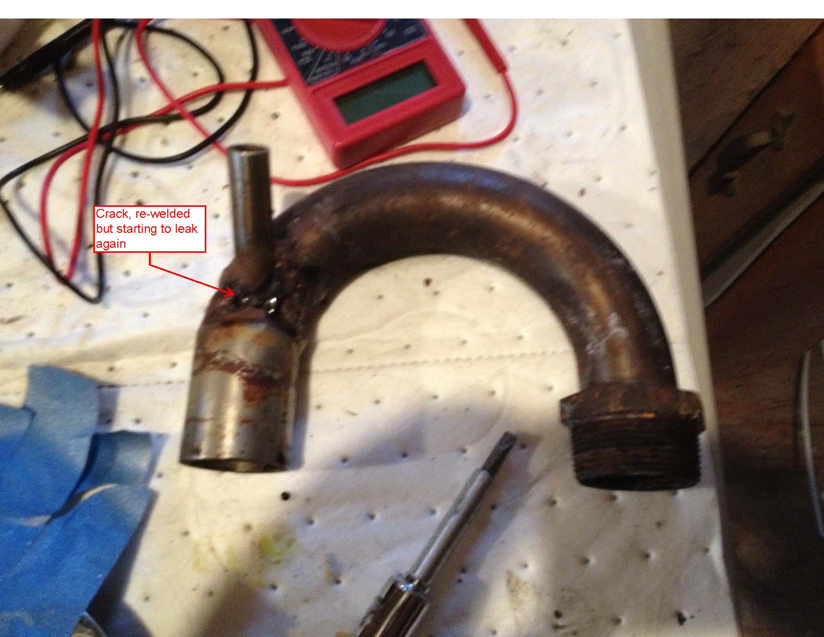
My cousin welded my original exhaust riser back together and I put that back on for the 2012 season. But at the end of the season, I removed the riser as part of repainting the engine and found that it was starting to leak again at the weld.
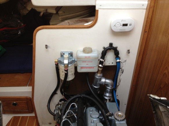
This lead to me making a custom exhaust riser that would be a permanent fix. I wanted it to be made of commonly available pieces so that I could replace it easy in the future. Also, since I had moved out the bulkhead by about 3 inches, I wanted to take advantage of that space and have an unwrapped riser for easy inspection.
For materials I chose to go with black steel instead of galvanized steel pipe. There is some concern with galvanized steel when heated causing health problems. However, the heat needed is much higher than produced by a small diesel like mine, but I decided to avoid this concern altogether and go with black steel. I also went with brass for the water portion of the mixing elbow. This was mainly due to availability. I would have stayed with black steel but they don’t carry the parts needed at the local home store. For a thread sealant I used Hercules Real-Tuff based on a previous recommendation from MaineSail. It has a good temperature range and doesn’t contain zinc or other metals that could lead to corrosion problems.
When I first had to make my temporary exhaust riser the hardest part of the project was separating the riser from a 90 degree elbow with a flange. That piece couldn’t be reproduced easily and took two large pipe wrenches (3 footers I had for work) and a 5 foot extension bar we used to put extra torque on the wrenches. But eventually we (my buddy Tim and I) got it separated. Since then I have used the Real-Tuff every time I have put it together and you don’t have to torque the pieces together to get tight treads. As a result, you can separate it easier if you need to make changes or clean parts.
The factory exhaust riser was 1 1/4 inch schedule 80 stainless steel pipe. The inner diameter is 1.28 inches. The only reason I can think that they used the schedule 80 was they were bending it fairly sharply and then welding to it. From a strength perspective, there is no reason schedule 40 wouldn’t work in this application. The inner diameter for schedule 40 pipe is 1.38 inches. That’s about a 15% increase in size. I had thought about going bigger but it didn’t seem necessary. My temporary exhaust riser from 2011 was 1 1/2 inch schedule 40 black iron and that was really too large to fit the area. The 90 with the flange coming off the exhaust is 1 1/2 inches and the factory riser immediately reduced to the 1 1/4 inches. So I mimicked this set up with a 1 1/2 by 1 1/4 inch reducing coupling.

Next I threaded a 4 inch piece of pipe into the coupling followed by a street 90 and then a t-fitting. On the bottom of the tee fitting I placed another 4 inch piece of pipe as a point to connect the exhaust hosing leading to the muffler. On the factory riser, it was just smooth pipe that fit into the hose and then was held with two hose clamps. So I am doing the same and the threads on the pipe should affect the connection because there is enough flat section above the threads to get the first hose clamp on.
For the water injection portion, I used brass. A combination of 3/4 inch and 1/2 inch. Iused a 3/4 by 1/2 reducing coupling. Some of these couplings have the 1/2 inch threads all the way through the fitting. If you don’t have threads all the way through the interior, you could complete the threading with a tap. This allows a 1/2 inch pipe (3 inches long) to be threaded into the interior side of the reducing coupling. A hose barb can be threaded into the top of the reducing coupling. For this one I had to use an additional coupling in the middle due to a lack of pieces at the home store I went to. Also, this is a potential site for galvanic corrosion. So I will likely to some research with some suppliers I use at work and remake this portion with black iron to remove the problem.
The whole apparatus I made above was than threaded into the top of the t-fitting via a 1 1/2 by 3/4 inch reducing coupling. So the water is injected in the middle of the 1 1/2 inch inner diameter of the pipe while allowing exhaust to flow around it before mixing.

The pipe that was threaded into the inside of the3/4 by 1/2 inch reducing coupling brings the injection point for the water down to the lower portion of the opening. This was done to prevent water from back flowing into the exhaust and hydro-locking the engine.
The rest of the pieces were assembled to complete the mockup. I then dry fit the piece and made a couple of adjustments to the angles where several parts met.

I painted the completed piece with Rustoleum high heat paint and installed it on the engine.
I ran the engine this weekend. I let it get up to temperature and ran it with a load at about 1,500 RPM in gear, tied up to the dock. I let the engine run for about an hour and took some readings with my IR thermometer.
 Temperature readings in degrees Fahrenheit
I also checked the temperatures on the new bulkhead and those all stayed around 70 degrees. I will keep monitoring temperatures and update if I make any changes. Now, no more planned projects for this year. Bend on the sails and get out there. Can’t wait to sail Maine later this year.
Cross posted on my blog.
In researching a replacement I found out that Catalina made these custom for each boat model and in order to get a replacement, I would have to send the old one to California, it would take 4 weeks and cost like $300. Another options would be to have one made locally. My cousin has a machine shop and I took it to him. It would cost about $200 at most machine shops to fabricate. He doesn’t have a pipe bender so he could not do it. But he did weld the broken one back together. A third option that I got from reading at Sail Boat Owners was to make my own pipe from the home store.
For the remainder of 2011, I built my own exhaust riser out of black steel. It was quick fix and relatively easy. But it didn’t fit well and made the area along the bulk head cramped.
 Factory Exhaust Riser
My cousin welded my original exhaust riser back together and I put that back on for the 2012 season. But at the end of the season, I removed the riser as part of repainting the engine and found that it was starting to leak again at the weld.
This lead to me making a custom exhaust riser that would be a permanent fix. I wanted it to be made of commonly available pieces so that I could replace it easy in the future. Also, since I had moved out the bulkhead by about 3 inches, I wanted to take advantage of that space and have an unwrapped riser for easy inspection.
For materials I chose to go with black steel instead of galvanized steel pipe. There is some concern with galvanized steel when heated causing health problems. However, the heat needed is much higher than produced by a small diesel like mine, but I decided to avoid this concern altogether and go with black steel. I also went with brass for the water portion of the mixing elbow. This was mainly due to availability. I would have stayed with black steel but they don’t carry the parts needed at the local home store. For a thread sealant I used Hercules Real-Tuff based on a previous recommendation from MaineSail. It has a good temperature range and doesn’t contain zinc or other metals that could lead to corrosion problems.
When I first had to make my temporary exhaust riser the hardest part of the project was separating the riser from a 90 degree elbow with a flange. That piece couldn’t be reproduced easily and took two large pipe wrenches (3 footers I had for work) and a 5 foot extension bar we used to put extra torque on the wrenches. But eventually we (my buddy Tim and I) got it separated. Since then I have used the Real-Tuff every time I have put it together and you don’t have to torque the pieces together to get tight treads. As a result, you can separate it easier if you need to make changes or clean parts.
The factory exhaust riser was 1 1/4 inch schedule 80 stainless steel pipe. The inner diameter is 1.28 inches. The only reason I can think that they used the schedule 80 was they were bending it fairly sharply and then welding to it. From a strength perspective, there is no reason schedule 40 wouldn’t work in this application. The inner diameter for schedule 40 pipe is 1.38 inches. That’s about a 15% increase in size. I had thought about going bigger but it didn’t seem necessary. My temporary exhaust riser from 2011 was 1 1/2 inch schedule 40 black iron and that was really too large to fit the area. The 90 with the flange coming off the exhaust is 1 1/2 inches and the factory riser immediately reduced to the 1 1/4 inches. So I mimicked this set up with a 1 1/2 by 1 1/4 inch reducing coupling.

Next I threaded a 4 inch piece of pipe into the coupling followed by a street 90 and then a t-fitting. On the bottom of the tee fitting I placed another 4 inch piece of pipe as a point to connect the exhaust hosing leading to the muffler. On the factory riser, it was just smooth pipe that fit into the hose and then was held with two hose clamps. So I am doing the same and the threads on the pipe should affect the connection because there is enough flat section above the threads to get the first hose clamp on.
For the water injection portion, I used brass. A combination of 3/4 inch and 1/2 inch. Iused a 3/4 by 1/2 reducing coupling. Some of these couplings have the 1/2 inch threads all the way through the fitting. If you don’t have threads all the way through the interior, you could complete the threading with a tap. This allows a 1/2 inch pipe (3 inches long) to be threaded into the interior side of the reducing coupling. A hose barb can be threaded into the top of the reducing coupling. For this one I had to use an additional coupling in the middle due to a lack of pieces at the home store I went to. Also, this is a potential site for galvanic corrosion. So I will likely to some research with some suppliers I use at work and remake this portion with black iron to remove the problem.

The whole apparatus I made above was than threaded into the top of the t-fitting via a 1 1/2 by 3/4 inch reducing coupling. So the water is injected in the middle of the 1 1/2 inch inner diameter of the pipe while allowing exhaust to flow around it before mixing.

The pipe that was threaded into the inside of the3/4 by 1/2 inch reducing coupling brings the injection point for the water down to the lower portion of the opening. This was done to prevent water from back flowing into the exhaust and hydro-locking the engine.

The rest of the pieces were assembled to complete the mockup. I then dry fit the piece and made a couple of adjustments to the angles where several parts met.

I painted the completed piece with Rustoleum high heat paint and installed it on the engine.

I ran the engine this weekend. I let it get up to temperature and ran it with a load at about 1,500 RPM in gear, tied up to the dock. I let the engine run for about an hour and took some readings with my IR thermometer.
 Temperature readings in degrees Fahrenheit
I also checked the temperatures on the new bulkhead and those all stayed around 70 degrees. I will keep monitoring temperatures and update if I make any changes. Now, no more planned projects for this year. Bend on the sails and get out there. Can’t wait to sail Maine later this year.
Cross posted on my blog.
Last edited:
")


