Circuit troubleshooting

Status
Not open for further replies.

kerryb

.
Nov 23, 2009
37
Beneteau Oceanis 400 Lighthouse Point, FL


Joined: Nov 2009
Posts: 11


Electrical Troubleshooting


Trying to trace down a drain problem with my batteries. First, should there be any sparks when connecting the positive line from the alternator to the battery switch? With voltmeter on the alternator cable and negative switch terminal, I get about 8 mV reading. There is another smaller wire connected to the positive terminal that appears to be connected to the amp light. This is supposed to furnish the initial trigger for the alternator to start charging. When I remove this wire from the alternator, the sparks disappear when connecting the alt cable to the switch. Could the lamp being out cause this sparking to happen? The wire in question goes through a little device that I cannot find in the wiring diagram. Hopefully, I have given enough information for someone understand.
Oh, the alternator does charge without the idiot light in the circuit.

Kerry
 
Oct 2, 2006
1,517
Jboat J24 commack
If the diodes fail in the alternator they can drain a battery.

I will usually connect a meter between the + on the battery and and the cable that goes there if i get a voltage reading i start disconnecting things till it goes to 0

If you had a dead short i learned from a friend to use a auto 12 volt headlight between the battery and cable as it will glow BUT not dead short and allow you to again start disconnecting things to find the bad circut
 
Feb 6, 1998
11,760
Canadian Sailcraft 36T Casco Bay, ME
Tracing parasitic loads..

I have seen a lot of questions over the years about parasitic battery loads, current draw on your battery even when everything appears to be turned off. Here's a quickie on how I isolate and find them.

In order to trace ghost or parasitic loads you'll need the proper tool. You'll want a multi-meter that will read DC amps / millivolts out to the thousandths or the hundredths.

These meters can be had very cheaply these days and while the cheapies might not be the most accurate you are only looking to eliminate or make the current draw disappear on the meters screen.

If you find you have a parasitic load you can easily track it down by disconnecting load wires from the back of the panel , one by one while monitoring the meter, or anywhere a load pulls off the circuit down stream/current of the meter.

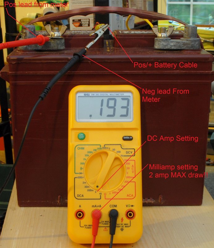
To test for this you simply insert the meter between the positive post of the battery and the positive battery cable. Please only do this with everything turned OFF!!! I can't stress this enough. ALL loads must be turned off including the battery switch before inserting your multimeter.

The fuses in multimeters, for reading milliamp DC current, are usually a 2 amp fuse MAX. Do not blow this fuse or the meter will no longer work. Fixing it will most likely require you to disassemble the meter to change the circuit board mounted fuse.

Once you've connected the positive lead from the multi-meter to the positive battery post, and the negative wire from the meter to the battery cable, set your meter to read milliamps and plug your cables into the appropriate sockets on the meter.

Once you flip on the meter it will either read .000, meaning you have no parasitic load, or a current flow such as the one pictured below.

Please note that I set this up in my garage and used a Sensibulb as my current draw hence the teeny tiny wire I labeled "battery cable". Your battery cable would be considerably larger..

Of course, like anything, there are more ways than this to achieve the same outcome but I find this to be the easiest and one of the fastest. A clamp meter that does DC amps/millivolt would actually be easier but they tend to hunt beyond .01 and can be tough to zero out beyond .1. I chose not to use my clamp meter for this because I know most sailors don't own a DC clamp meter..


Dec 25, 2008
1,580
catalina 310 Elk River
I will also reiterate what Maine has said. Once you have the current meter inserted in the circuit be dam sure you don't inadvertently turn on a load, because if it is greater than 2 amps you will blow the fuse in the meter provided if it has one.
In reference to your post, the fact that the light is out has no effect on your errant current draw. In fact it could only have your reported effect if it was always on.
Your account of the problem is a little hard to understand, but it almost sounds like you have an external regulator and that my be the "little device" you have referred to which may be the source of the problem.
On my alternator on the C130 it has an internal regulator and is just sensing the voltage level from the battery. Do you have a schematic?
 
Last edited:
Feb 26, 2004
23,353
Catalina 34 224 Maple Bay, BC, Canada
Is your alternator wired to your 1-2-B switch or to your house bank?
 

kerryb

.
Nov 23, 2009
37
Beneteau Oceanis 400 Lighthouse Point, FL
Stu, I have it to the house bank. Using newly installed separator or solonoid to keep battery banks isolated. Maine Sail, I will try this, (again) already blew the fuse and I had it in the 10 amp side. I will try to follow your instructions and see what I find. I guess I should have all the connections when I test. I will remove the apm light wire from alternator if I see a drain to try and confirm that it is coming from that source.
 
Jun 6, 2006
6,990
currently boatless wishing Harrington Harbor North, MD
Guys, he found the leak already

when he disconnedted the idoit light the sparks stopped.
Now all we have to do is diagnose the idiot light circuit.
Kerryb, when the light comes on or goes off does it do so in a gradual fassion or like a switch was thrown?
There are two ways to rig the circuit. One uses bat voltage on one side and alternator voltage on the other. As the alternator voltage "comes on line" the idiot light will gradually go out. As the engine slows and alternator voltage drops off the light will start out dim and get brighter.
The other way to rig the circuit is to have a voltage sensor (zenor diode usually) that "goes off when the alternator voltage gets to a set level. This could be the unknown box in the circuit but can't tell from the discription.
If you could discribe what the idiot light circuit is connected to after the box it would help.
To answer the questions, yes there are usually sparks when you connect any hot wire. It does not take much voltage to get a spark (the red ones are lower voltage while the bright white ones are higher amps and volts)
I don't understand the circuit so I don't know if the lamp being out is causing the current. It could be so as when you disconnect things in the right way you could energize the lamp.
 

kerryb

.
Nov 23, 2009
37
Beneteau Oceanis 400 Lighthouse Point, FL
The results are in, partially!
House Bank:
Battery switches off: 1.76 m amps, pulled each wire from alternator, still 1.76 m amp. Pulled alternator cable, no change. Pulled separator cable, went to zero.
Turned battery switch on, had to use the 10 amp side of meter. meter read 3 amps.
Conclusion: Is 1.76 m amp acceptable for device like sure-power battery separator?
3 amps seems to be a big problem as all breakers on the panel were off. Need to test by pulling each item from the breakers until I find offending circuit. Does this sound like right approach?

Starter Battery bank:
With battery switch in off position, meter read 4.56 m amps. Pulled seperator and reading went to zero. Is this acceptable?
With battery switch on and separator off the circuit, reading .08 m amp.

After disconnecting and taping the wires on the Alt. light, the sparks was not there when I connected the alternator positive to the switch.

Took some pictures of the alternator connections and some relays that the wires attach to:
I do have the wiring schematics for the engine that I have been using to try and make sense of how it is setup. Can take a picture of that ans upload if it helps.
 

Attachments

kerryb

.
Nov 23, 2009
37
Beneteau Oceanis 400 Lighthouse Point, FL
Bill, the idiot light is blown at present. I have ordered a replacement that will be in next week. Problem is, I do not not what caused it to blow. I tried to test the wire at the alternator side to the idiot light side today. Was getting 100 or so ohm reading. I think it is joined by another wire, the brown and yellow on in the relay image I sent. (center relay) If so, I am not sure what the ohm readings would mean.
The unknown box is the (relay for a better term) in the lower left of the alt. back image. Another device I do not understand is the the black inline device at the green part of the relay. This is connected to the alt. pos terminal, joined by the red wire to the alternator.
 
Feb 26, 2004
23,353
Catalina 34 224 Maple Bay, BC, Canada
You keep mentioning separator. What is that? The old days they used "isolators" to keep batteries separated, but most folks who have already been smart enough to get their alternator output off the switches and onto the house bank know that already and use combiners or echo chargers or another simple switch, so the relays or switches should have any draw at all.

In this case, pictures simply don't help because we don't know where the other end of the wires goes! :cry:
 
Jan 22, 2008
8,050
Beneteau 323 Annapolis MD
If I follow the bouncing ball correctly, there is no bulb in the idiot light, so might the light socket be shorted? I hope all those loose, dangling wires will be decently supported when you're done troubleshooting?
 
Oct 2, 2006
1,517
Jboat J24 commack
Or you could hook up a two prong auto head light like the meter and nothing will blowup :) because If you blew the 10 amp fuse you have a big draw
 
Dec 25, 2008
1,580
catalina 310 Elk River
You first need to study the circuit diagrams to understand what is going on. If you start disconnecting things and get confused you will really dig yourself a hole. So make sure you label clearly. Understanding the circuit design and following the current flow within is key to success.
If you can post them, some forum participants may be able to help clarify.
 

kerryb

.
Nov 23, 2009
37
Beneteau Oceanis 400 Lighthouse Point, FL
Stu Jackson, the separator is a smart solenoid by sure power, model 1314. I posted on the a week or so ago. Had isolator in the system but when I had the alternator repaired (replaced regulator), they said the alternator was not designed to run through isolator. Since isolator tested bad, I replaced with the smart solenoid.
Ron, yes, I will tie-wrap the jumbled mess into a little less mess. :dance:
OK, here is the wiring diagram. Except for a few jigs and jags it is pretty much what I have.
 

Attachments

kerryb

.
Nov 23, 2009
37
Beneteau Oceanis 400 Lighthouse Point, FL
Well, don't look like the wiring images are readable. Sorry.
 
Mar 6, 2008
1,498
Catalina 1999 C36 MKII #1787 Coyote Point Marina, CA.
Use a red LED with a 300 Ohm resistor in series with it instead of an Amp Meter. If the LED lights up then there is current flow. You can not blow the LED as the resistor will limit the current. LED will light up at about 10mA. If your 10Amp fuse blew - then you have a major problem It takes about 10Amps to light up the head light of a car!
Have you checked the float switch on the bildge pump?
I hope this helps.
 

kerryb

.
Nov 23, 2009
37
Beneteau Oceanis 400 Lighthouse Point, FL
Joe, with the new fuse, actually a new multimeter, I measured 3 amps on the house bank with the battery switch on. I just replaced the float switch with a sensing type, but I have it wired to the hot side of the house battery which did not indicate any current when checked with the battery switch off. I will be going over to the boat today to re-confirm the 3 amp reading, and then start looking in the panel, which looks like a nightmare. May send some images of it so everyone knows what I am dealing with. Boat was built in France and still has most of the hardware that came with it. The breakers lead to a buss bar where the cables from the battery are terminated. The wires are marked with tiny little plastic clips on each wire - both ends. Other equipment that has been added over the years are either fused to the buss bar or want to say run through breakers laying inside the compartment, but not sure .
I probably need to add another breaker board, but the buss bar is looking pretty loaded, and is complicated for me to figure out the logic of how it works.

Will try the led suggestion for quick initial test and to leave in circuit while looking for the culpert that is leaking.

I don't know if I mentioned it, but I believe I was hit by lightening about 1-2 months ago. I have had the following instruments and equipment repaired or replaced so far.
Auto pilot head unit, wind speed transducer and head unit (both circuit boards blown on the head unit, ie. seatalk and measuring side - Raymarine ST6000+), speedometer head. Also, the main board on Lectrasan head unit, bilge pump float switch, all three batteries, (house bank gel cells about 4-5 years old, start AGM about 2 years old)
I have a truecharge 20 shore power charger that I am very suspect on and have it out of the circuit for now. When it was in circuit, I could see the voltage dropping on the battery monitor over a period of time where I was recording the observation. (this was before Maine Sail showed me the correct procedure to connect the meter for measuring current. Also pull a 2400 watt inverter out because I could see the sparks from the hot line connection, kinda like those on the alternator. After reading the manual, this is expected during installation, so at present, have no reason to believe it is gone.
Thanks for listening to my rambling and ranting. Hope I have not over done it.
 
Jan 22, 2008
8,050
Beneteau 323 Annapolis MD
" I just replaced the float switch with a sensing type, but I have it wired to the hot side of the house battery which did not indicate any current when checked with the battery switch off."

I'm sure you know those sensing float switches constantly draw current- albeit small- even when in the "pump-not-on" state? Like a TV, it is never totally "off".
 
Feb 26, 2004
23,353
Catalina 34 224 Maple Bay, BC, Canada
Ahem...getting hit by lightning and having someone else rewire parts of your boat and having a nightmare behind the panel are kinda giveaways, don't ya think? Like, that's very important information for us to know. It appears what it would be very important for you to start to trace each and every single circuit and figure out what you need to get your second DC panel up and running, if indeed that's required. While your parasitic load may be indicative of a single problem that we've been trying to help you with, having now just learned of your larger problems may make that just a small part of the overall issues you face. There are many fine books available that explain electrical circuits and basic panel wiring designs, layouts and connections. I know I didn't have a clue about boat wiring when I first bought our boat 12 years ago, but I studied and learned, with the help of the kind of folks on this board.
 

kerryb

.
Nov 23, 2009
37
Beneteau Oceanis 400 Lighthouse Point, FL
OK, back from the boat with test results. After pulling everywire from the buss bar, and still getting the 3 amp draw when switches are on, I decided to disconnect the alternator wire from the house switch. Mind you, it was on the hot side of the switch. This eliminated the draw down to zero per my xantrex battery monitor. ( realized it was already giving me the information that the meter connection was giving) What was and is confusing me is the fact that with the switch tin the off position, there was no drain, although the alternator wire was connected to the hot side of the switch.
Anyway, I put the alternator wire back on the hot side of the house bank switch and turned it back on. I pulled the idiot light, first the small red wire and the draw goes away. (see 1st image) I put it back on and remove the black wire connected to the positive post (middle right side) and again the draw goes away. Now in image 2, follow thered wire back and you can see part of a connector. This is like a y connector where the black and red wire are connected. If you follow the black wire from the alternator, you will see a device inline, right about where the green (relay?) is located.I am not sure what this device is and how it works into the setup. Anyone reconize what it might be?
Now, back to the black and red wire connection via the Y connector. From here, it gets connected to a brown and yellow wire that ends up at the idiot light. It is joined by another brown and yellow wire the comes from the relay in the previous images. But, it also is connected to the orange wire that goes into the green (relay?) in image 2. This I think was added as I cannot find it in the Perkins wiring diagram for the boat. The green and white wire goes up to the refrig unit on top of the motor, so I think it was added when evry that was put on the boat.(before me)
Now back to the drain: At the bottom of the Y connector, I am able to pull the wire that goes to the idiot light and relay, leaving the red wire and the black wire with the funny little device inline connected to the alternator. This configuration has the 3 amp drain. This leads me to believe that the alternator still has a problem, unless the funny little device is doing something and is broken.
I am adding the breaker images for kicks. I have been the only one adding and removing things since I have owned the boat. I am sure much was done prior to my ownership 5 years ago.
Oh, and I am using Nigel Calder's book, Boatowner's Mechanical and Electrical Manual, second edition for reference in addition to the Perkins engine manual.
 

Attachments

Status
Not open for further replies.