Do you have a recommendation?I sent you a PM
Those mechanical thermostates are pretty much junk. The only thing that they can measure is if the evaporator coil is is frozen or not but do nothing about the air temperature inside the box.
Add heat-sink cooling fins to alternator?
- Thread starter Hayden Watson
- Start date
I replaced my mechanical thermostat which can only sample the temperature of the aluminum evaporator plate. It does not sample the temperature of the air inside the box. It also makes the compressor run at max speed which uses much more energy that would be required at a lower speed.Do you have a recommendation?
I installed one of these in place of the mechanical thermostat which has the dual effect of running the compressor at the slowest and most efficient speed and turns it on and off based on the temperature of the box. I set mine to turn off at 32º and back on at 39º. It will run for 10-30 minutes and then be off for 2-3 hours. I also installed a PWM fan on the condenser which lets me slow the fan down which also increases the efficiency in my cool PNW climate. This would not be needed for someone in the hotter regions.
I side benifit is that I can always tell exactly what the temperature inside the fridge is.
Make sure that you get the 12v version of the thermostat because they also make 120ACv and 220ACv models.
It really does not matter what brand you have. They are all based on the same compressors. Almost all are the Danfoss BD50F with a few using the smaller brother the BD35F.Hayden, is the digital temperature controller a plug and play type of install when replacing the mechanical controller?
I have an Isotherm unit.
Not quite plug and play but almost.
- You need to connect the control to +&- 12v. [I tapped it off from the main connection to the fridge control board.]
- You need to drill a hole through the side of the icebox and install the temperature probe inside. [It sould be away from the evaporator coil and preferably not against the side of the box. I used a couple of plastic wire ties to connect it to the bottom side of a shelf I built in the box.]
- Connect the cooling relay to the "T" and "C" terminals on the compressor control board which is where your current thermostat is connected.
0-ohms = 2000rpm.
1500-ohm = 3500rpm
Attachments
-
272.8 KB Views: 298
Great info, Hayden. Now I've got another project on my list.
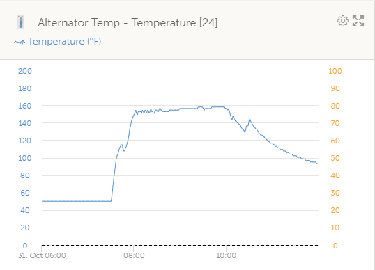
Refering waaaay back to your original post, I also have an Ample Power alternator. Fortunately, it keeps ticking away. I added a sensor to my Venus GX to record the temps. The graph below is from motoring from Port Townsend back to Port Ludlow in a dead calm. I've got the alternator temp setting dialed back in the MC-614 and the Ample is happy charging the 400 AH LFP bank when motoring. HOWEVER, it does not push the voltage high enough to bring the bank to full because of the temperature limit.
I just picked up an unused Balmar AT-165 J10 at a good price. My assumption is that I'll be able to push the Balmar harder and it has a higher output. Balmar says the J10 pulley in the serpentine kit will fit the Ample alt, so it's going to continue life aboard as a spare. Now I just need to find a serpentine kit for the 3GM30F for cheap. As long as the Ample keeps going there's no rush to make the change.
to get back sort of the original thread. Ample aka David Smead, did 2 books in 1995 and 1998, Pics attached that were the revolutionary item that kicked off, in my view, the multi stage charging revolution. Pics attached. I had the great fortune of buying a Nor'sea 27 in about 1998 that had been completely outfitted with AMPLE Power equipment, including the monitor, alternator, regulator and 2-4D Sonnenschein AGM's. WOW, what a package that one. I installed a Ample latching relay as a solar regulator. Following the disastrously and inaccurate article in Practical Sailor the Ample Business faded and Balmar kinda picked up and ran with the torch to what we know today. ANYTHING AMPLE built was built right and they did have large frame product also available.. David passed several years ago.
Attachments
-
 434.4 KB Views: 173
Very nice to get a full log of what is going on. I have a question and a couple of comments.Great info, Hayden. Now I've got another project on my list.
Referring waaaay back to your original post, I also have an Ample Power alternator. Fortunately, it keeps ticking away. I added a sensor to my Venus GX to record the temps. The graph below is from motoring from Port Townsend back to Port Ludlow in a dead calm. I've got the alternator temp setting dialed back in the MC-614 and the Ample is happy charging the 400 AH LFP bank when motoring. HOWEVER, it does not push the voltage high enough to bring the bank to full because of the temperature limit.
View attachment 221364 View attachment 221365
I just picked up an unused Balmar AT-165 J10 at a good price. My assumption is that I'll be able to push the Balmar harder and it has a higher output. Balmar says the J10 pulley in the serpentine kit will fit the Ample alt, so it's going to continue life aboard as a spare. Now I just need to find a serpentine kit for the 3GM30F for cheap. As long as the Ample keeps going there's no rush to make the change.
In your log, when did you arrive at Pt Ludlow?
I set my max alternator temperature at 95ºC or 200ºF per a recommendation from Mainesail. I currently limit the output to 60A because that is about the most that I can get from the 3/8" V-belt.
You said "HOWEVER, it does not push the voltage high enough to bring the bank to full because of the temperature limit." The limiting factor is the current. The alternator could have pushed 400A and the voltage would not have gone much if any higher until the batteries were nearly full. The temp setting limits the current output which is what causes the heat. The greater output from the alternator would reduce the time before the voltage starts to go up but would not change the voltage much. On my most recent cruise, I depleted my house bank down to about 10%SOC after almost 4-days at anchor. I planned to motor from Eagle Harbor to Shallow bay which would only take a few hours and at 60A I would not get a full recharge. I put my Honda in the inflatable which I always toe with the bow tight to the stern of Papillon and ran the shore power chord out to it. With the 60A from the alternator and the 60A from the Victron IP22's, I was able to get a full charge before I reached Shallow Bay. There was very little change in the battery voltage for the first 3-hours and it stayed in the 13.3v range.
Right around 10:30 AM. There's a little bump after that, when I motored from the pumpout to my slip.In your log, when did you arrive at Pt Ludlow?
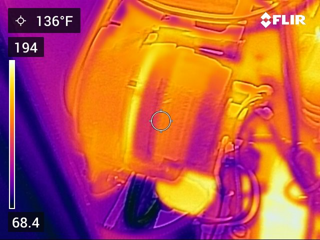
Yeah, I found out that the temp sensor lug doesn't measure the hottest part of the alternator. Parameter AL1 in the MC-614 was set to 75°C when the photo below was takenI set my max alternator temperature at 95ºC or 200ºF per a recommendation from Mainesail. I currently limit the output to 60A because that is about the most that I can get from the 3/8" V-belt.
 . It's now set to 50°C.
My understanding is that the Balmar MC-614 only regulates voltage. It has no knowledge of current. So the only way to limit temperature is to limit voltage. Now, if I had a Wakespeed or a Zeus VR, I could manage the current...so I'm working on obtaining a Zeus for testing.You said "HOWEVER, it does not push the voltage high enough to bring the bank to full because of the temperature limit." The limiting factor is the current. The alternator could have pushed 400A and the voltage would not have gone much if any higher until the batteries were nearly full. The temp setting limits the current output which is what causes the heat.
One more comment. It's entirely possible that I have a different parameter set incorrectly in the Balmar. It's easy to screw up the programming. But if everything is set the way I recorded it, the temperature limits the voltage, nothing else.
Last edited:
I agree. David's stuff was great with one caveat. He never conceived of any battery being able to stay in bulk for many hours on end. Mine was on the boat when I got it and that was 25-years ago, and it is still working great. That said, I do baby it and limit the max output so that it does not cook itself.to get back sort of the original thread. Ample aka David Smead, did 2 books in 1995 and 1998, Pics attached that were the revolutionary item that kicked off, in my view, the multi stage charging revolution. Pics attached. I had the great fortune of buying a Nor'sea 27 in about 1998 that had been completely outfitted with AMPLE Power equipment, including the monitor, alternator, regulator and 2-4D Sonnenschein AGM's. WOW, what a package that one. I installed a Ample latching relay as a solar regulator. Following the disastrously and inaccurate article in Practical Sailor the Ample Business faded and Balmar kinda picked up and ran with the torch to what we know today. ANYTHING AMPLE built was built right and they did have large frame product also available.. David passed several years ago.
This is a common misunderstanding of the regulators cause and effect. The current is the cause, the voltage is the effect. When you "set" the voltage, you are setting the max voltage that the regulator will allow at the battery. This voltage is product of the current being sent to it from the alternator and the resistance of the battery. Ohms law V = Ir or current times resistance. The regulator limits the voltage by reducing the current output to the level that will not drive the voltage above the set point based on the ever-changing internal resistance of the battery.Right around 10:30 AM. There's a little bump after that, when I motored from the pumpout to my slip.
Yeah, I found out that the temp sensor lug doesn't measure the hottest part of the alternator. Parameter AL1 in the MC-614 was set to 75°C when the photo below was taken
View attachment 221380
My understanding is that the Balmar MC-614 only regulates voltage. It has no knowledge of current. So the only way to limit temperature is to limit voltage. Now, if I had a Wakespeed or a Zeus VR, I could manage the current...so I'm working on obtaining a Zeus for testing.
One more comment. It's entirely possible that I have a different parameter set incorrectly in the Balmar. It's easy to screw up the programming. But if everything is set the way I recorded it, the temperature limits the voltage, nothing else.
My observation that the voltage is being limited led me to assume that it was due to heat, but you're right, as the alternator heats up current would be reduced to moderate heat production while maintaining the voltage setpoint. Which means the setpoint is the issue.This is a common misunderstanding of the regulators cause and effect. The current is the cause, the voltage is the effect. When you "set" the voltage, you are setting the max voltage that the regulator will allow at the battery. This voltage is product of the current being sent to it from the alternator and the resistance of the battery. Ohms law V = Ir or current times resistance. The regulator limits the voltage by reducing the current output to the level that will not drive the voltage above the set point based on the ever-changing internal resistance of the battery.
At this point, I've hijacked your thread far too much. I did find some possible culprits, which I'll share in a new thread.
Bottom line is that the Ample Power alternators were well made. I don't disagree at all with wanting to keep it. Just about any aluminum heat sink would be bendable enough to fit, but would it help? That's beyond my ability to calculate.
Last edited:
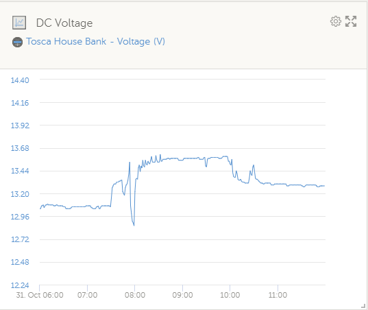
Your set point is probably fine. The reason that it is not getting to your set voltage has nothing to do with the set point and everything to do with the way that an LFP battery takes current. Your battery will take far more current than your alternator can produce. You can see this by looking at the voltage on your battery graph. It appears that you started the engine at 7:30 with battery voltage about 13.0v. In the LFP world this is a low SOC down in the 30% range. When I see anything with a "12" in it, I know that I need to make some serious Amps because it goes down very fast from that point. A resting voltage of 13.0v is about 30% SOC and 13.3v is about 90% SOC. Once you started motoring, the voltage under your full charge current (cold alternator / little limiting.) went all the way up to 13.3vMy observation that the voltage is being limited led me to assume that it was due to heat, but you're right, as the alternator heats up current would be reduced to moderate heat production while maintaining the voltage setpoint. Which means the setpoint is the issue.
At this point, I've hijacked your thread far too much. I did find some possible culprits, which I'll share in a new thread.
Bottom line is that the Ample Power alternators were well made. I don't disagree at all with wanting to keep it. Just about any aluminum heat sink would be bendable enough to fit, but would it help? That's beyond my ability to calculate.
 On an FLA that much current on a 30% SOC battery would have pushed the voltage from 11.75v up over 13v and in less than an hour would have been at set point with only a fraction of the current that the alternator can produce.
 The LFP battery voltage receiving a large charge current will only be 1v to 2v more than the resting voltage so you will never see the set point until your battery is at 98% SOC. I only set my regulator set point shortly after leaving the dock when the shore charger has topped it off because any other time other than 100% SOC you will not see the set point. I do my regulator adjustments only when the battery app shows that the alternator is only sending less than 20A to the battery so that I know I am in the CV portion of the charge cycle.
No worries about hijacking the thread, anything LFP is fine with me.
Meanwhile back at our originally scheduled programming, even though I am a Structural Engineer, my degree was in mechanical / manufacturing engineering. One of the main things that I remember from the Heat Transfer course is that heat will always move from higher temperature to lower temperature masses through the path of least resistance. The only means of cooling the alternator is by metal / air transfer which is not a very robust method. It requires a significant temperature difference between the air and metal bits of the alternator. It also requires airflow over and through the alternator's hot surfaces. The idea of any heat sink is increasing the surface area of the metal bits and place it into the air flow. In your Flir photo, you show that band of heat that is up in the 240º range and a heat sink applied there with thermally conductive tape would more than likely pull that hot spot down near the rest of the case. That in turn pulls more heat from the interior.
Where do you attach your temp sensor to the alternator. On mine, I clamped it to the outside of the case on the hottest bit of stator that is exposed. It is bedded in thermally conductive paste and covered with a sponge rubber pad to limit its reading to the case heat.
Your mounting method is a more accurate approach. My sensor is bolted to a stud on the back of the alternator. I lowered the max alt temperature to 50°C in the VR to compensate. Much better result. The thermograph below was an interim step. 60°C setting, if I recall.
Thanks Rod. I have been thinking about that option. Right now, it is in a very hot environment, and I am working on improving the temperature differential and air flow over and through the alternator. I am playing with getting a large frame Denso hair pin and rebuilding it with an upgraded rectifier and isolated brushes so that I can control it with an external regulator.The only way to get more out of that alt without over-stressing it is to remotely rectify it.
I may be wrong but don't see how engine room temp will measurably affect engine temp. I have marinized Isuzu engine that I am sure is also running in small trucks in Alaska during the winter. Engine temp is dependent on its cooling system, not the temperature of the room it is in. I think your idea of putting the intake air to the engine compartment directly at the alternator would really help rather than having the exhaust sucking from this area.Running the engine a bit cooler can lead to increase in deposits in the combustion chamber and mixing elbow. That said, I know that a large percentage of marine diesels run with 160º T-stats. I did for years and changed it out for a 180º in an effort to resolve a water heating problem in my domestic water heat exchanger.
The question is not how the engine room temperature is affecting the engine temperature. My problem is that the engine compartment is well insulated so it retains the heat of the engine. With a 180º coolant thermostat all of the surfaces of the engine are at 180º or above. That makes the air inside of the engine compartment close to 180º and I am using that air to try to keep the high output alternator to less than 200º. That does not leave much difference for cooling the alternator. By lowering the coolant temperature by 20º most of the surfaces will also get cooler so the air will be cooler.I may be wrong but don't see how engine room temp will measurably affect engine temp. I have marinized Isuzu engine that I am sure is also running in small trucks in Alaska during the winter. Engine temp is dependent on its cooling system, not the temperature of the room it is in. I think your idea of putting the intake air to the engine compartment directly at the alternator would really help rather than having the exhaust sucking from this area.
I am in the process of installing a cool air supply that will blow cool air from the bilge space directly onto the alternator in addition to the bilge blower that pulls hot air out of the space from the front of the alternator. I will see how those measures work before deciding if the coolant thermostat needs to be changed.