1/BOTH/2/OFF Switches Thoughts & Musings

May 27, 2004
1,964
Hunter 30_74-83 Ponce Inlet FL
If this thread is still active, And is about battery switch wiring, I have a slight twist on the topic.
It deals with an original old boat set-up.

Simply put: I have rewired all DC circuits with new tinned wire. They have been attached to the original panel with new, appropriate circuit breakers and inline fuses.
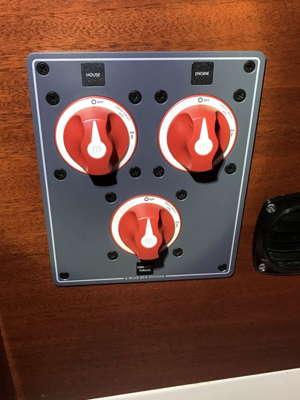
I have installed a new "OFF 1 Both 2" master switch and identified which heavy cable goes to which battery and the starter and replaced them with new.
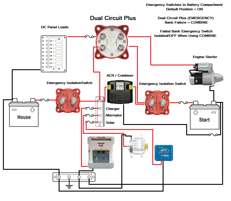
I have not installed an inverter, combiner, battery monitor or controller yet and won't until next Spring when I buy a new panel. Then I get to do all the fancy stuff mentioned in this thread.
For now I just want to finish reconnecting the job as described above.
So...
I've got a red, 10 ga. wire going from the Positive side of the panel to the Master switch connection position "C" (along with the 2/0 starter cable), and a black, 10 ga. wire (was originally white) attached to the engine (Main Ground ?) going to the ???? (Not sure).
I'd like some expertise before I screw up something important like the alternator, the boat or Me!
Thanks in advance.
G
 
Last edited:
Sep 28, 2008
922
Canadian Sailcraft CS27 Victoria B.C.
If your positive is 2/0 your negative should be the same size going to the engine block. 10 ga doesn't cut it.

10 ga is light for panel feed as well. I would use a heavier wire to feed the panel. 8 ga minimum, depending on length.
 
Oct 22, 2014
20,993
CAL 35 Cruiser #21 moored EVERETT WA
GG. The 2 wires that are 10 gauge. (1 pos and 1 neg). Are these coming from the alternator?
 
May 27, 2004
1,964
Hunter 30_74-83 Ponce Inlet FL
Mitiempo & JSSailem, Thanks for the replies.

One red, heavy gauge wire goes from the Master Switch to the starter. The other two heavy, red wires go from the two batteries to the Master Switch positions 1 and 2.
There is one black, heavy gauge wire from the battery banks to the engine block, of course.

I mistakenly said "10 gauge" in the original post.
The two wires in question are:
1. The red, 8 gauge wire from the common battery switch connection "C", per the Master Switch wiring diagram and other generic diagrams found online, goes to ?! Fairly Sure!? the accessory circuit breaker panel brass strip.
2. The black, 8 gauge wire connects to the engine block, as a ground, and goes to ? not sure?.

Those are the questions.
 
Sep 28, 2008
922
Canadian Sailcraft CS27 Victoria B.C.
ggrizzard

Sounds like you have 2 grounding wires to the engine. There should only be one. The negatives from all batteries should go to a bus using heavy wire. There should be one heavy wire from the bus to the engine - best place is starter negative. All other negatives start from this bus. In other words the panel negative feed comes from the bus.
 
May 27, 2004
1,964
Hunter 30_74-83 Ponce Inlet FL
Yes, there are two ground wires, counting the heavy, black battery wire and the smaller single black (formerly white) wire, that has no bus bar to go to.
Remember, this is a 1979 vintage Cherubini Hunter, made long before the idea of bus bars, isolators, inverters, and the like in mass produced boats.

I know the small black wire did go to the engine block originally, because I only took it off two weeks ago and didn't forget that action that quickly. So this small black wire went somewhere before I screwed up and disconnected the panel wires and didn't label it.
But I've already spent a ton on the boat due to Hurricane Matthew damage and I can't shell out hundreds more for a new panel and associated electrical re-dos until next year. So, unless someone out there can help me put the wiring back to the original spec, I won't be sailing again until next spring.
 
Last edited:
May 27, 2004
1,964
Hunter 30_74-83 Ponce Inlet FL
There's only one heavy black, negative battery wire going to the engine. I see what you are suggesting with the bus bar reducing the number of wires to the engine. But, remember, I'm getting a new panel and other upgrades next year, so for now I'm just trying to get it wired up as original so that I can go sailing. And since our initial discussion, I have confirmed the 8 gauge black ground wire does go to the panel, as you suggested. And thanks for your responses.

As simple as 12 volt electrical systems appear on the surface, I seem to have stumbled on a myriad of options and recommendations from Maine Sail and Stu and others for the upgrades I should do. So much to think about... So little money!
G.
 
Jan 22, 2008
8,050
Beneteau 323 Annapolis MD
Point being, the engine should not act as a conductor of electricity from one wire over to another under normal conditions. Me, I have no trouble with attaching the CHASSIS GROUNDS of the inverter or whatever, though.
 
Sep 28, 2008
922
Canadian Sailcraft CS27 Victoria B.C.
Point being, the engine should not act as a conductor of electricity from one wire over to another under normal conditions. Me, I have no trouble with attaching the CHASSIS GROUNDS of the inverter or whatever, though.
I always wire chassis grounds to the DC negative bus. Only one wire and connection on the engine.
 
Oct 26, 2008
6,045
Catalina 320 Barnegat, NJ
There's only one heavy black, negative battery wire going to the engine. I see what you are suggesting with the bus bar reducing the number of wires to the engine. But, remember, I'm getting a new panel and other upgrades next year, so for now I'm just trying to get it wired up as original so that I can go sailing. And since our initial discussion, I have confirmed the 8 gauge black ground wire does go to the panel, as you suggested. And thanks for your responses.

As simple as 12 volt electrical systems appear on the surface, I seem to have stumbled on a myriad of options and recommendations from Maine Sail and Stu and others for the upgrades I should do. So much to think about... So little money!
G.
I would prefer to bring the negative wire from the panel back to the negative battery post rather than run it to the engine block. The neg battery posts are grounded to the engine with a 2/0 battery cable, right? That said, the suggestions to bring it (panel neg wire) back to a negative buss bar are obviously the way to go. You'll be using it regardless of what you purchase in the future so there really is no excuse not to do it this way as soon as possible. You would bring all your negative leads - from the battery posts and the panel and anything else that might be directly wired off the batteries - to a buss bar and use a 2/0 battery cable from the buss bar to the engine block for grounding.
I don't think there is any reason to place so much importance on the 'original spec'. They just do what is expedient, not necessarily what is right. The alternator on my new engine was wired to the starter positive post and had a chassis ground. I needed to modify it to bring the alternator positive back to the house bank and the negative back to a neg buss, otherwise I would have battery charging problems with the 'original spec'.
If you have a very simple set-up with just 2 batteries hooked up to a 1-2-B switch, you'll get by, but it doesn't hurt to start planning your system and wiring accordingly. I imagine your alternator is wired to the starter and grounded on the engine. If you don't have ACR, I suppose you just use your switch to direct the charging destination.
Are you repairing an AC system? Where does the ground for your AC system end? Should we assume you don't have an AC/DC charger set-up at this time?
 
Oct 22, 2014
20,993
CAL 35 Cruiser #21 moored EVERETT WA
But, remember, I'm getting a new panel and other upgrades next year, so for now I'm just trying to get it wired up as original so that I can go sailing.
GG
Understand your concern. I have been working through the same thinking. I decided to rebuild the project in three phases.
  • Phase one is to design and rebuild the battery box, charging systems and Positive/Negative connections located there. (Forced to address as an old charger died, alternator not showing any output, 2 batteries showing 0V. Needed to be addressed to use the boat) Had hoped to get one more season out of set up.
  • Phase two will be the wiring harness and DC/AC panels. They will be integrated with phase one.
  • Phase three will be cleanup and rebuild of loads around the boat (i.e. lighting, power outlets.)
Thinking in the term of phases lets you bite off a little at a time. Spread costs over time, and still enjoy your boat.
Previous Owners setup.
IMG_1059.JPG
New setup - Positive on right Negative on Left of image.
2017 BatteryBox.JPG
 
May 27, 2004
1,964
Hunter 30_74-83 Ponce Inlet FL
Scott, The importance is if I don't set it up for now as it was, I won't be sailing 'til next year!
JS, I kinda did your step three first because I had to buy lots of wire to repair damage in the mast wiring due to Matthew, so a little more wire didn't cost that much more. The AC side is intact and untouched for the moment. It will be replaced with new wire, outlets, smart shore plug and other goodies next year and will be installed professionally.

Group in General, I don't have a charger, an inverter, an ACR, or an updated alternator.
Those things and the new panel will come with next year's budget.
 
  • Like
Likes: jssailem
Oct 22, 2014
20,993
CAL 35 Cruiser #21 moored EVERETT WA
I was suggesting only spend funds (if available) on the busbars. You can use the same battery wires. You can route your alternator to the positive busbar (as in MaineSail's recommendation) and the next steps will flow.
  1. 2 - Mfg# 2127 MaxiBus 250A Busbar Consolidate Multiple Wires or Feed Multiple Circuits By: Blue Sea Systems Aprox $31.50 each
  2. 1 - Mfg# 2719 MaxiBus Insulating Cover for PN 2127 and 2128 Aprox $23.09 each
These prices are at a Seattle boat supply house. You may find them better prices on line (Amazon) ...
I had to add fuses and extend wires. I had the battery wires made up at the local chandler for about $6.50 a piece. But it cleaned up the battery box for less than I expected. I believe it is a lot safer as well.
 
Jan 19, 2010
1,169
Catalina 34 Casco Bay
A slightly different installation:

2 battery switches. Each has 1,2 and Both.

Bank and switch #1 is starting

Bank and switch #2 is house

Normal: Switch #1 to 1 Switch #2 to 2

Want to charge #2? Each switch set on BOTH

Need to start with house bank? Switch 1 set to 2, Switch 2 set to 1

What does all this accomplish? Long day on the water. Fridge, pressure water, ALL navigation ( including radar), elect head, ice maker draw down the house. IF not segregated and the engine is needed, the radar and chart plotter get dumped and need to reboot.
 
Feb 6, 1998
11,665
Canadian Sailcraft 36T Casco Bay, ME
A slightly different installation:

2 battery switches. Each has 1,2 and Both.

Bank and switch #1 is starting

Bank and switch #2 is house

Normal: Switch #1 to 1 Switch #2 to 2

Want to charge #2? Each switch set on BOTH

Need to start with house bank? Switch 1 set to 2, Switch 2 set to 1

What does all this accomplish? Long day on the water. Fridge, pressure water, ALL navigation ( including radar), elect head, ice maker draw down the house. IF not segregated and the engine is needed, the radar and chart plotter get dumped and need to reboot.
There is really no need for two 1/2/B switches as it becomes quite confusing, especially if there is no legend placard close by. A typical house bank on a 34 footer, that has refrigeration, should easily start the engine at 50% SoC without dropping out electronics. If it can't then the batteries are getting long in the tooth or there are wiring issues.

If that is the case, and you don't want to address wiring or batteries, a simple ON/OFF can be added to the 1/2/B or two simple ON/OFF's with an emergency parallel switch is all that is necessary.


A dual circuit plus switch with two hidden ON/OFF's also makes for a neat clean install.


We have numerous power boat customers that have dual 1/2/B switches from the factory and to say they are a nightmare for the owner to comprehend would be an understatement.
 
Jan 19, 2010
1,169
Catalina 34 Casco Bay
There is really no need for two 1/2/B switches as it becomes quite confusing, especially if there is no legend placard close by. A typical house bank on a 34 footer, that has refrigeration, should easily start the engine at 50% SoC without dropping out electronics. If it can't then the batteries are getting long in the tooth or there are wiring issues.

If that is the case, and you don't want to address wiring or batteries, a simple ON/OFF can be added to the 1/2/B or two simple ON/OFF's with an emergency parallel switch is all that is necessary.


A dual circuit plus switch with two hidden ON/OFF's also makes for a neat clean install.


We have numerous power boat customers that have dual 1/2/B switches from the factory and to say they are a nightmare for the owner to comprehend would be an understatement.
Barely had room to add the extra switch. A 3 switch set up would not have fit into the area...
 
Feb 6, 1998
11,665
Canadian Sailcraft 36T Casco Bay, ME
Barely had room to add the extra switch. A 3 switch set up would not have fit into the area...

With the Dual Circuit Plus drawing above it is one switch in the panel and one emergency isolation switch near each battery, out of sight of vessel occupants. Standard use is one switch ON & OFF.... In an emergency you turn off the battery compartment switch to the bad bank and turn the main switch to "combine":...
 
Jan 19, 2010
1,169
Catalina 34 Casco Bay
With the Dual Circuit Plus drawing above it is one switch in the panel and one emergency isolation switch near each battery, out of sight of vessel occupants. Standard use is one switch ON & OFF.... In an emergency you turn off the battery compartment switch to the bad bank and turn the main switch to "combine":...
Does "combine" take the bad bank out of play or join both banks together?
 
Oct 26, 2008
6,045
Catalina 320 Barnegat, NJ
"Combine" does exactly that - combine. The purpose of the on-off switches ahead of the DCP is to take a bad bank out of service so that Combine just utilizes the good bank. The reason I like the DCP switch is because it provides service to 2 banks in isolation simultaneously (4 posts - 2 poles). The 1-2-Both switch doesn't have that capability. You can only have one bank or the other on at a time - unless you switch to "Both", which is not preferred.