Strange Electrical Issue

Nov 18, 2010
2,441
Catalina 310 Hingham, MA
This issue has been going on since we’ve owned our Catalina 310 but I never really thought about it until recently.

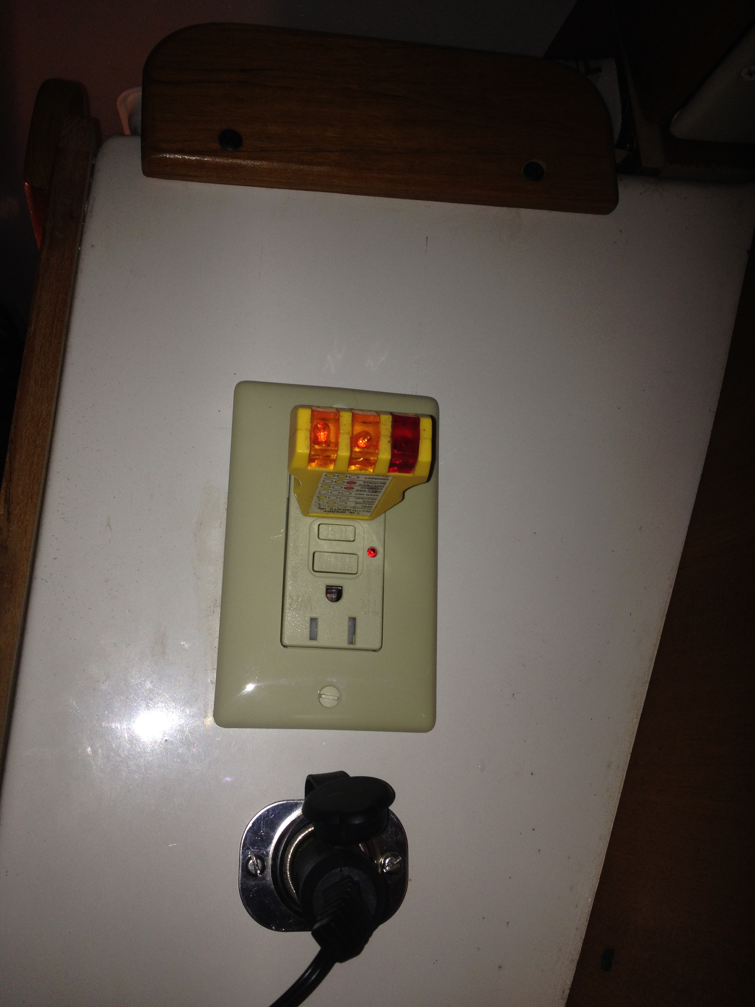
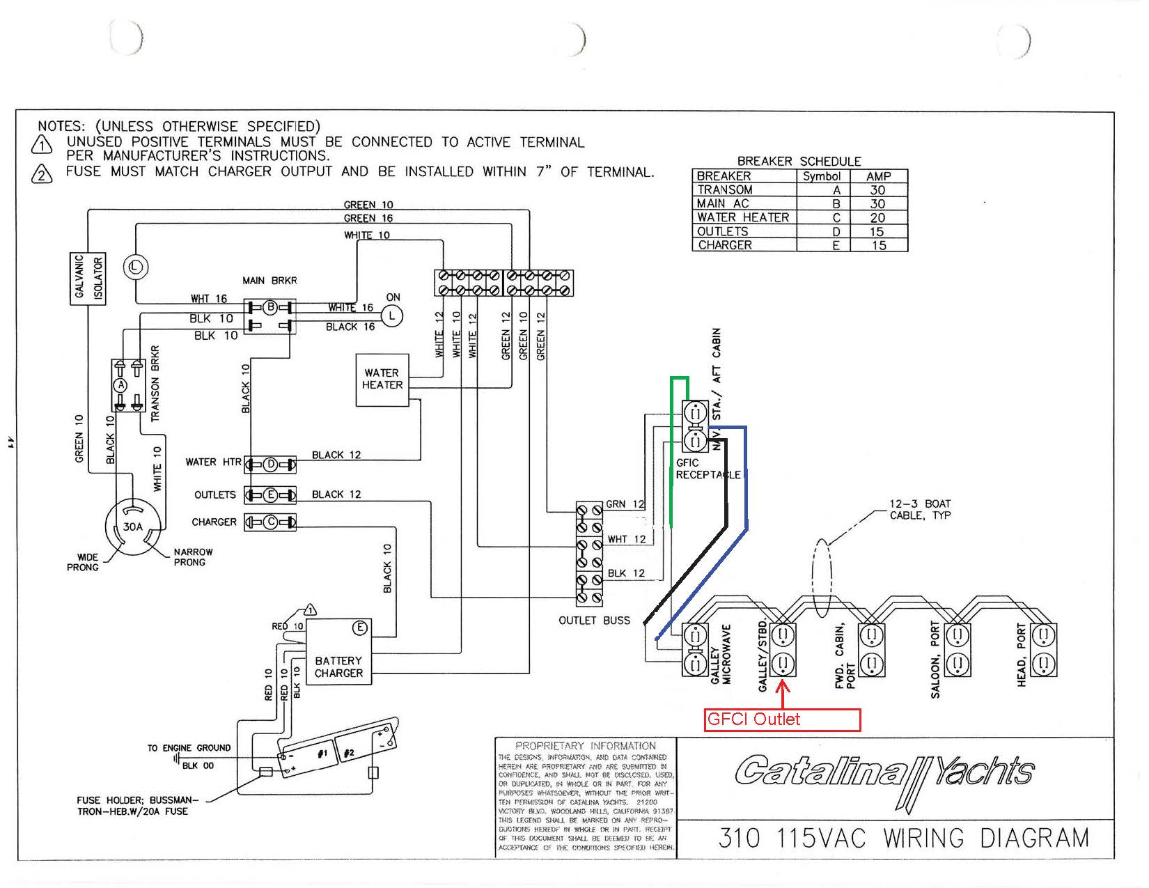
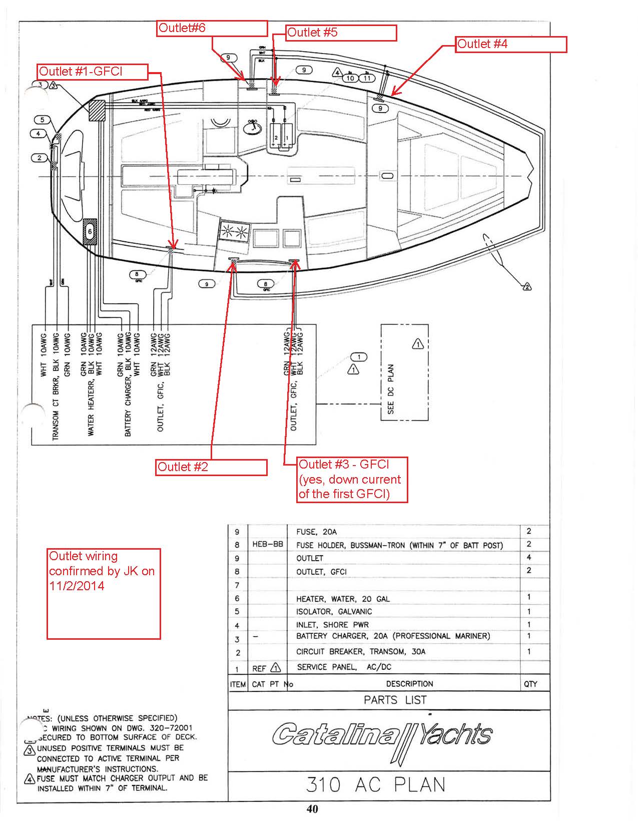
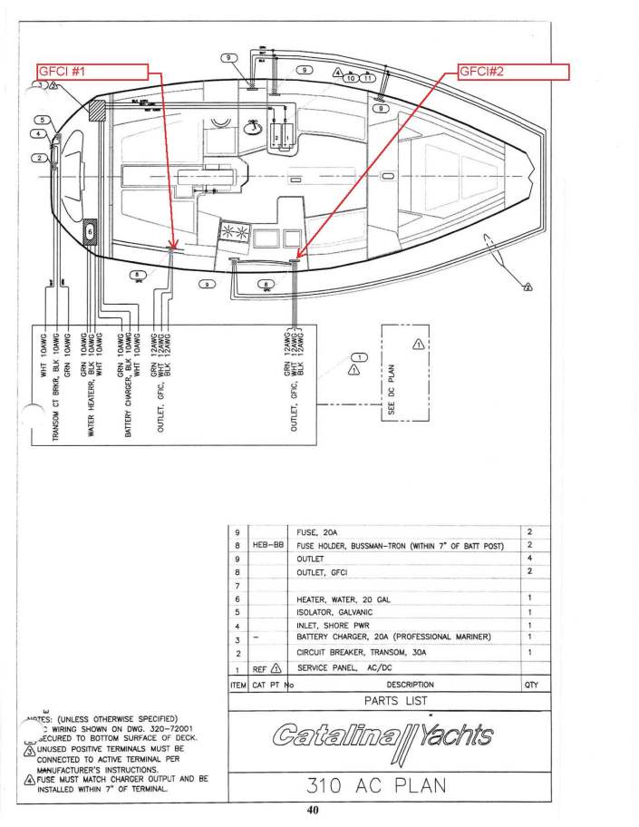
We have two GFCI Outlets on the boat. GFCI Outlet #1 is at the navigation station and according to the wiring diagram should be the only outlet connected on that run. GFCI #2 is at the galley counter and should be the first in the line protecting the rest of the outlets on the boat.


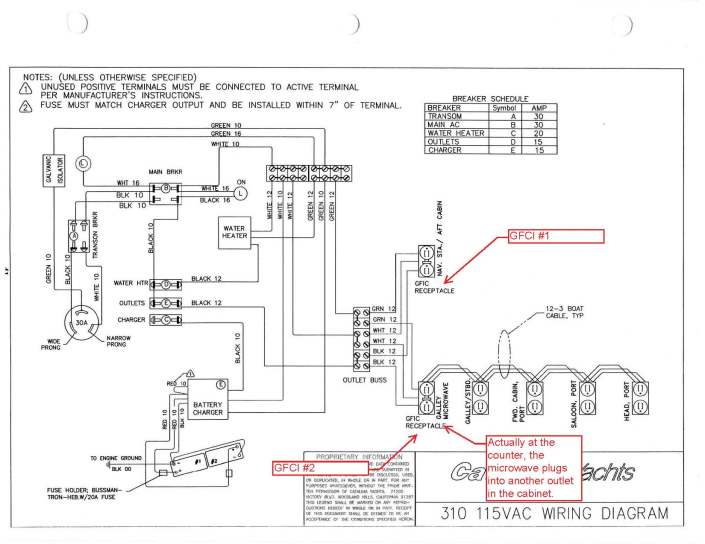
Now here is where things get a little strange. When GFCI #2 is tripped, no problem. All of the other outlets are tripped down the line. But when GFCI #1 get’s tripped, it also trips all of the outlets, including GFCI #2. Further, the bottom outlet on GFCI #1 will continue to work when tripped.

Looking at the wiring diagram there is no reason why tripping GFCI #1 should disable the outlets on the leg for GFCI #2. But it happens.

Also, I don’t like the fact that the bottom outlet on GFCI #1 continues to work when tripped.

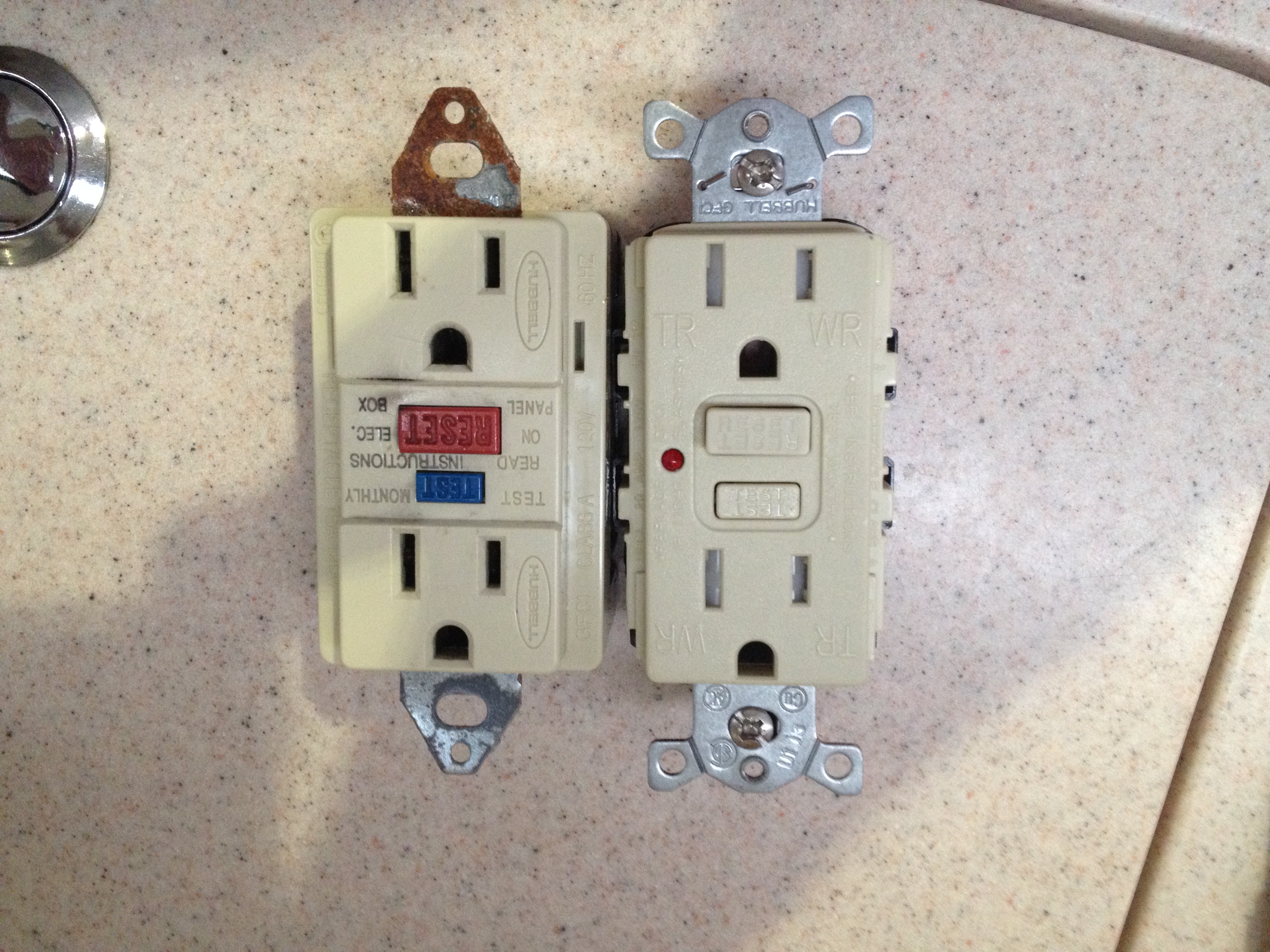
My plan is to verify the wiring is as per the diagram. I suspect that somehow the factory wired the GFCI outlets different than shown. I am also going to replace both GFCI outlets, which brings up another question.

Is there any difference between a marine GFCI outlet and a standard GFCI outlet you get in the box store?

I looked at the GFCI outlets at Fisheries Supply, which are made by Marinco. I read the info on their webpage and they call it a “marine electrical duplex GFCI receptacle” but I can’t find anything that actually makes it marine. What is the difference between the Marinco and the Leviton Smart Lock Pro 15 amp weather resistant outlet? The Leviton is less than half the price and I can go pick it up and skip the shipping charge?

I am going to cross post this on the C310 Forum.

Thanks for any help you can provide.

Jesse
 
Mar 20, 2012
3,983
Cal 34-III, MacGregor 25 Salem, Oregon
the very first thing i would do is pull #1 out and replace it.... all gfci outlets are not the same quality and ive seen so many fail in various ways that i go to the outlet that shows the slightest sign of problems and replace it.... and almost always solves all the issues.

if #1 is tripping yet one hole is still hot, it definitely has an internal problem.... and because of the failure there, it could be back feeding and tripping the other leg,
because it takes less to trip the gfci than it does to trip the main circuit breakers.

I replaced all my receptacles with gfci outlets and wired them independent of one another... otherwise the problem can be anywhere along the hot leg and you cant tell where the problem is... if the hot leg itself has a problem, it will trip the circuit breaker on that leg.
 
Nov 14, 2013
200
Catalina 50 Seattle
Also, no need for the Marinco GFCI. The only issue I've found with the standard Levitons, Coopers, etc is that they're designed for use with solid copper wire so they stake the threads of the screws to keep them captive in the outlet terminals. If you're using ring terminals on your wire, and you should, you need to pull the screws completely out to fasten the rings to the outlet. If you crank on the screws, you can strip the screw and/or terminal threads. Best to unscrew until they get a bit tight, screw them back in a bit before unscrewing further. Lather, rinse, repeat.
 
Feb 6, 1998
11,667
Canadian Sailcraft 36T Casco Bay, ME
Double check the wiring then replace the GFCI's anyway. Catalina has been known to not follow their own diagrams.. :doh:

In the marine environment 5-8 years is about as good as it gets... Remember these devices trip on a 5mA imbalance between hot & neutral and the tripping action may be in the feed to the branch breakers meaning both should trip at the same time if both are loaded when the imbalance occurs.. 5mA is just 0.005A of a difference between white and black wires. This level of mA leakage is really easy to accomplish with boat and marina wiring...;)

Just be sure that when buying GFCI's they meet UL 943... This does not require them to be a "marine" GFCI but does mean you're not buying a bottom of the barrel cheap GFCI either and you're buying a decent "class A" GFCI..

Look for a "WR" rated UL 943 GFCI and you'll be doing pretty well.. I also use WR UL 943 GFCI's at home (Legrand) and they outlast the cheapies by about 10:1.

Hubbell & Legrand/Pass & Seymour make UL 943 GFCI's I know to hold up pretty well in the marine environment but Leviton & others make them also. Leviton in the electrical world has the nickname Levicrap so be aware of that.

It can be tough to find a good quality WR UL 943/Class A GFCI at other than an electrical supply house, but they can be found.. I often use the Hubbell GF5252MWA which is white and stocked at one of my local electrical wholesalers. They are a decent GFCI for the money and hold up better than what you will find at a home center..

Be aware that Marinco simply sticks a WR Leviton GFCI into a Marinco box, calls it "marine", and charges you 6X the real going rate....:doh:

Now if you really want a good quality "marine duty" GFCI spend the money on a hospital grade GFCI such as the Hubbell GFR8200WTR (the 20A version is the 8300). These are WR rated (tamper-proof too) but nickel plated internally to resist corrosion. It is what I have on my own boat. Grab your ankles though because a hospital spec GFCI will run you about $90.00..... I grabbed mine in the scratch & dent bin at my local wholesaler for $20.00 each because I knew what they were....:doh: The Legrand hospital GFCI is great too and slightly less money depending on which model..

Good quality GFCI's, that tend to last longer on boats, come from Legrand/Pass & Seymour & Hubbell. It has been my experience that they out last the others in the marine world. Cooper Industries does okay too..
 
Jan 1, 2006
7,063
Slickcraft 26 Sailfish
As usual, thanks Mainesail. I now know why I have had to call my electrician back to replace our outdoor GFI's almost yearly. Next time I'll buy the GFI and he can put it in.
 
Nov 18, 2010
2,441
Catalina 310 Hingham, MA
Thanks MaineSail.

Struck out at 3 local electric supply houses on finding any of the brands you suggested. Found a couple online so I will be ordering some tomorrow.
 
Sep 15, 2009
6,243
S2 9.2a Fairhope Al
Thanks MaineSail.

Struck out at 3 local electric supply houses on finding any of the brands you suggested. Found a couple online so I will be ordering some tomorrow.

try Lowes in Hingham ma they will have cooper or Home depot they should have pass and semor
 
Dec 13, 2010
123
Hake 32RK Red Bank
I'd check to make sure that GFCI circuit 2 is not fed off the load side of GFCI 1...also check that the GFCI outlet 1 is properly wired with source on the source terminals not on the load terminals
 
May 7, 2014
2
Beneteau 461 Oceanis Charleston SC
Centerline it sounds like GFCI #1 is improperly wired. The A/C Power goes from one breaker on you panel and the black wire should go straight to the hot side of GFCI #1 AND GFCI #2. The hot wire is running to GFCI #1 and through it and to GFCI #2. If you make sure the hot wire, is direct to both GFCI #1 and #2 (sorry I can't draw this out for you) you will stop this problem.
 
Nov 18, 2010
2,441
Catalina 310 Hingham, MA
I ordered the new GFCI outlets. I went with the Hubbell GFTR 15: http://www.hubbellcatalog.com/wiring/section-h-datasheet.asp?FAM=Ground_Fault&PN=GFTR15

It's a commercial grade, tamper resistant, weather resistant, UL 943 Class A GFCI receptacle. It is not hospital grade. I couldn't bring myself to spend that money given our current plans.

Cost wise, I got them on amazon for $10.99 each plus shipping. I could have got them Prime for $12.84 each (free shipping) but the shipping time was 3-5 weeks. http://www.amazon.com/gp/product/B003AXLBAM/ref=ox_sc_act_title_1?ie=UTF8&psc=1&smid=ATVPDKIKX0DER
 
Dec 3, 2013
169
HUNTER 29.5 PORT CHARLOTTE FL
Your boat wiring diagram is correct. Each GFCI receptacle is wired independently.

Good deal finding the ones you need.
 
Nov 18, 2010
2,441
Catalina 310 Hingham, MA
Yesterday I worked on this issue and here is what I found.

I started with the outlet in the galley. This one was easily accessible and the wiring was as expected.


Existing Wiring

Old Outlet on right (Hubbell Class A UL 943). New Outlet on left (notice the TR and WR)

I completed the change on the first outlet without an issues.

When I took out the second outlet I found an issue. According to the wiring diagram provided by Catalina, this should have been a single leg outlet with only a feed line connected to the top of the outlet and nothing connected to the bottom, load side. Well it was connected on both sides. I tried to look around and figure out exactly how everything was run. However, all of the wires were bundled in wire loom and I couldn’t follow it easily. It’s a little cool out and the temp in the cabin had dipped below 55 degrees so I decided to just put the new outlet in and then figure out how the wires were run.

I re-energized the outlets and checked to make sure I wired everything correctly. I used an outlet tester to make sure I had the polarity and ground connected correctly.


I then went through all the outlets and figured out what order they were wired and what the GFCI’s affected. Here is a revised wiring diagram based on what I found.


So all 6 outlets are on a single leg of outlets and the 1st and 3rd outlets in line are GFCI. This is incorrect wiring and probably responsible for part of the strange issue I was having. At the very least it’s a redundant GFCI.

My plan is to split the outlets into two legs. I think I will have outlets #1 and #2 on leg one and outlets #3 – #6 on the other leg. This would mean running a new 12-3 wire from the electric panel to that outlet. And then disconnecting the wires that run from outlet #2 to outlet #3. I am not a big fan of keeping unused wires in place so I will remove the old wires.

But now I am wondering if this is necessary. All the outlets are fed by the single 30 amp breaker. If I split the legs, both legs would still be fed by the 30 amp breaker. So is there any benefit from separating the legs?

If not, I could just remove the second GFCI outlet and replace it with a standard outlet. I could then save the GFCI outlet for next time I need to replace GFCI outlet #1.

After replacing the outlets I ran heaters, electric tea kettle, microwave, iron and dehumidifier at various times and levels and didn’t have any of the issues I was having before replacing the outlets. I did pop the outlet breaker at the panel once when I ran the heater on high with the microwave by mistake.
 
Jan 22, 2008
8,050
Beneteau 323 Annapolis MD
First and worst, is the 30-amp breaker. You'd have to have #10 wire to justify a 30. Even then, the recepticals would be wrong. To assume you have either 14 or 12 wire, you need a 15 or 20-amp breaker. Best bet, if you can swing it, is have two breakers, and wire each GFCI to it's own breaker. /// My B323 OEM wire had two wires on one 20 breaker, limiting the 30-amp shore power to 20 amps of appliances. I move one wire to a new breaker, then could utilize all 30 amps if needed.
 
Nov 18, 2010
2,441
Catalina 310 Hingham, MA
First and worst, is the 30-amp breaker. You'd have to have #10 wire to justify a 30. Even then, the recepticals would be wrong. To assume you have either 14 or 12 wire, you need a 15 or 20-amp breaker. Best bet, if you can swing it, is have two breakers, and wire each GFCI to it's own breaker. /// My B323 OEM wire had two wires on one 20 breaker, limiting the 30-amp shore power to 20 amps of appliances. I move one wire to a new breaker, then could utilize all 30 amps if needed.
It could be that the outlet breaker is 20 amp. (just saw where its marked, its a 15 amp breaker on the outlets) It's not labeled in the wiring diagrams. I assumed 30 amp because that is what the main breaker is and what the shore power is providing. But I don't think I could ever get the full 30 amps out of this one cable because the battery charger and water heater will also run on this circuit.

The outlets are wired with 12 gauge wires and the outlets themselves are 15 amp with 20 amp flow thru.

But if its a 20 amp breaker for the outlets, is there any real benefit to having a couple of outlet legs versus one outlet leg?
 
Jan 22, 2008
8,050
Beneteau 323 Annapolis MD
(just saw where its marked, its a 15 amp breaker on the outlets) ... I don't think I could ever get the full 30 amps out of this one cable because the battery charger and water heater will also run on this circuit.

>>>You can always shut either the charger or WH off to make use of the outlets as needed.<<<

The outlets are wired with 12 gauge wires and the outlets themselves are 15 amp with 20 amp flow thru.

>>>>If your wiring is 12, I would have gone with the new outlets a 20, and change the breaker to a 20.<<<<

But if its a 20 amp breaker for the outlets, is there any real benefit to having a couple of outlet legs versus one outlet leg?

>>> Only as said in my #14 post. If the facitites are there, why not make use of them? Better to have the extra capacity and not need it than to need it and not have it available. I assume the outlet where you plug in the microwave is something of a gang box? If that's the case, that's alot of wires, depending on box size. <<<
 
Sep 28, 2008
922
Canadian Sailcraft CS27 Victoria B.C.
The individual circuits are most often 15 amp, but can be 20 with a 20 amp rated outlet or GFCI. If 15 amp they are wired with 14 awg, if 20 amp 12 awg.

The only outlet on a 20 amp breaker should be one rated for 20 amps, even if wired with 12 awg.

The reason for less outlets per circuit is so you do not overload an individual circuit. For example on a 15 amp circuit there could be a heater and a microwave each plugged in. Usually only one can be on at one time, even though the 30 amp dockside supply will handle their combined load. With these 2 items on separate circuits there is no problem running both at the same time as long as the dock supply can handle it.

I live aboard and have a panel with the 30 amp double pole main breaker and 6 circuits of 15 amps each. They are a hard wired battery charger, a hard wired 1000 watt heater, and 4 duplex outlets. Each duplex is a GFCI. I only concern myself with the total amperage and not with individual circuits and haven't popped any of my breakers in 5 years.

When a manufacturer puts multiple outlets (or all outlets) on a single breaker it is for cost reasons, not practical reasons.
 
Nov 18, 2010
2,441
Catalina 310 Hingham, MA
So I follow what Ron and Mitiempo have said and this brings me back to one of my questions.

I have 6 outlets on one 15 amp breaker. The 1st and 3rd outlets are GFCI. Which means the 3rd outlet being GFCI is redundant and not needed. I should just replace that outlet with a standard outlet and leave all 6 on a single leg because there is no benefit to having two separate legs going to the same 15 amp breaker.

If I wanted to get some additional power usage I should add a second 15 amp breaker and split the outlets between the two 15 amp breakers.

Am I correct?
 
Feb 26, 2004
22,770
Catalina 34 224 Maple Bay, BC, Canada
So I follow what Ron and Mitiempo have said and this brings me back to one of my questions.

I have 6 outlets on one 15 amp breaker. The 1st and 3rd outlets are GFCI. Which means the 3rd outlet being GFCI is redundant and not needed. I should just replace that outlet with a standard outlet and leave all 6 on a single leg because there is no benefit to having two separate legs going to the same 15 amp breaker.

If I wanted to get some additional power usage I should add a second 15 amp breaker and split the outlets between the two 15 amp breakers.

Am I correct?
Smitty, sounds good. Our C34s have one loop around the boat for three of the five receptacles, the two others are on a separate loop. Most of us with the older Mark I boats have added GFCIs in the head, and the first receptacle on the other loop.

I don't understand the "rant" at all. While he's right, it surely doesn't apply to you or this discussion. He also seems to be new to this forum, 5 total posts. Wait til he gets to know us! :)
 
Nov 14, 2013
200
Catalina 50 Seattle
Smitty, sounds good. Our C34s have one loop around the boat for three of the five receptacles, the two others are on a separate loop. Most of us with the older Mark I boats have added GFCIs in the head, and the first receptacle on the other loop.

I don't understand the "rant" at all. While he's right, it surely doesn't apply to you or this discussion. He also seems to be new to this forum, 5 total posts. Wait til he gets to know us! :)
And then there's the whole Macgregor issue... :D

*ducking!*