O’day 25 Outboard Wedge Replacement Project with Question to the Forum

Aug 25, 2014
21
O'Day 25CB Claremore, OK, Redbud Marina
I'm working on the new boat. She's a 1928 Oday 25:
1982 O'Day 25.JPG

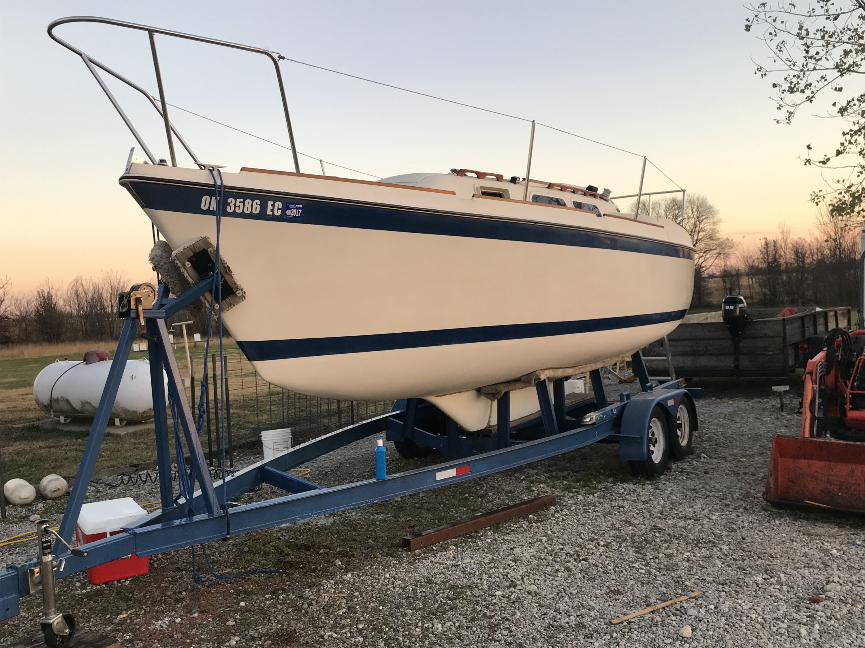
The previous owner of my 1982 25 was kind enough to replace her outboard with a brand new 9.9hp mercury. Unfortunately the new motors weight exceeds the capacity of her original Garelick mount. I purchased a new mount (model 71091) to better stabilize the outboard and support it’s weight.
Merc 9.9 on mount.JPG

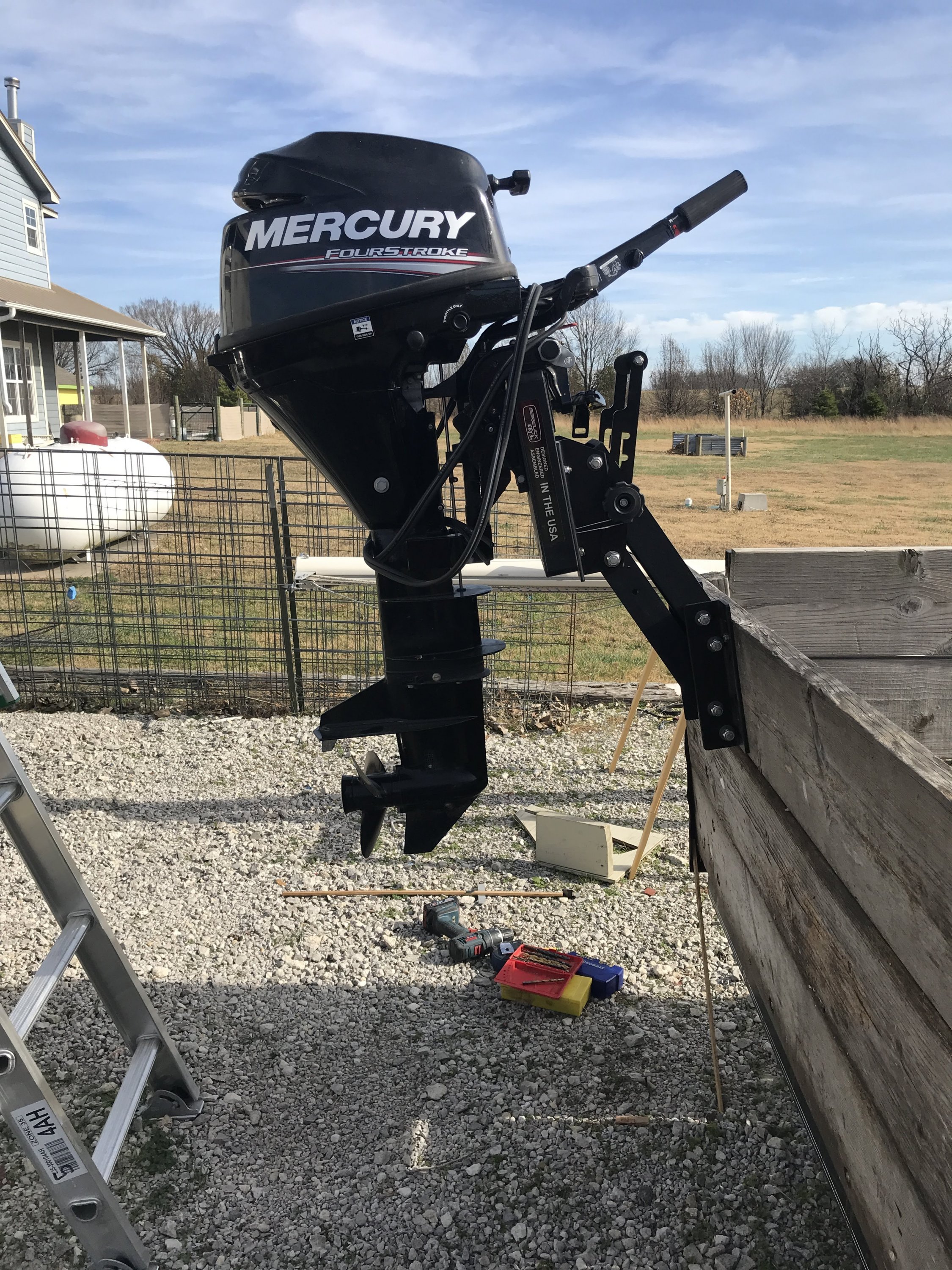
Photo [Outboard mounted on new Easy Lift, bolted to rear of flatbed]
Garelick Easy-lift.JPG

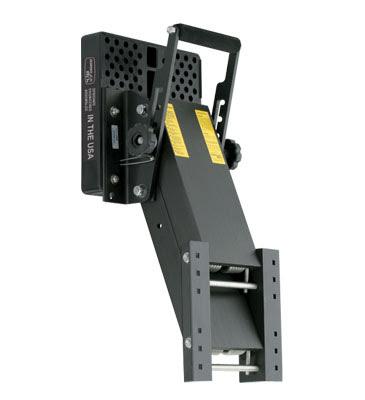
Photo [Garelick 71091]

The 25 has a reverse raked transom which requires a wedge to correct the angle of the outboard prop. The original O'day wedge has too small a footprint for the new Garelick mount with its 10"X10" bracket. I've removed the original part and molded the new fiberglass/gelcoat shell for the replacement.

Transom wedge mock-up.JPG

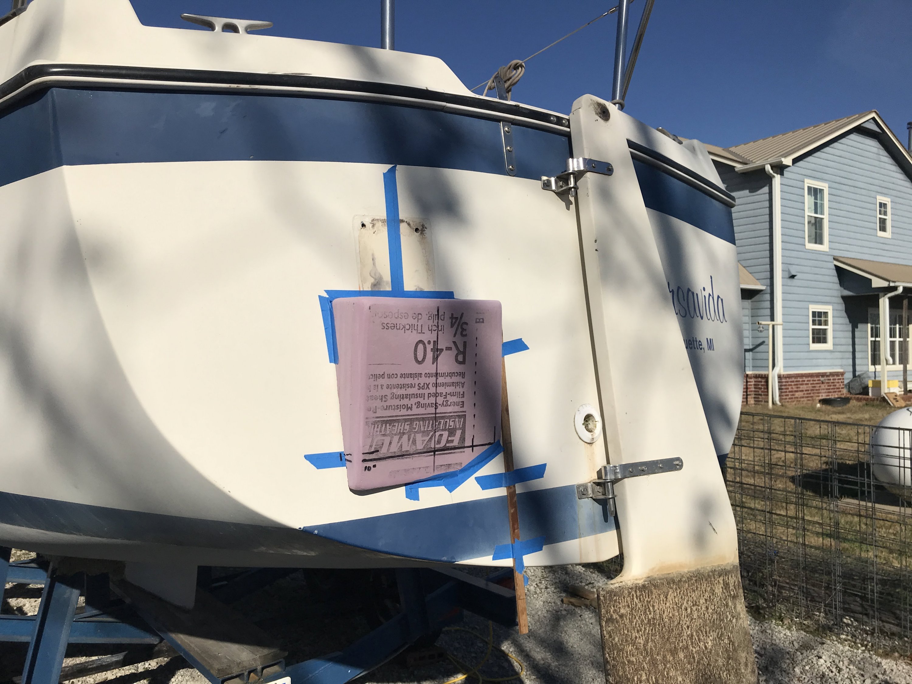
Photo [Foam mock -up of replacement wedge above. Its only got a few degrees of positive angle. I'm trying to strike a balance between prop angle in the water and lifting angle to get the outboard up. The old bracket was darn near impossible to lift at all. Had to tilt the outboard to get the lower unit out of the water and left the undersized bracket down.]
Replacement Wedge with mold.JPG

Photo [The yellow mold I made for the new wedge next to the final shell with it's pretty gel coat. FYI, I think I found a good recipe for tinting gel coat to match O'day off white. Holler at me if you need it.]
Surface wedge shell.JPG

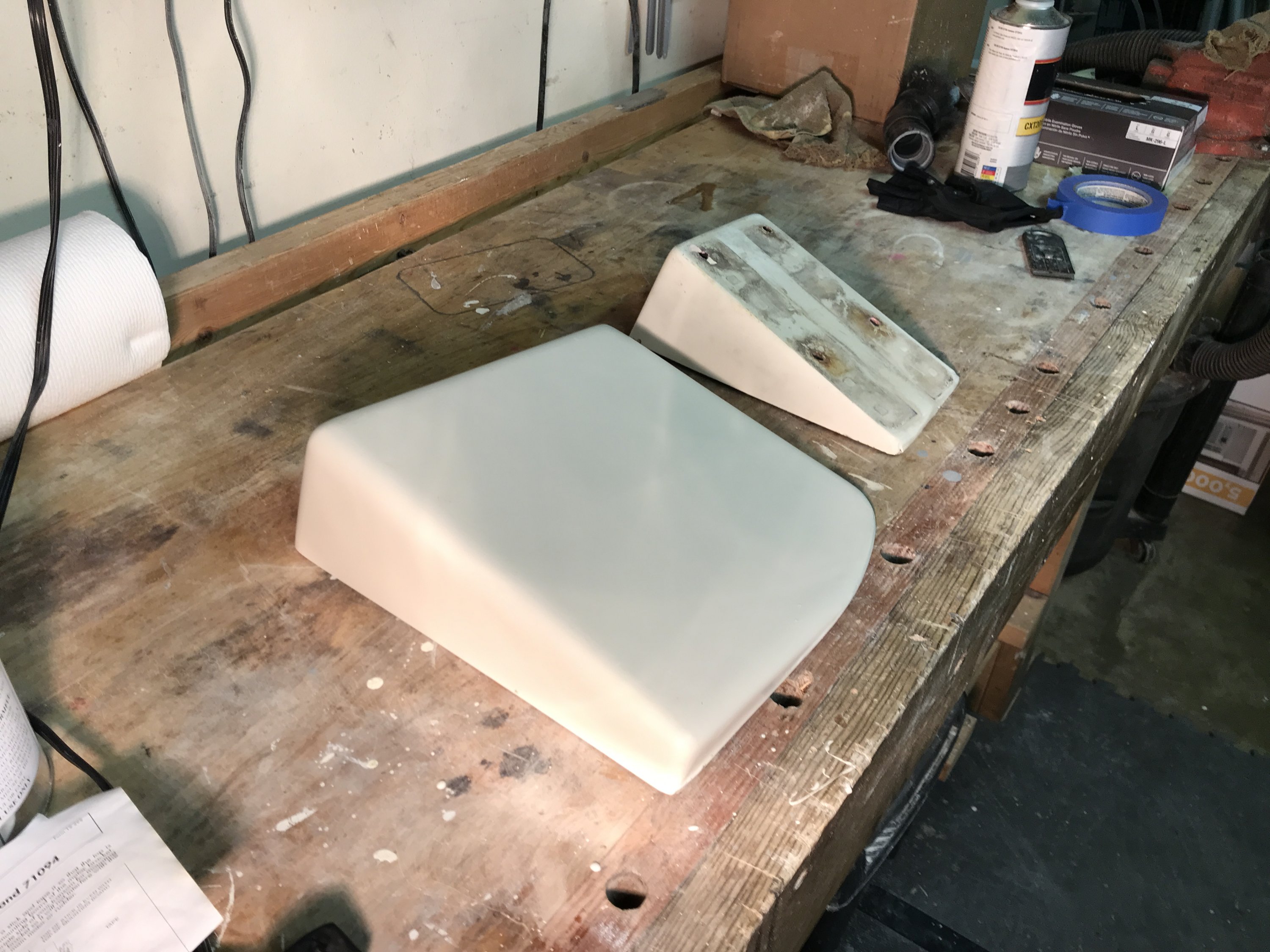
Photo [The new wedge next to the old.]
Reverse of new and old wedges.JPG

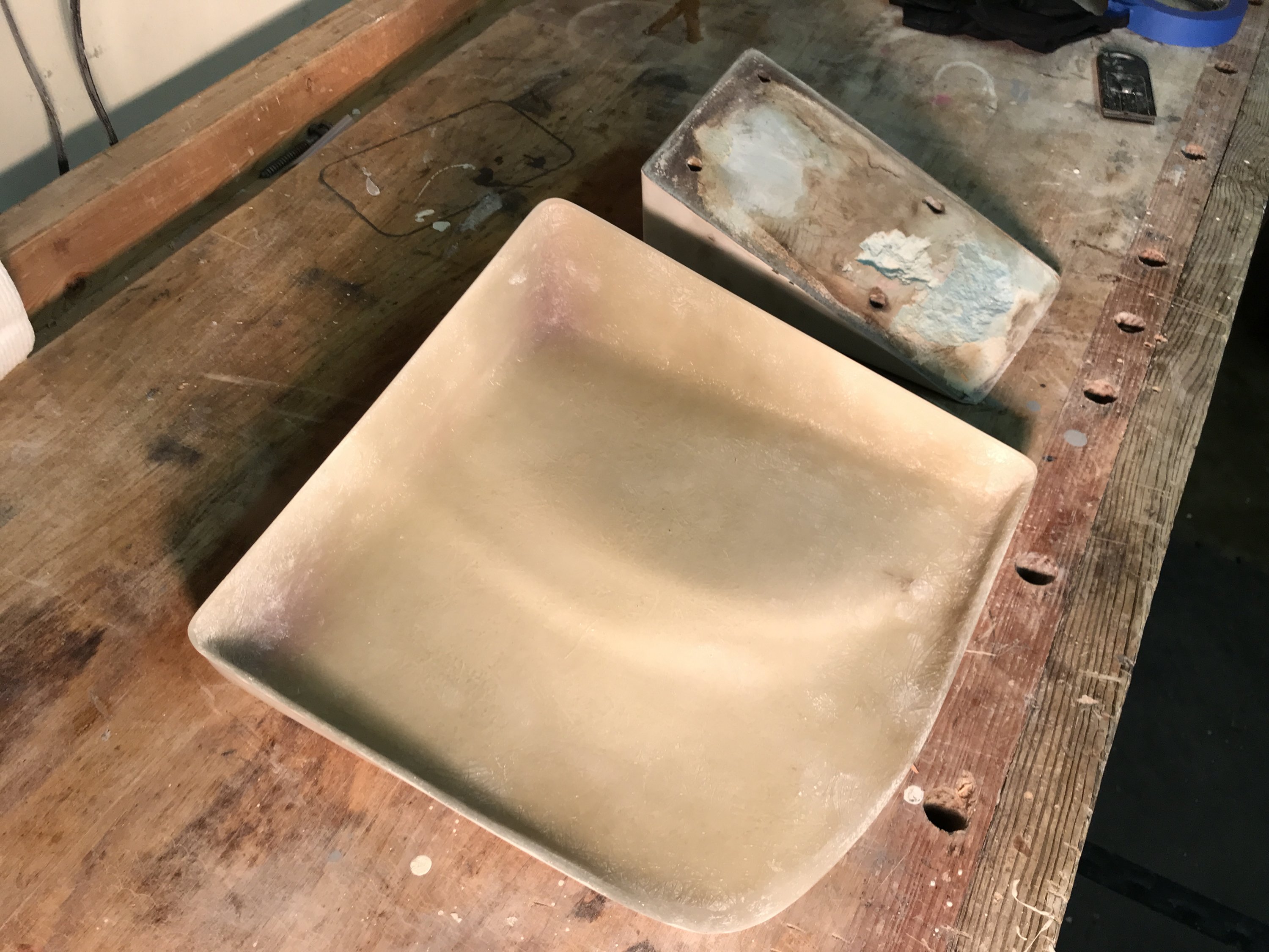
PPhoto [Inside view of the new wedge. Not the rubber filler on the inside of the original unit. I had a better picture of the inside of the old one, but Apple changed it's photo format just to mess with me and I can't post it on the forum.]

I'm at a crossroads regarding the filler material for the new wedge. The original was filled with some kind of mysterious hard rubber of unknown pedigree. Does anyone have any suggestions what this might be?

I've thought about filling with epoxy or poly resin but I'm already concerned with the weight of the motor/mount/wedge/transom reinforcement combo. I'm also concerned with the exotherm of such a large pour getting dangerous or ruining the shell... aaaaand epoxy ain't cheap in that kind of volume.

I've already cut and shaped some marine plywood that I could epoxy in, but I really don't like the idea of wood so close to the waterline. One point of moisture entry and the core will be rotten and all this hard work down the tubes.

Wood core.JPG

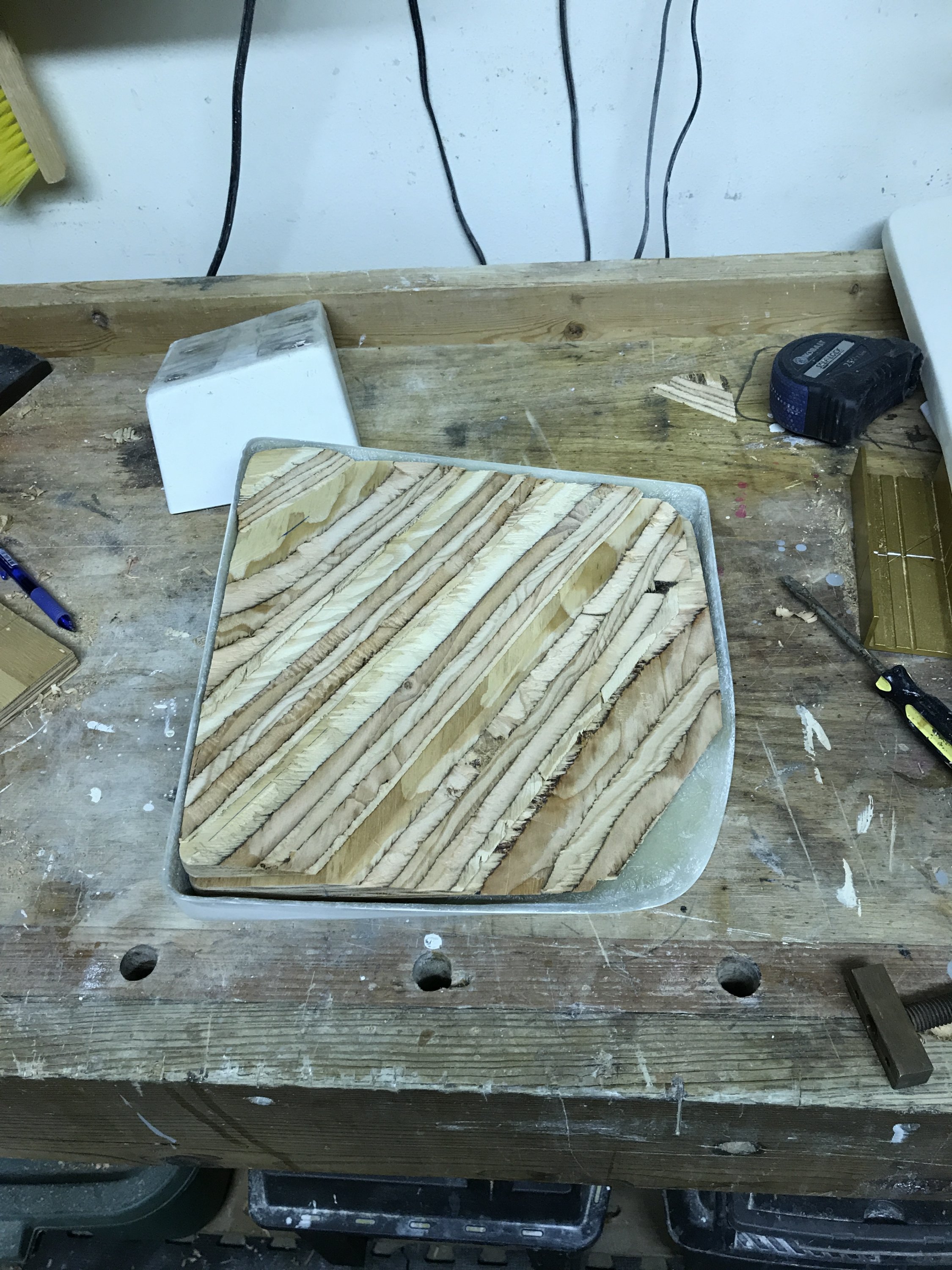
Photo [Yucky wood core option.]

There's a seller of gallons of RTV silicone online that has caught my attention. Any thoughts on using it as a filler rubber? Will silicone properly bond to the poly resin inside surface? If I go this route I'll test it in a sacrificial shell of the same material before committing to pouring into the actual wedge, but I'd love to hear what you have to say before I spend the money to have a gallon of silicone shipped to the house.

http://siliconedepot.com/premium-10...ckets-and-pails-available-in-multiple-colors/
 

JRT

.
Feb 14, 2017
2,048
Catalina 310 211 Lake Guntersville, AL
That looks amazingly sleek and professional! I'd add a solid fiberglass buildup or wood, silicone will have compression and cause cracking. Also since you are going through all this effort you will need to beef up the transom which I've seen others do with wood, aluminum plate or aluminum angle.

My wedge is just wood but seems it was sealed and holding up fine.
 
  • Like
Likes: 4father

Ward H

.
Nov 7, 2011
3,651
Catalina 30 Mk II Barnegat, NJ
I wouldn't use the silicone. I would be worried it was not dense enough to not compress when you tightened the mounting bolts.
I would go with the wood insert. Lay it into a bed of epoxy, fill the sides and coat the back. Then drill the correct size mounting holes from the front. Turn it over and drill the wood mounting holes over sized. Don't drill through the fiberglass shell when you do this. I would go 1/2 over size. Plug the fiberglass shell holes, fill the over sized holes in the wood with epoxy, then drill the epoxy filled holes to the correct size.
The water won't get to the wood and the epoxy will act as spacers.
 

Ward H

.
Nov 7, 2011
3,651
Catalina 30 Mk II Barnegat, NJ
I would check out G10 board for the backing plate. It is a compressed fiberglass board available from McMaster Carr as well as other places. I used it as a backing plate when I installed my boarding ladder.
 
  • Like
Likes: 4father
Aug 25, 2014
21
O'Day 25CB Claremore, OK, Redbud Marina
Thanks Ward and John. I just got a callback from the folks at Silicon Depot and they agreed with your assessments. The silicone will be too flexible for the application. Whats called for here is some kind of a rubber compound that pours as a liquid and sets up as a solid. Now if I could just figure out what that mysterious product is...

I'm starting to get more comfortable with the idea of lining the cavity of the wedge with the sheets of resin soaked plywood and burying them in a cabosil thickened bed of resin to create the core. I've done a considerable amount of deck core replacement projects in the past, Ward, and agree that potting the bolt holes with epoxy is definitely worthwhile. Although it's likely that the wood core will happen, I'm willing to wait a while to see if the hive mind has any other hard rubber suggestions.

I also agree with the suggestion of G10 for a backing plate. I've used it to make her winch and cleat backing plates already and have a sizable sheet waiting in the garage for use as a transom backing plate.
 
Jun 2, 2004
1,925
Oday Day Sailer Wareham, MA
I highly doubt that the original was filled with any "rubber" compound, I think it was a combo of wood and thickened resin/putty. If you are finding "rubber", I suspect that is just remnants of the original bedding compound used to seal the gap between the wedge and the hull.
 
May 31, 2004
858
Catalina 28 Branford
I "fixed" the wedge on my Oday 23 by scraping out some rotten core and replacing it with epoxy-saturated plywood. No problems in 10 years. Coincidentally, this summer, I had the same outboard/mount/wedge replacement issue as you do. Instead of building a new wedge to support the wider mount, I designed this "adapter" out of G10. Much easier and cheaper (at least for me).
 

Attachments

  • Like
Likes: JRT
Jan 22, 2008
9
Oday 25 Centerport , NY
I had the same problem with my 1976 OD25 when I decided to repower with a new Honda 9.9 electric(tilt) motor, and also needed a new wedge and OB bracket. Using the same Garelick OB bracket, I also cast a mold like you, but used a drawer from a cheap poly 3-dwr cabinet found at Target which matched my dimensions, after lots of research and shopping. Supporting it at an odd attitude while casting was “fun”, as I needed the top of the mold, which would be the backside (next to transom) to be level, since when pouring the resin into my wedge layup, I didn’t want it to overflow. The wedge just popped right out of the poly drawer when I finished the gel/roving/mat layup. The heat from curing didn’t really deform the poly mold to any critical degree. I then filled the wedge with epoxied random-shaped cuts of scrap plywood to provide multi-directional strength, and poured the resin over the wood. What I didn’t figure on was that the wood pieces floated in the resin! So I used wax paper weighted down by two bricks and did the filling in two stages 15 minutes apart that worked to herd all those little cats! Once cured, I filled the remaining voids with solid resin and had my wedge. I wanted about a half to three quarters inch of solid resin on the backside when finished. It was a matter of trial and error to then grind the backside to the compound curve shape to match the transom. Any slight edge chipping would be covered with the white silicone edge seal when installed. I obtained long SS carriage bolts on the web for mounting. I first drilled out the wedge, then marked the transom, drilled again, then backed it inside with plywood. During installation I sealed around all holes with silicone. Thankfully it all fit together and looks almost as professional as yours! No problems in 8 years; the Garelick bracket works well, and that Honda electric tilt is perfect to bring the motor up in the bracket-down position for sailing. Rather like retractable landing gear on a plane! Good luck!
 

ebsail

.
Nov 28, 2010
241
O day 25 Nyack. New York
I did the same job on my 25 with the same OB mount but made TWO wedges out of hardwood, one under each side of the bracket, and then epoxied them over with 2 layers of glass and then painted. Also drilled over sized for mounting bolts and filled with epoxy and then redrilled to keep holes impervious to water. I used butyl rubber tape under all bolts, and the stern to wedge, joints. I gave up on silicone years ago. Backing plates are 4 x 6 G10. Prior to doing this, I suspected that there was some rot in the transom, so I drilled a series of 3/8" hole holes in vertical lines (works better if you finish with a flat ended bit) from the inside of the transom (not through the outside glass) and epoxied in hardwood dowels, each dowel dipped in thickend epoxy before inserting. Now the transom is very rigid. We tested by hanging a 250 pounder on the bracket, and saw no bending or distortion. If I did this again, I'd use 1/2" dowel.
P.S We hung a 6 HP 4 cycle, extra long shaft sail drive Tohatsu on the bracket and it seems enough power for almost any normal situation. Even against a chop and wind. We're suprised by the performance.
 
Nov 7, 2016
38
O'Day 222 Paris Landing, TN
I have a 222 on the Tennessee river in Tennessee. I am interested in a 25 but would like to know what the cabin height is. I was wondering if you could measure yours the next chance you get. Thank you in advance...Randall
 
Aug 25, 2014
21
O'Day 25CB Claremore, OK, Redbud Marina
I know it's been a while, but I thought I'd do an update on the motor mount project. I went ahead and filled the inside of the shell with marine plywood set in a bed of epoxy. It took a considerable effort to cope the plywood to the right shape for the convex curve of the transom, but eventually I got something that worked.
IMG_5020.jpg

I smoothed the back of the final product with a hardened fairing compound composed primarily of cabosil with enough fairing compound to make it workable.
IMG_5061[1].jpg
IMG_5059[1].jpg
I then overdrilled all the mounting holes and filled them with solid epoxy to hopefully prevent future water ingress. The final product is bedded in 3M 5200 and throughbolted with backing plates.
IMG_5072[1].jpg
IMG_5076[1].jpg


Thanks everyone for your help and suggestions... enjoy!
IMG_5112[1].jpg
 

RKA

.
Jul 10, 2020
1
O'day 22 Marina
Hi all, I am experiencing a similar issue of bought an O'day 22 with a 9.8 4 stroke, it broke the current motor bracket, and I am wanting to replace it with a stronger motor mount bracket meant for 4 strokes. I currently am planning on doing something similar to HukilauMike by creating an adapter plate between the current wedge and new motor mount bracket. The holes on the wedge interfere with the edge of the new motor mount (inside edge where the bend is). HukilauMike did you countersink your bolts that go through your wedge in the G10? I have never worked with G10, but is that easy to do? Also what thickness of G10 is recommended for this?
 
May 31, 2004
858
Catalina 28 Branford
RKA: sorry for the late response; I don't look at this site much since I sold that boat last year. If I remember, I didn't need to countersink the bolts that hold the wedge to the transom as the motor mount didn't interfere with the heads.