Stray current in the water

JBP-PA

.
Apr 29, 2022
433
Jeanneau Tonic 23 Erie, PA
A friend of mine has found stray current coming from their boat into the water at the starboard engine. This is Lake Erie, so fresh water.
When shore power is not connected, there is no stray current.
When shore power IS connected but their main double breaker is off, there is still the stray current.
When the ground is disconnected from the starboard engine, the stray current goes away.
This suggests to me there is some leakage from hot or neutral to ground and there is a bad connection in the ground circuit somewhere on their boat or possibly in the shore power.

They asked me to help them find it because I am a gearhead. My plan is to take a good volt meter and test the voltage between various ground connections and a "real" ground, perhaps a lead in the water near the problem? Hopefully I'll find zero voltage until I pass the bad spot when I'll see microvoltage. Does this seem like a reasonable plan? Any other tips on how to nail down their problem?
 
Last edited:
Jan 11, 2014
11,766
Sabre 362 113 Fair Haven, NY
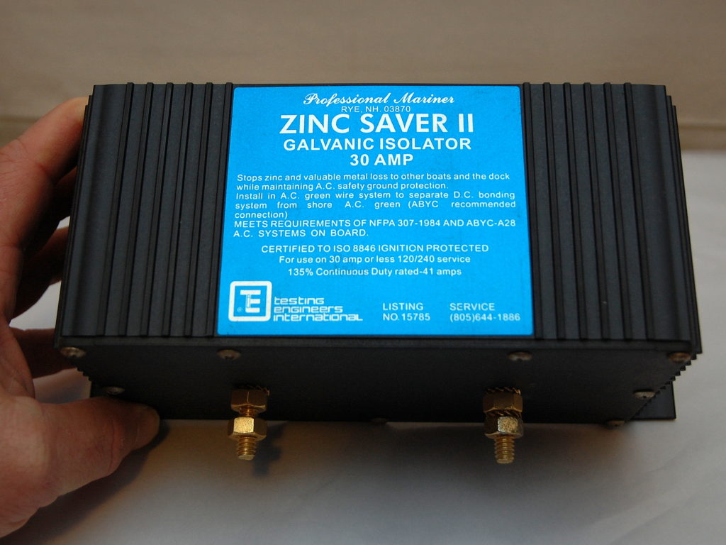
Do they have galvanic isolator installed? If they don't sounds like they need one.

Not connected to shore power and no stray current suggests the shore power ground is the culprit. How much voltage are they measuring?

I think the AC ground and DC- negative should only be connected at one place which could explain why there is no voltage leak from the port engine.

The problem may not be within their boat, except perhaps for the absence of a GI. The classic path for galvanic corrosion is 2 boats docked in the same marina and on shore power. A circuit is formed between 2 dissimilar metals through the water into the AC ground and on to the next boat with an AC ground connection. Interrupting the circuit with a Galvanic Isolator or an isolation transformer takes the boat out of the circuit.


jssailem

SBO Weather and Forecasting Forum Jim & John
Oct 22, 2014
21,499
CAL 35 Cruiser #21 moored EVERETT WA
If you want to test for stray current in the water, you should use a Corrosion Reference Electrode


For boat circuits a good digital volt meter will help provide the info regarding connections. Note it may be an AC source not just a DC source.
 

JBP-PA

.
Apr 29, 2022
433
Jeanneau Tonic 23 Erie, PA
Thanks, I'll ask those questions. BTW, the stray current was identified by the clubs groundskeeper who periodically checks around our boats for stray currents with some device.
 
  • Like
Likes: jssailem

jssailem

SBO Weather and Forecasting Forum Jim & John
Oct 22, 2014
21,499
CAL 35 Cruiser #21 moored EVERETT WA
I bought one of the reference electrodes. Helped to check my exposed metal thruhulls and shaft.

Additionally, when my diver slips beneath the surface, he’ll share it there is a tingle in the water.
 
  • Like
Likes: JBP-PA
Jan 1, 2006
7,196
Slickcraft 26 Sailfish
It would be remiss safety wise to not warn poster and readers to NOT swim around that boat and that marina. This has been covered in this forum many times but just in case a reader missed a post about this: As reminder in fresh water, the human body is a better conductor of electric current than the water. It takes surprisingly little current to interfere with cardiac rhythms.
 
Jan 11, 2014
11,766
Sabre 362 113 Fair Haven, NY
If the current is from galvanic action, it is a very low DC current and not particularly dangerous. However, if the stray current is AC then there is reason to be very concerned. DC current hurts boat, AC current kills people.

The first and most telling test is done with the boat on shore power. Check the voltage between the AC hot and the ground pin on any outlet. If the AC voltage reading is in the nominal range, 110v to 120v then either there is not galvanic isolator or it has failed. If there is current, then further testing really isn't necessary until a GI is installed.
 
  • Like
Likes: JBP-PA
Jun 17, 2022
85
Hunter 380 Comox BC
It is very possible that there is more than one issue. Electrical is not something that can be troubleshooted via the internet. I would offer that your fried should seriously consider hiring a competent marine electrician. There is also potential of incorrect wiring or damaged wiring at the pedestal, along with a faulty shore power cord.

An error in procedure with some of the tests that are required to troubleshoot can be deadly.

The test procedure would start at the pedestal, then the cord, then the boat. Some tests with and some without shore power connected. A 30A 120V connection in a marine environment can be deadly.
 
Last edited:
  • Like
Likes: JBP-PA

jssailem

SBO Weather and Forecasting Forum Jim & John
Oct 22, 2014
21,499
CAL 35 Cruiser #21 moored EVERETT WA
To provide clarity, my diver is a professional. He works commercial boats. He shares that diving to weld a part back on a commercial fishing boat is when he most often has experienced that tingle.

The issue is it can happen anywhere there is electricity and boats. Most often it is a poorly maintained power pedestal or an aged power boat with poor electrical connections. That said, It was an eye opener, last fall, when my boat filled with water. The damage to the batteries and the shorted cables was scary :yikes:.
I was on the phone with the marina maintenance crew (as I was driving to the boat) that was going to pump out my boat. I reminded to disconnect the boat from the power pedestal. The first reply was "What?" "Oh yeah! That would be a good idea." Of course by that time the batteries were dead.
Here is what I saw when looking at my battery connections. Talk about corrosion.
1721191596264.jpeg 1721191620680.jpeg 1721191661563.jpeg
 
  • Like
Likes: JBP-PA
Jan 11, 2014
11,766
Sabre 362 113 Fair Haven, NY
The cautions about electricity, water, and boats, is well taken. The most important piece of information that is needed is what kind, AC or DC, of current is present and how much voltage. If there is AC leaking then issue is most likely wiring somewhere along the line. The best protection against that is an ELCI which will break the circuit if more than a mAs is leaking.

If the current is low voltage DC, around 1 or 2 volts, then Galvanic current is the likely culprit. A galvanic isolator will solve the problem. I'm leaning towards this cause because there is no current leaking when disconnected from shore power and when connected with the breakers off there is still stray current. I'd be even more convinced if the breaker on the pedestal is turn off and the breaker on the boat is turned off and there is still stray current.
 
  • Like
Likes: JBP-PA

JBP-PA

.
Apr 29, 2022
433
Jeanneau Tonic 23 Erie, PA
The first and most telling test is done with the boat on shore power. Check the voltage between the AC hot and the ground pin on any outlet. If the AC voltage reading is in the nominal range, 110v to 120v then either there is not galvanic isolator or it has failed. If there is current, then further testing really isn't necessary until a GI is installed.
Can you explain this a bit more? The boat ground should be at the same potential as the shore ground within a volt or so or else the GI would conduct. But a voltmeter will indicate zero volts between hot and boat ground? Is this because a voltmeter does not induce enough current to trip the GI into conducting?
 
Jan 11, 2014
11,766
Sabre 362 113 Fair Haven, NY
Can you explain this a bit more? The boat ground should be at the same potential as the shore ground within a volt or so or else the GI would conduct. But a voltmeter will indicate zero volts between hot and boat ground? Is this because a voltmeter does not induce enough current to trip the GI into conducting?
First a voltmeter does not induce current in to the wire when measuring volts, it simply measures the volts in the wire between two points. When measuring resistance, the DVM uses a small current to measure the resistance. We're not interested in resistance at the moment.

Next, do not confuse AC ground and DC- they are very different.

When troubleshooting start with a list of symptoms and develop a likely hypothesis that can be tested. In this case the hypothesis is the problem is due to galvanic action through the AC ground wire. Why? because the symptoms point in that direction (see earlier post). Two assumptions I'm making is the stray current is DC and the AC ground is only connected to one engine. At this point I have no evidence to suggest these assumptions are false. We also don't know how the stray current was measured and how much stray current there is.

In house wiring the AC ground (green or bare wire) and the AC neutral (white wire) are connected at the breaker panel. So, if you measure the voltage between Hot and ground you will always see the nominal voltage, ~120vac. Because the neutral and ground are connected you should never see any voltage between them and if you measure the resistance there should be no resistance or just a trivial amount, say 1 or 2 ohms. Try this at home so you understand the circuit.

On the boat, the AC Neutral and AC Ground should not be connected. With shore power disconnected and all AC devices turned off, there should be infinite resistance, meaning they are not connected, between any pair of the connectors. If there is some resistance between any two wires, especially between ground and hot or neutral, there is an AC wiring problem instead of or in addition to the suspected galvanic current problem. For discussion purposes, we'll assume there is no indication of an AC wiring problem.

With the shore power disconnected, disconnect the AC ground from the engine and measure the DC voltage between the AC ground and the engine. It should be 0. Next, connect to shore power and do the same measurement, DC volts between the ground and engine, it should be 0. If the voltage is above that, then there is galvanic current and the boat needs a galvanic isolator. If there is AC current, then there is a leak somewhere in the AC system that needs to be tracked down.

There may be other issues, however ruling galvanic current in or out is pretty easy and the solution simple, add a Galvanic Isolator. A quick and dirty test to see if there is any AC leakage is to put a load on the AC systems and then measure the current in the shore power cord. If there is any indication of current, then there is a leak.
 
  • Like
Likes: JBP-PA

JBP-PA

.
Apr 29, 2022
433
Jeanneau Tonic 23 Erie, PA
@dlochner, thanks for your help. I'm liking your suspicion that it is a galvanic problem. I asked, but they don't know if they have a galvanic isolater or not. Hopefully I'll get a chance to poke around their boat this weekend.

Not to be persnickity (but really, yeah, to be persnickity) a voltmeter DOES allow current through it. It is a tiny amount and can usually be neglected, but it is non-zero if there is any voltage difference. Is it enough to trip a galvanic isolator? I don't know, I'd have to do some math. A voltmeter will have a resistance of tens of Meg Ohms, but still non zero. I got roped into this project because I'm an electronics guy, though not an electrician.
 
  • Like
Likes: jviss
Jan 11, 2014
11,766
Sabre 362 113 Fair Haven, NY
Not to be persnickity (but really, yeah, to be persnickity) a voltmeter DOES allow current through it
I didn't say it did. A voltmeter simply measures the voltage passing through. Back in the bad old days of analog meters the voltage induced a magnetic field which moved a needle. Of course in doing this there is trivial loss of voltage due to the resistance of the meter. That debate is reserved for the high tech nerds who need to measure nanovolts.:)

if there is any voltage difference. Is it enough to trip a galvanic isolator?
Galvanic isolators don't "trip". A GI is a series of diodes that will allow AC current to pass, but block low voltage DC currents, the kind you find with galvanic action. Yes, a single wire can carry both AC and DC. GFCIs and ECLIs do trip when the current on the Hot and Neutral are not equal. When that happens the missing AC current is on the ground wire and where the missing current is heading is seldom good.

I don't know, I'd have to do some math. A voltmeter will have a resistance of tens of Meg Ohms, but still non zero.
I doubt a voltmeter would have tens of MegaOhms of resistance. It is more like a few thousandths of an ohm. I suspect that's what you meant.

I asked, but they don't know if they have a galvanic isolater or not. Hopefully I'll get a chance to poke around their boat this weekend.
lf they don't know if they have on, I doubt they do. It should be located near the shore power inlet. The ground wire from the inlet should go in one end and the ground from the onboard system should go in the other.
 
  • Like
Likes: JBP-PA

JBP-PA

.
Apr 29, 2022
433
Jeanneau Tonic 23 Erie, PA
By "trip", I meant enough bias voltage to bring the diodes into conduction mode, but I get what you are saying.

A voltmeter has extremely high resistance so as to have minimal impact the circuit. An ammeter has extremely low resistance for the same reason.
 
Jan 11, 2014
11,766
Sabre 362 113 Fair Haven, NY
A voltmeter has extremely high resistance so as to have minimal impact the circuit.
Now that I think about it of course the voltmeter should have more resistance than the circuit. The voltmeter is in parallel with the tested circuit, if the resistance is lower than the tested circuit more current will flow the lower resistance, which besides yielding erroneous results, it might yield a fried voltmeter.
 
May 17, 2004
5,241
Beneteau Oceanis 37 Havre de Grace
Now that I think about it of course the voltmeter should have more resistance than the circuit. The voltmeter is in parallel with the tested circuit, if the resistance is lower than the tested circuit more current will flow the lower resistance, which besides yielding erroneous results, it might yield a fried voltmeter.
For little electronics projects I often use an ADS1115 analog to digital converter chip to measure voltages. The datasheet for that says its resistance is 3 to 100 megaohms depending on the scale being measured.

The Victron Smart Shunt for measuring current, on the other hand, has a resistance of 0.1 milliohms.