The battery monitor is a very useful tool for a boat-owner who has to survive on battery power. When properly installed, calibrated and monitored they can extend the life of a battery bank especially when used smartly.
With new battery technologies costing three to ten times what wet cell technology does and many boaters moving to newer technologies such as Gel, AGM, TPPL and LiIon accurate monitoring of an expensive bank is almost a prerequisite.
People often ask me questions about how to install a battery monitor so I took some time and tried to make it simple. They are actually easy to install but there are a couple of "gotcha" traps that you may find your self falling victim to.. .
There are a fair number of monitors on the market. Blue Seas, Xantrex, Ample Power, BEP, Victron, NASA and a few others make them. Currently the Victron units are the easiest to install and also the least expensive making them a good value. A Victron BMV-600 single bank monitor can be purchased on my site Here (LINK) for $184.25. I chose to do this article with the Victron BMV-602S. I personally use a Xantrex Link Pro on my own boat but they all do basically the same thing and all work well.
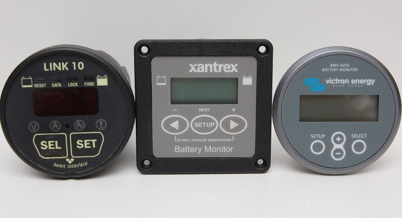
From left to right I have three generations of battery monitor represented. The original Link 10 was manufactured by Cruising Equipment Company and they really started a good thing. Despite many of the "LINK" products tending to be a little buggy they were generally well regarded and loved by boaters.
Somewhere along the way Cruising Equipment became Heart Interface and then Xantrex bought Heart Interface.
Xantrex then found TBS Electronics in the Netherlands and began importing and re-branding the TBS made monitor as the Xantrex XBM (pictured in the middle). The XBM was the identical monitor to the Victron 501 and was a very, very reliable device. It also offered a computer interface option something new to battery monitors at the time.
Eventually Xantrex made the switch to all TBS built battery monitors such as the current Link-Lite and Link-Pro. They have proven to be solid though very expensive units.
About the time Xantrex signed on to re-label the TBS monitors Victron found a new manufacturer to build their units, though I don't know who it is. The Victron BMV-602S is pictured on the right and bears little resemblance to the TBS built monitors.
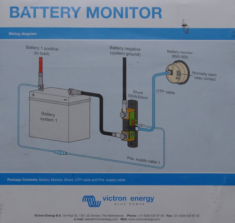
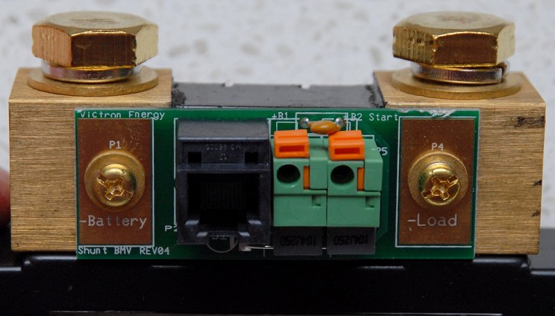
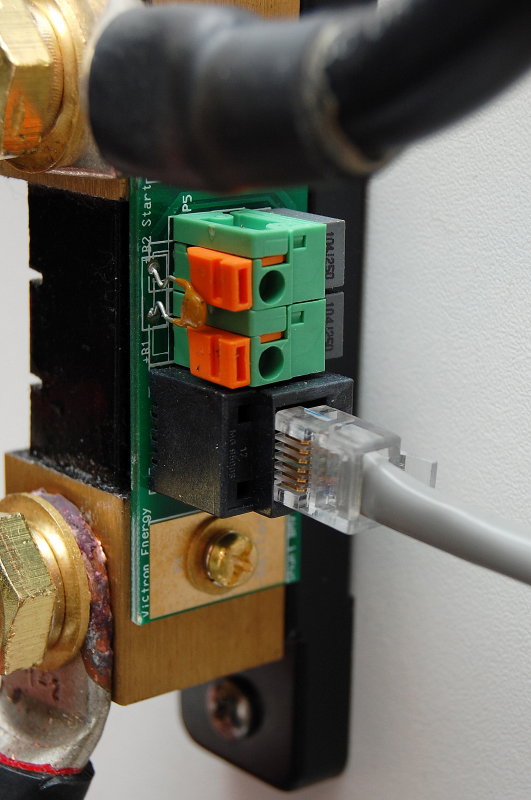
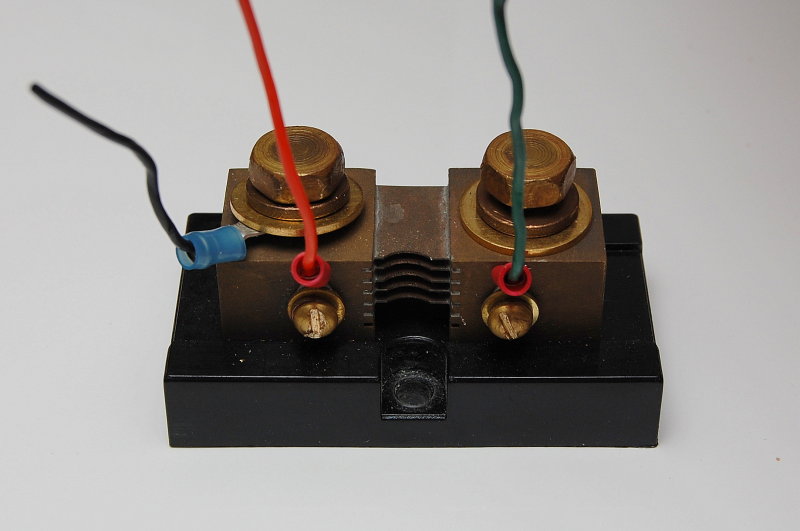
The Victron shunt is quite unique because they have added a printed circuit board to it so that wiring is much easier. Shunts are not really directional devices but because Victron added the printed circuit board / UTP cable connector it does make it directional.
The shunt is labeled -LOAD and -BATTERY. DO NOT wire this backwards or it will not work properly. The side labeled -BATTERY must be connected to the battery neg post and the side marked -LOAD must see the system negative loads.
This monitor is VERY easy to install. It has just two wires, a UTP cable & a power cable. The UTP cable is 10 meters or roughly 33 feet long, allowing plenty of display mounting options. The UTP cable is the only wire that needs to be run the monitor display. It's literally "plug & play". The UTP cable is very similar to a phone cable, only slightly more robust. The red power supply wire simply connects to the positive battery post and the +B1 terminal of the Shunt.
This shunt has two power supply inputs, +B1 & +B2 for two banks, as it can monitor the voltage of a second start/reserve bank.
I tried to wire this up on the bench to replicate what one might see on-board a boat. This is explanation is just far to difficult to illustrate on a boat. I actually photographed this quite a while ago, on a boat, and decided not to use any of the photos.
Obviously the house bank would be multiple batteries but the point is the same and a single battery was used for illustrative purposes only. If your boat is not wired with a positive or negative distribution buss it can help organize the wiring tremendously.
I have also shown a Blue Seas double MRBF (marine rated battery fuse) block on the battery post. I use one for the house bank and one fuse for the alternator which I generally always wire direct to the house bank.
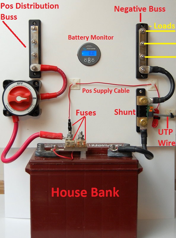
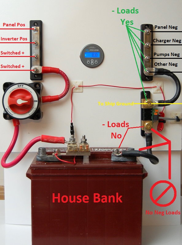
OK here's the gotcha we talked about. Nearly every instance of trouble shooting battery monitors I've come across can be lead directly to where you've connected your DC negative wires.
A shunt reads the loads on the system as measured as voltage drop, in mV levels, across the shunt. This shunt is a 500 amp 50 millivolt shunt. This means that at 500 amps there will be a 50 mV drop across the shunt. Knowing this the monitor manufacturer can make the display correspond to any load from 0 to 500 amps or 0 to 50 Mv.
If any load, such as a bilge pump ground, is wired ahead of the shunt or on the -BATTERY side of it, the load will NEVER be seen, recorded or measured by the monitor. All DC loads on-board should be read by the battery monitor. Inverters, battery chargers, alternators, solar, wind, DC distribution panel, LPG detectors etc., etc., on and on.
Keep in mind that many marine alternators are case grounded and thus the system ground, which on most boats is the engine block, is the ground path for the alternator. While I much prefer an isolated ground for alternators many boats just do not have alternators with this feature and they use the case as the ground. Due to this, the ships main ground connection should be connected to the -LOAD side of the shunt and NOT ahead of it or on the -BATTERY side.
Anywhere you see a green arrow is safe to connect DC negative load wires. The ONLY wire that should connect to the battery is a single negative jumper wire from the -BATTERY side of the shunt. No other wires should be connected on either the neg battery post or the -BATTERY side of the shunt.
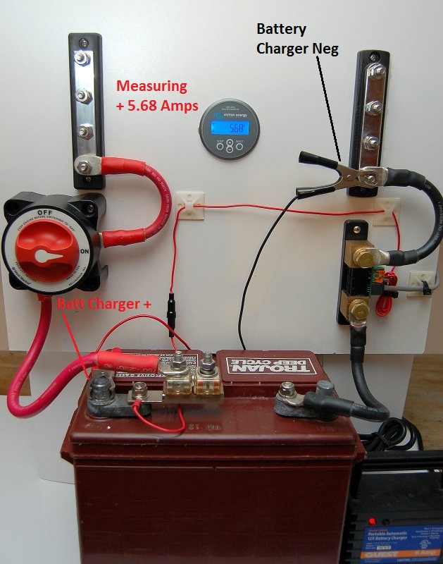
In this photo I have a Guest battery charger connected to the system. The battery monitor is reading a positive +5.68 amp charging current, as it should. Take note of the location of the black alligator clip in the next picture for a good example of why it really DOES matter where your negative system wires are connected.
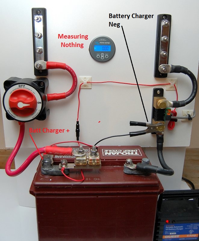
The ONLY thing different in this photo is the location of the chargers negative lead. The charger is still putting out about 5.68 amps, however, because the negative lead is on the wrong side of the shunt it can not be seen or measured by the shunt. If it can't be seen by the shunt it can not be logged or read by the battery monitor. Don't "jump the shunt"...
Whether you are drawing a load or feeding the system a charge current the negative load wires MUST be on the load side of the shunt NOT the -BATTERY side.
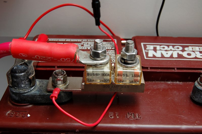
I am a strong believer in over current protection or fusing of battery banks, even start banks on smaller axillary engines despite this not being a requirement to meet in ABYC E-11.
This product made by Blue Seas is called an MRBF or Marine Rated Battery Fuse. These fuses are meant to protect the wiring from dead shorts and are easy to install. I use the double version for the bank and the alternator wire. As always choose your fuses based on the wire gauge you are protecting.
Every positive wire connected to a batter should be fused within 7" of the battery or as close as you can get. This includes inverters, alternators, battery chargers, bilge pumps or stereo memory wires.
Interestingly enough the black fuse holder for this Victron battery monitor is 7" from the ring terminal for the battery post.
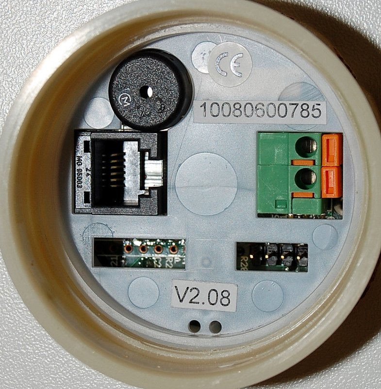
This is the back of the BMV-602S. There is a port for the computer connection kit, which can be purchased at additional cost, an alarm and the UTP cable connection port.
Once you have chosen your location, drilled the hole for the monitor and run the UTP cable, simply plug it in to the socket. If you can plug in a fax machine you already know how to connect the monitor to the shunt. This could not be any easier. Kudos to Victron for making this so easy!
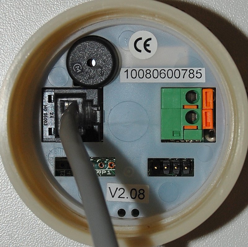
Now plug the UTP cable into the shunt.
Click, that's it!
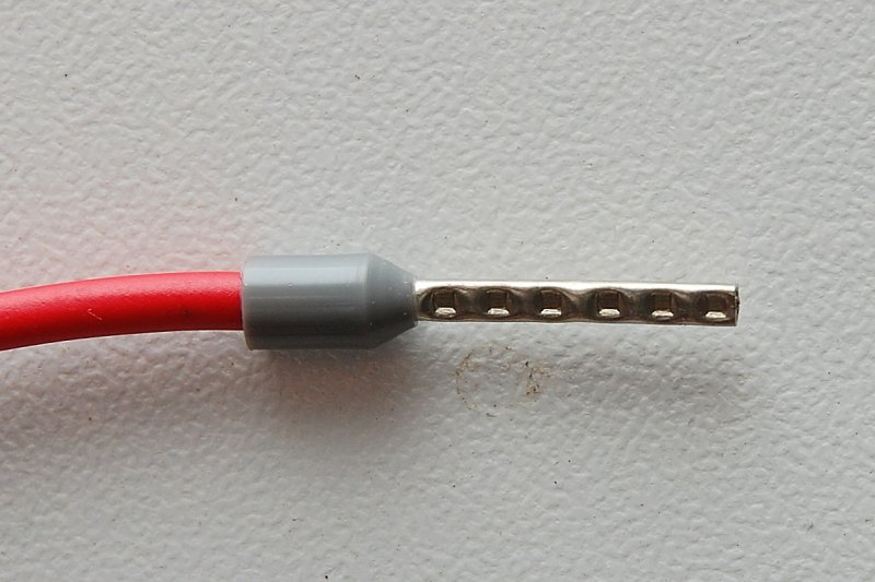
This is a close up of the crimped pin for the power supply cable. I would leave well enough alone and not cut the wire shorter unless it is absolutely necessary. This pin fits nicely in the shunt socket.
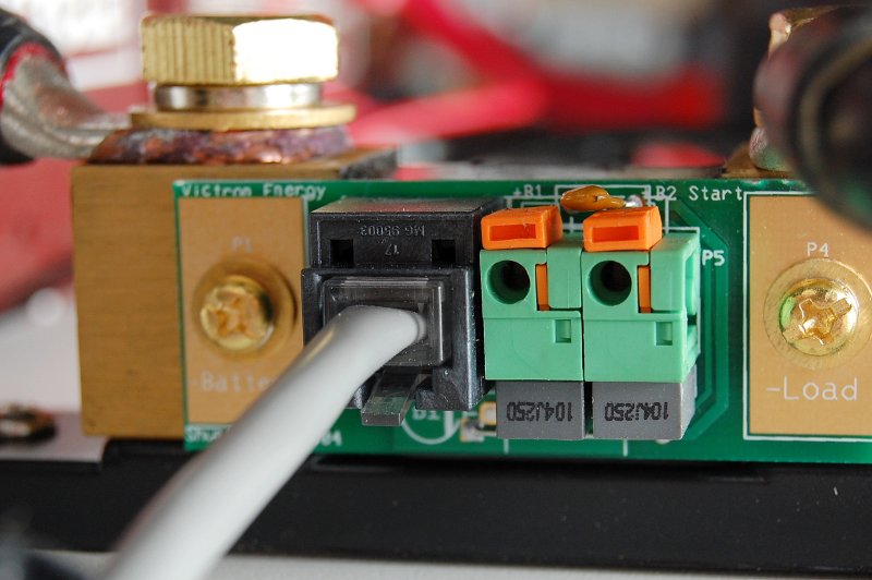
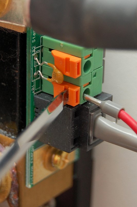
Use a small flat bladed screw driver and simply slide the orange tab towards the shunt to open the clamping mechanism. In this photo I have not yet slid the orange tab towards the shunt.
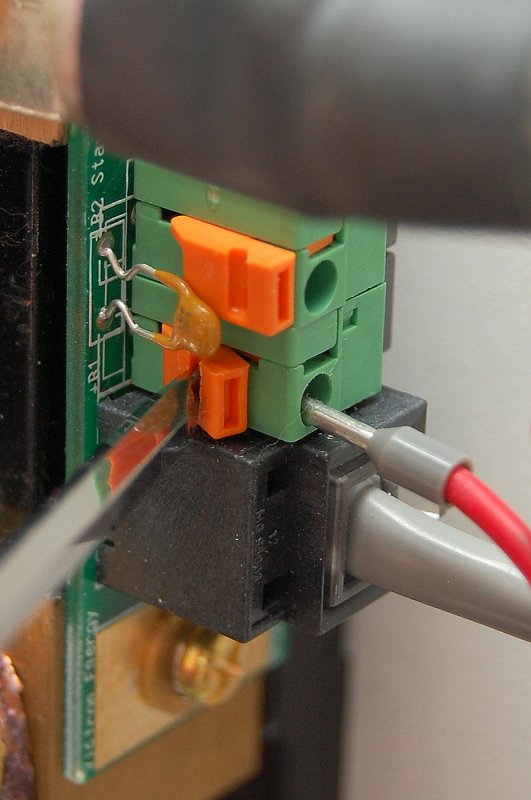
With the tab slid backwards simply push the pin into place. It will slide all the way into the socket just about up to the plastic.
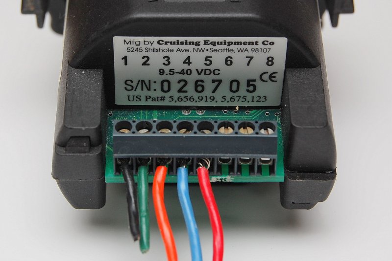
Here's a prime example of why I like the Victron simplicity. This is an older Link 10 and it requires five wires to be installed and then screwed down at the monitor end. This is certainly not difficult but requires some level of precision, access and can be a tad tedious.
The current Xantrex monitors, Link-Lite & Link-Pro, still connect exactly like the old Link 10 and on top of that they cost more money.
Rather than a shunt mounted PCB, like Victron has chosen, which offers true "plug and play" simplicity, the Link series shunts still require wire stripping, crimping, and the physical need to manually wire the shunt. The blue & red wires from the previous photo, and not pictured here on the shunt, go to the positive battery post with in-line fuses.
Again not difficult to wire but more tedious. I still have a Link-Pro on my own vessel and I am of the opinion that the Xantrex units are slightly more robustly built but you certainly pay dearly for that quality, which may not even be necessary.
That being said if you don't need to monitor the voltage of a second bank, really not all that necessary if it is just a starting or reserve bank, then Victron also offers the BMV-600S single bank monitor for just $184.25.
Ideally unless you are taking a "resting voltage" reading of a secondary bank it really won't tell you much of anything close to accurate anyway.
Battery monitors can display many different values on the screen including voltage, amp hours consumed, amperage, state of charge and more.
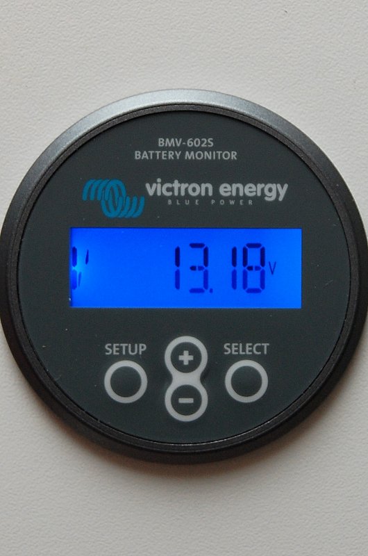
The "V" screen, as shown here, measures voltage for the house bank. This voltage reading is showing the battery being float charged.
This particular model, the Victron BMV-602S, can monitor the voltage of two banks as can the Xantrex Link-Pro & Link-Lite models from Xantrex.
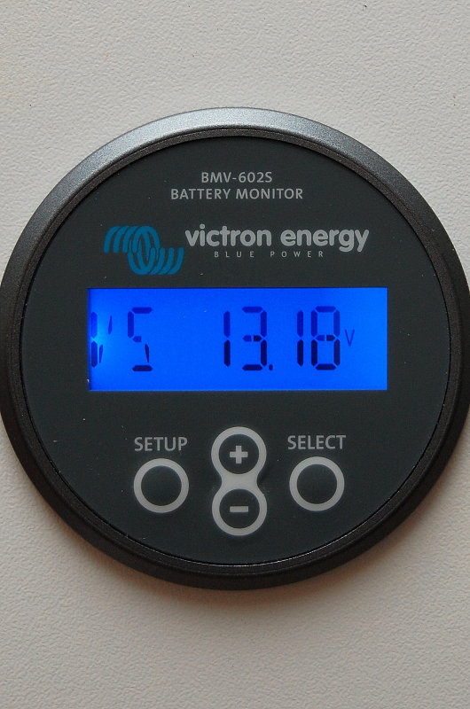
The "VS" screen tells you the voltage of a second bank. Seeing as I used one battery for this illustration the meter is showing the same voltage as the the "V" screen.
I should mention that there have been a couple of people on the boating forums complaining that the V & VS screens, even when fed from the same source voltage are not in sync or well calibrated. This sample happens to be properly calibrated but an experienced sailor and electrical engineer on SailboatOwners.com has had two units with voltage readings from .01 - .03 volts off when sensed from the identical source.
Is a variance of .01 to .03 volts a big deal? No, not at all, but I just wanted to make you aware so that you don't panic if your V & VS screens do not completely agree. Victron might need to do some better QC with the V & VS screen readings!
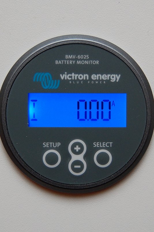
The "I" screen shows current in/out. This shot is showing no loads or charge current.
This "I" screen shot shows the monitor measuring a negative load. A negative load is denoted by the - symbol.

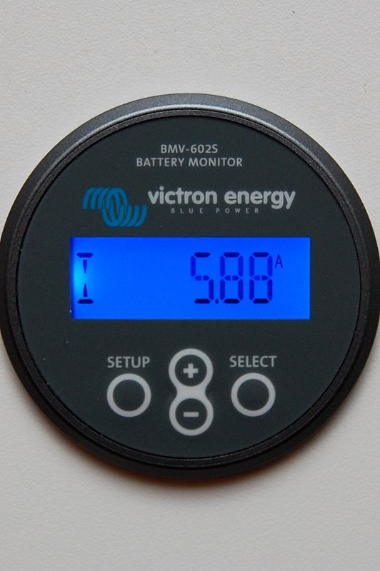
This screen shows a positive charge current as denoted by the lack of the - symbol..
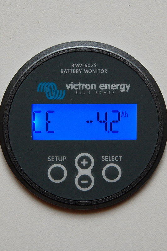
This is the CE or Consumed Energy screen. It shows the amount of amp hours consumed from the battery. After the battery receives a full charge this readout resets to 0.0 Ah denoting a fully synchronized monitor.
If you draw a current of 10 amps for a period of 4 hours you will show -40 Ah on the CE screen.
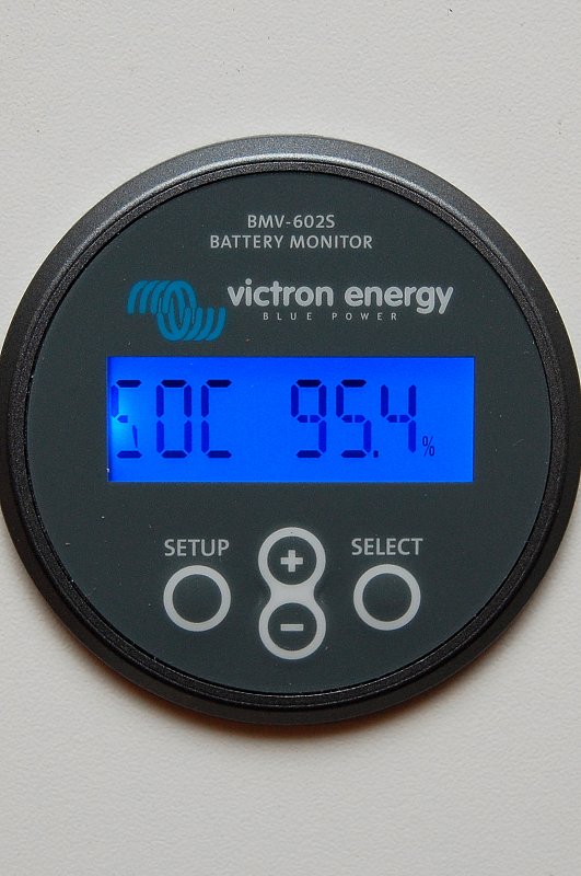
This is the SOC or State-of-charge screen. This screen is the best way to monitor the SOC of the battery with this monitor. This screen is only useful provided you have programmed the monitor correctly, it's synchronizing the way it should and is wired properly. This readout calculates the amount of energy available in the battery and is Peukert & CEF / Charge Efficiency corrected. The screen ranges from 0% = dead to 100% = full.
Counting amp hours is ok but may not always reflect the true state of charge of the battery. For example if the battery is drawn down heavily & at a high rate of current you will get less usable Ah's than its rating. If drawn slower than the 20 hour rating you can get more Ah's out of it. The SOC screen corrects for the Peukert component and CEF the Ah screen does not.
Please take the time to read the manual for these monitors as they are generally more difficult to program and master than the actual installation!
With new battery technologies costing three to ten times what wet cell technology does and many boaters moving to newer technologies such as Gel, AGM, TPPL and LiIon accurate monitoring of an expensive bank is almost a prerequisite.
People often ask me questions about how to install a battery monitor so I took some time and tried to make it simple. They are actually easy to install but there are a couple of "gotcha" traps that you may find your self falling victim to.. .
There are a fair number of monitors on the market. Blue Seas, Xantrex, Ample Power, BEP, Victron, NASA and a few others make them. Currently the Victron units are the easiest to install and also the least expensive making them a good value. A Victron BMV-600 single bank monitor can be purchased on my site Here (LINK) for $184.25. I chose to do this article with the Victron BMV-602S. I personally use a Xantrex Link Pro on my own boat but they all do basically the same thing and all work well.
From left to right I have three generations of battery monitor represented. The original Link 10 was manufactured by Cruising Equipment Company and they really started a good thing. Despite many of the "LINK" products tending to be a little buggy they were generally well regarded and loved by boaters.
Somewhere along the way Cruising Equipment became Heart Interface and then Xantrex bought Heart Interface.
Xantrex then found TBS Electronics in the Netherlands and began importing and re-branding the TBS made monitor as the Xantrex XBM (pictured in the middle). The XBM was the identical monitor to the Victron 501 and was a very, very reliable device. It also offered a computer interface option something new to battery monitors at the time.
Eventually Xantrex made the switch to all TBS built battery monitors such as the current Link-Lite and Link-Pro. They have proven to be solid though very expensive units.
About the time Xantrex signed on to re-label the TBS monitors Victron found a new manufacturer to build their units, though I don't know who it is. The Victron BMV-602S is pictured on the right and bears little resemblance to the TBS built monitors.
The Victron shunt is quite unique because they have added a printed circuit board to it so that wiring is much easier. Shunts are not really directional devices but because Victron added the printed circuit board / UTP cable connector it does make it directional.
The shunt is labeled -LOAD and -BATTERY. DO NOT wire this backwards or it will not work properly. The side labeled -BATTERY must be connected to the battery neg post and the side marked -LOAD must see the system negative loads.
This monitor is VERY easy to install. It has just two wires, a UTP cable & a power cable. The UTP cable is 10 meters or roughly 33 feet long, allowing plenty of display mounting options. The UTP cable is the only wire that needs to be run the monitor display. It's literally "plug & play". The UTP cable is very similar to a phone cable, only slightly more robust. The red power supply wire simply connects to the positive battery post and the +B1 terminal of the Shunt.
This shunt has two power supply inputs, +B1 & +B2 for two banks, as it can monitor the voltage of a second start/reserve bank.
I tried to wire this up on the bench to replicate what one might see on-board a boat. This is explanation is just far to difficult to illustrate on a boat. I actually photographed this quite a while ago, on a boat, and decided not to use any of the photos.
Obviously the house bank would be multiple batteries but the point is the same and a single battery was used for illustrative purposes only. If your boat is not wired with a positive or negative distribution buss it can help organize the wiring tremendously.
I have also shown a Blue Seas double MRBF (marine rated battery fuse) block on the battery post. I use one for the house bank and one fuse for the alternator which I generally always wire direct to the house bank.
OK here's the gotcha we talked about. Nearly every instance of trouble shooting battery monitors I've come across can be lead directly to where you've connected your DC negative wires.
A shunt reads the loads on the system as measured as voltage drop, in mV levels, across the shunt. This shunt is a 500 amp 50 millivolt shunt. This means that at 500 amps there will be a 50 mV drop across the shunt. Knowing this the monitor manufacturer can make the display correspond to any load from 0 to 500 amps or 0 to 50 Mv.
If any load, such as a bilge pump ground, is wired ahead of the shunt or on the -BATTERY side of it, the load will NEVER be seen, recorded or measured by the monitor. All DC loads on-board should be read by the battery monitor. Inverters, battery chargers, alternators, solar, wind, DC distribution panel, LPG detectors etc., etc., on and on.
Keep in mind that many marine alternators are case grounded and thus the system ground, which on most boats is the engine block, is the ground path for the alternator. While I much prefer an isolated ground for alternators many boats just do not have alternators with this feature and they use the case as the ground. Due to this, the ships main ground connection should be connected to the -LOAD side of the shunt and NOT ahead of it or on the -BATTERY side.
Anywhere you see a green arrow is safe to connect DC negative load wires. The ONLY wire that should connect to the battery is a single negative jumper wire from the -BATTERY side of the shunt. No other wires should be connected on either the neg battery post or the -BATTERY side of the shunt.
In this photo I have a Guest battery charger connected to the system. The battery monitor is reading a positive +5.68 amp charging current, as it should. Take note of the location of the black alligator clip in the next picture for a good example of why it really DOES matter where your negative system wires are connected.
The ONLY thing different in this photo is the location of the chargers negative lead. The charger is still putting out about 5.68 amps, however, because the negative lead is on the wrong side of the shunt it can not be seen or measured by the shunt. If it can't be seen by the shunt it can not be logged or read by the battery monitor. Don't "jump the shunt"...
Whether you are drawing a load or feeding the system a charge current the negative load wires MUST be on the load side of the shunt NOT the -BATTERY side.
I am a strong believer in over current protection or fusing of battery banks, even start banks on smaller axillary engines despite this not being a requirement to meet in ABYC E-11.
This product made by Blue Seas is called an MRBF or Marine Rated Battery Fuse. These fuses are meant to protect the wiring from dead shorts and are easy to install. I use the double version for the bank and the alternator wire. As always choose your fuses based on the wire gauge you are protecting.
Every positive wire connected to a batter should be fused within 7" of the battery or as close as you can get. This includes inverters, alternators, battery chargers, bilge pumps or stereo memory wires.
Interestingly enough the black fuse holder for this Victron battery monitor is 7" from the ring terminal for the battery post.
This is the back of the BMV-602S. There is a port for the computer connection kit, which can be purchased at additional cost, an alarm and the UTP cable connection port.
Once you have chosen your location, drilled the hole for the monitor and run the UTP cable, simply plug it in to the socket. If you can plug in a fax machine you already know how to connect the monitor to the shunt. This could not be any easier. Kudos to Victron for making this so easy!
Now plug the UTP cable into the shunt.
Click, that's it!
This is a close up of the crimped pin for the power supply cable. I would leave well enough alone and not cut the wire shorter unless it is absolutely necessary. This pin fits nicely in the shunt socket.
Use a small flat bladed screw driver and simply slide the orange tab towards the shunt to open the clamping mechanism. In this photo I have not yet slid the orange tab towards the shunt.
With the tab slid backwards simply push the pin into place. It will slide all the way into the socket just about up to the plastic.
Here's a prime example of why I like the Victron simplicity. This is an older Link 10 and it requires five wires to be installed and then screwed down at the monitor end. This is certainly not difficult but requires some level of precision, access and can be a tad tedious.
The current Xantrex monitors, Link-Lite & Link-Pro, still connect exactly like the old Link 10 and on top of that they cost more money.
Rather than a shunt mounted PCB, like Victron has chosen, which offers true "plug and play" simplicity, the Link series shunts still require wire stripping, crimping, and the physical need to manually wire the shunt. The blue & red wires from the previous photo, and not pictured here on the shunt, go to the positive battery post with in-line fuses.
Again not difficult to wire but more tedious. I still have a Link-Pro on my own vessel and I am of the opinion that the Xantrex units are slightly more robustly built but you certainly pay dearly for that quality, which may not even be necessary.
That being said if you don't need to monitor the voltage of a second bank, really not all that necessary if it is just a starting or reserve bank, then Victron also offers the BMV-600S single bank monitor for just $184.25.
Ideally unless you are taking a "resting voltage" reading of a secondary bank it really won't tell you much of anything close to accurate anyway.
Battery monitors can display many different values on the screen including voltage, amp hours consumed, amperage, state of charge and more.
The "V" screen, as shown here, measures voltage for the house bank. This voltage reading is showing the battery being float charged.
This particular model, the Victron BMV-602S, can monitor the voltage of two banks as can the Xantrex Link-Pro & Link-Lite models from Xantrex.
The "VS" screen tells you the voltage of a second bank. Seeing as I used one battery for this illustration the meter is showing the same voltage as the the "V" screen.
I should mention that there have been a couple of people on the boating forums complaining that the V & VS screens, even when fed from the same source voltage are not in sync or well calibrated. This sample happens to be properly calibrated but an experienced sailor and electrical engineer on SailboatOwners.com has had two units with voltage readings from .01 - .03 volts off when sensed from the identical source.
Is a variance of .01 to .03 volts a big deal? No, not at all, but I just wanted to make you aware so that you don't panic if your V & VS screens do not completely agree. Victron might need to do some better QC with the V & VS screen readings!
The "I" screen shows current in/out. This shot is showing no loads or charge current.
This "I" screen shot shows the monitor measuring a negative load. A negative load is denoted by the - symbol.
This screen shows a positive charge current as denoted by the lack of the - symbol..
This is the CE or Consumed Energy screen. It shows the amount of amp hours consumed from the battery. After the battery receives a full charge this readout resets to 0.0 Ah denoting a fully synchronized monitor.
If you draw a current of 10 amps for a period of 4 hours you will show -40 Ah on the CE screen.
This is the SOC or State-of-charge screen. This screen is the best way to monitor the SOC of the battery with this monitor. This screen is only useful provided you have programmed the monitor correctly, it's synchronizing the way it should and is wired properly. This readout calculates the amount of energy available in the battery and is Peukert & CEF / Charge Efficiency corrected. The screen ranges from 0% = dead to 100% = full.
Counting amp hours is ok but may not always reflect the true state of charge of the battery. For example if the battery is drawn down heavily & at a high rate of current you will get less usable Ah's than its rating. If drawn slower than the 20 hour rating you can get more Ah's out of it. The SOC screen corrects for the Peukert component and CEF the Ah screen does not.
Please take the time to read the manual for these monitors as they are generally more difficult to program and master than the actual installation!
