Wiring for Tach on Alternator

Sep 24, 2010
34
Beneteau 321 Edgewater, MD
I have attached a pic below to see if it helps.

I have a Perkins M30 that I have replaced the instrument panel on and everything is working, except the tach. The tach does not budge, so I don't believe it to be a calibration issue.

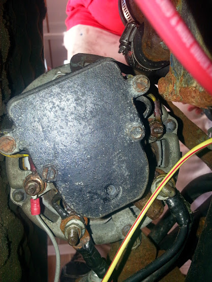
On the back of my alternator there are four posts. Red, Black, and two smaller ones that come off the regulator. I believe that the factory panel was wired like I currently have it, but I am not 100% positive as it was several months ago that I took it apart.

Also, I have one wire left over on the new harness that I don't believe was used in the factory panel, the alternator excitation wire.

So, what am I doing wrong.

 
Feb 6, 1998
11,665
Canadian Sailcraft 36T Casco Bay, ME
Fire up the alt and with it running test the two terminals at 9:00 and 3:00 (gray wire and yellow wire terminals. Use a DVM set to DC volts. You should see roughly half the voltage of the B+/output terminal. This is a quick & dirty test to confirm the AC Tap.. Which ever terminal has that voltage is your stator tap. Some of those alts had two stator taps. If the gray wire stud is showing 5V to 7V then it is likely working correctly and the issue is in your tach or wiring..
 
Sep 24, 2010
34
Beneteau 321 Edgewater, MD
Alright Maine, I got another one for you.

We put the boat in the water yesterday which allowed me to do some more troubleshooting with the electrical system.

It started with the alternator not charging. There was no voltage coming off of the alternator at all with the motor running. I traced the positive off the alternator to this black box with four posts.

The first post is the wire off of the alternator, and the last post is the connection to the isolator.

The to in the middle have existing wires running off of them that lead to the instrument panel (red and black).

Initially, I connected the red to 12V and the black to ground. The connection shorted out and was quickly disconnected. After some more troubleshooting, I figured out that if I apply 12V to one wire (either red or black) and leave the other wire disconnected, everything starts working. The alternator charges and the tachometer starts working. I assume that this is some type of 12V exciter setup, but I am confused as to why there are two wires if only one works and where the other wire goes. Both wires were originally hooked up to something at the instrument panel, but since everything was such a mess before, I do not know where or to what. Is one a 12V constant and the other 12V switched? The only thing I can make out on the box is VDO something.

Thanks for any input you can give.
 
Feb 6, 1998
11,665
Canadian Sailcraft 36T Casco Bay, ME
Nothing?
Without a better picture it is hard to tell. It appears to be a shunt for an ammeter but could be a fuse block very hard to tell from the image. If you can draw out where each wire goes we may be able to help better..
 
Feb 26, 2004
22,759
Catalina 34 224 Maple Bay, BC, Canada
In internet boating questions, smells, sounds, leaks, and electrical questions with photographs and no wiring diagrams are almost impossible to diagnose. Maine Sail's right, give us some more information to help you out.
 
Last edited:
Jun 6, 2006
6,990
currently boatless wishing Harrington Harbor North, MD
I'm thinking that the alternator needs that exciter wire to "get it going". Once it is producing the exciter does not do anything but light the idiot light if there is an alternator fault.
i'd google your alternator to see if there is a diagram or something to clue you in to which wire goes where. Typically the exciter wire goes to the alternator rotor through a diode and resistor and comes from the ignition via the idiot light. So the ignition is on and the light lights up due to current flowing into the alternator rotor. Once the alternator fires up the voltage on the regulator side comes up above the batter voltage and the current stops and the idiot light goes out. There are many variations though.