Waterproof Step Down Butt Connectors?
- Thread starter sully75
- Start date
Butt Connectors
Why would you ever want to use a crimp type butt connector?
Why would you drop wire size so dramatically?
If you are dead set on causing a fire hazard condition on your boat here is the least dangerous and only reliable way to make connections:
1) Cut away ALL crimp connectors.
2) Buy COPPER solder on fittings for proper fit and type of connection (eg: spade, loop, etc.)
3) Purchase an assortment of good quality shrink tubing (appropriate sizes and colors)
4) Strip and tin the wire ends.
5) Slip the shrink tube over the wire.
6) Slip the connector on and solder it on (no cold solder joints)
7) Optional, but worth it: Apply a light coating of Liquid Tape to solder joint.
8) Slide shrink tube over wire and apply heat.
9) Enjoy the fact that the joint won't short out EVER!
Lets begin with the obvious:So I have a large quantity of 12 gauge wire, but need to wire some things that are 16 gauge. I don't see much in the way of step down butt connectors, at least waterproof ones. Ancor makes some without heat shrink.
Is there a source for good quality heat shrink step down connectors? Or should I use the Ancor connectors and put heat shrink over them? Or just buy smaller wire?
Why would you ever want to use a crimp type butt connector?
Why would you drop wire size so dramatically?
If you are dead set on causing a fire hazard condition on your boat here is the least dangerous and only reliable way to make connections:
1) Cut away ALL crimp connectors.
2) Buy COPPER solder on fittings for proper fit and type of connection (eg: spade, loop, etc.)
3) Purchase an assortment of good quality shrink tubing (appropriate sizes and colors)
4) Strip and tin the wire ends.
5) Slip the shrink tube over the wire.
6) Slip the connector on and solder it on (no cold solder joints)
7) Optional, but worth it: Apply a light coating of Liquid Tape to solder joint.
8) Slide shrink tube over wire and apply heat.
9) Enjoy the fact that the joint won't short out EVER!
The scare tactics in this post are without basis. The entire marine industry, as well as aerospace, US Military, automotive and heavy industry go the other way and use millions of crimps each month... Properly made crimps are 100% reliable, repeatable and last for many, many decades..Lets begin with the obvious:
Why would you ever want to use a crimp type butt connector?
Why would you drop wire size so dramatically?
If you are dead set on causing a fire hazard condition on your boat here is the least dangerous and only reliable way to make connections:
1) Cut away ALL crimp connectors.
2) Buy COPPER solder on fittings for proper fit and type of connection (eg: spade, loop, etc.)
3) Purchase an assortment of good quality shrink tubing (appropriate sizes and colors)
4) Strip and tin the wire ends.
5) Slip the shrink tube over the wire.
6) Slip the connector on and solder it on (no cold solder joints)
7) Optional, but worth it: Apply a light coating of Liquid Tape to solder joint.
8) Slide shrink tube over wire and apply heat.
9) Enjoy the fact that the joint won't short out EVER!
Crimp step down butt connectors are used all the time when installing bilge pumps because the bilge pump makers supply short pigtails of wire too small to give proper performance when connected to the system so you need to bump up the wire size to avoid voltage drop issues... They are also used on many appliances etc. that come with pig tails especially where watertight terminations are required, such as navigation lights..
Adhesive lined heat shrink butt connectors are also used on millions of well pumps in this country which can be submerged up to 300+ feet below water. Our old well pump was 340 feet deep and a true artesian. It bubbled out the well cap almost year round. The pump was installed with adhesive line heat shrink butt connectors. That pump is still going 20 years later, 20 years of 100% submersion with adhesive lined heat shrink crimped on butt connectors......
In marine environments properly made crimp connections are historically more reliable than soldered connections. This is why the standards are what they are, and why the standards disallow solder as the "sole means of connection" in the wiring.....
I install a few thousand crimp connections every year and have never once had one fail... Poorly made crimps (wrong tools) are just as bad as poorly made solder connections.
The key here which deserves to be highlighted is the term "proper".
Proper solder joints require secure mechanical connection. It's a two step process and because many people fail to first mechanically bond before soldering, or don't know how to properly solder, the lowest common denominator results -that being the recommendation to crimp.
Crimping is much easier to do properly, hence, the wide- held assumption it is preferable for the novice to simply buy a good crisper and have at it. However, the perception is often different from reality. As a practical matter, it is impossible to know definitively that the crimp is solid unless one does destructive testing.
A proper bonded and soldered joint, however, can be identified visually and therefore is preferred by many people I consider to be experienced. Such connection offer twice the protection of a simple crimp. Just ask the widows of the three astronauts burned to death while sitting in the Apollo 1 capsule how good crimps can be...
As I have said many times before "if you don't know how to solder, don't". I just got back from my local ham shop with about 30 PL-259's both solder and crimp/solder. Went through almost a dozen between last week and this week. Four were the crappy Shakespere Easy VHF connectors that had failed, and the rest were all bad solder jobs.... If you do know how to properly crimp, then solder, by all means have at it. Sadly for me about 95% of the solder jobs I see on boats have not been done properly...The key here which deserves to be highlighted is the term "proper".
Proper solder joints require secure mechanical connection. It's a two step process and because many people fail to first mechanically bond before soldering, or don't know how to properly solder, the lowest common denominator results -that being the recommendation to crimp.
I test my crimp tools twice per year. Only once have I needed to send one out for re-calibration. It had drifted by 6-7 pounds but was still exceeding Mil-Spec.. The results are repeatable to within 1-2 pounds consistently. All the tools I use exceed Mil-Spec standards for crimp terminations and most well exceed it. My tools are no different than what are used on the airplanes we fly in and in fact come from places like Boeing, Bombardier/Lear etc. as I buy them from their re-calibrators, at a huge savings.....Crimping is much easier to do properly, hence, the wide- held assumption it is preferable for the novice to simply buy a good crisper and have at it. However, the perception is often different from reality. As a practical matter, it is impossible to know definitively that the crimp is solid unless one does destructive testing.
A proper bonded and soldered joint, however, can be identified visually and therefore is preferred by many people I consider to be experienced.
Please tell me how to visually identify a PL-259 that has not been over heated and melted the dialectic...? How about closed end battery lugs? I've had a few solder only lugs that have failed.. Observing the pin on a 259 is easy but the shield is tough. I can't walk up to someone Else's work and see how the terminal looks inside. I have to use an SWR to see how badly the PL-259 soldering was botched...
???? I don't recall crimped connections ever being blamed or found to be the cause in that investigation...??Such connection offer twice the protection of a simple crimp. Just ask the widows of the three astronauts burned to death while sitting in the Apollo 1 capsule how good crimps can be...
Apollo Findings Summary - NASA
Apollo Investigation & Analysis - NASA
4. CAUSE OF THE APOLLO 204 FIRE
The fire in Apollo 204 was most probably brought about by some minor malfunction or failure of equipment or wire insulation. This failure, which most likely will never be positively identified, initiated a sequence of events that culminated in the conflagration.
SUMMARY Although the Board was not able to determine conclusively the specific initiator of the Apollo 204 fire, it has identified the conditions which led to the disaster. These conditions were:
- A sealed cabin, pressurized with an oxygen atmosphere.
- An extensive distribution of combustible materials in the cabin.
- Vulnerable wiring carrying spacecraft power.
- Vulnerable plumbing carrying a combustible and corrosive coolant.
- Inadequate provisions for the crew to escape.
- Inadequate provisions for rescue or medical assistance.
As with most things, opinions vary. PL 259 crimp connections invariably damage either the dielectric or the braid, or sometimes both. The evidence is there if you wnt to verify it. We are all subject to our individual perspectives. My intent is to point out opinions are just that! Not necessarily fact...
Don,
I've probally tested 4 or 5k Pl-259 crimp connectors over the years, I run one of the test labs for Amphenol, and have never seen one that had either damaged braid or dielectric when done with proper connectors and tooling.
The testing consisted of, insertion loss, return loss, intermod, impedance from 10 kHz to 3 gHz then were cross sectioned to evaluate the mechanical integrity.
Of returns from the field, the main faults were improper stripping, wrong tooling, bad tooling or crimping and wrong cable connector combination. One other one junk cable.
Send me some of those damaged connectors and I'll gladly test them and give you a formal report. PM me for contact info.
I was going to stay out of this, but just couldn't
I don't have any but have seen them repeatedly and among experienced professional antenna installers, the story is similar. It doesn't make sense that our opinions are so contrary so I assume the difference is not the equipment but rather either the connectors or the person operating the equipment.Don,
I've probally tested 4 or 5k Pl-259 crimp connectors over the years, I run one of the test labs for Amphenol, and have never seen one that had either damaged braid or dielectric when done with proper connectors and tooling.
The testing consisted of, insertion loss, return loss, intermod, impedance from 10 kHz to 3 gHz then were cross sectioned to evaluate the mechanical integrity.
Of returns from the field, the main faults were improper stripping, wrong tooling, bad tooling or crimping and wrong cable connector combination. One other one junk cable.
Send me some of those damaged connectors and I'll gladly test them and give you a formal report. PM me for contact info.
I was going to stay out of this, but just couldn't
As it relates to this thread, sailors don't generally make for generalities. I can only relate my experience or that of people I consider having some expertise. If start line expertise is any indicator of soldering or crimping technique, the race I just did indicates lots of bad electrical connections exist on boats.
Fred,I run one of the test labs for Amphenol
I did my small part to support your job today... This is my Amphenol/Connex portion of my trip to the store today...
") The 83-1SP is still one of my favorites... I do like the crimp/solder Connex 259 too....
The 83-1SP is still one of my favorites... I do like the crimp/solder Connex 259 too....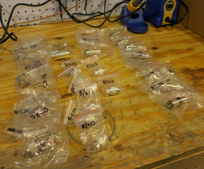
I do not particulary care for the PL-259 type connectors, I'd rather use N connectors, much better VHF and above to around 5 gHz.
I'm not in the RF division, I'm in the high speed interconnect division, we do cable assemblies, to 26 gHz.
I also prefer the solder center connector, the deformation of the crimp center gives a slight bump in the return loss. It is not enough to worry about, but I know it's there.
Don, if you are seeing broken braid and damaged dielectric, the techs need training on prep and their tools calibrated. All to often I see techs using the cheapest crimpers that they can find, decent crimpers start at about 200 with another 100 for each different connector. There is a reason that they cost so much.
Just because I think this may be the first time I have ever caught you being incorrect on a technicality... :naughty:Using linemans splices/wire twisting on stranded wire is verboten not only by the ABYC/NMMA etc. but also by NASA, Mil-Spec etc....
Page 83/84 of http://www.hq.nasa.gov/office/codeq/doctree/87394.pdf states the proper NASA approved method of doing a Western Union/Lineman Splice, and the document was last revised in March of 2011, so it's not something horribly out of date.
Therefore
in this one particular case, it IS NASA approved, and they require it to be soldered, though I know that means nothing for ABYC or if it's appropriate for our boats (especially since it does require solid core wire to work, NOT stranded).Brian,
Look carefully at page 84 do you see any stranded wire in the western union splice?
Stranded wire is verbotton by nasa, mil spec, ipc, iec and a multitude of others.
Look carefully at page 84 do you see any stranded wire in the western union splice?
Stranded wire is verbotton by nasa, mil spec, ipc, iec and a multitude of others.
Fred, I understand that, Re-read my post, I mentioned that it requires solid wire. I was just pointing out that the western union splice IS technically accepted by NASA when done properly and with limitations (non stranded wire), contrary to what MS indicated.Brian,
Look carefully at page 84 do you see any stranded wire in the western union splice?
Stranded wire is verbotton by nasa, mil spec, ipc, iec and a multitude of others.
I was not trying to add anything actually useful to the discussion, or argue in favor of soldering connections without mechanical crimps. I agree that proper crimps are reliable and preferred, I just wanted to relish in catching MS on a minor technicality
Sorry Brian, Your last line didn't register, and I was referring to Maine's statement was only about stranded wire.
Just because I think this may be the first time I have ever caught you being incorrect on a technicality... :naughty:
Page 83/84 of http://www.hq.nasa.gov/office/codeq/doctree/87394.pdf states the proper NASA approved method of doing a Western Union/Lineman Splice, and the document was last revised in March of 2011, so it's not something horribly out of date.
Therefore
Unfortunately you did not catch me on anything incorrect. I specifically referred to stranded wire. Read what you quoted from me.... See the part where I said STRANDED WIRE......
NASA and the ABYC both don't allow WU splices in STRANDED WIRE... We don't used solid wire on boats so this makes the WU splice unacceptable as a "mechanical connection" under ABYC standards....
NASA does NOT approve of a WU splice in stranded wire, just as I said, stranded wire, in your quote of mine... I never said NASA does not allow a WU I said they don't allow it in STRANDED wire.... The WU should only be used with solid wire....
This is what you quoted from me, but you apparently missed the part I bolded.
Using linemans splices/wire twisting on stranded wire is verboten not only by the ABYC/NMMA etc. but also by NASA, Mil-Spec etc....