Hi all!
It's winter time up here in the frozen north, but I'm already getting excited for spring. Only 4(ish) more months until launch!
In the meantime, I'm starting to plan out projects. One project about which I am quite excited is an upgrade to our alternator charging system.
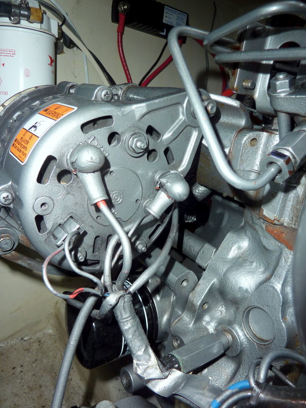
We currently have the OEM Hitachi alternator wired to the mid-90's Hunter shunt, dividing charging to the start and house batteries (currently a group 24 start and 4D house, both lead acid).
I am now in possession of two new Victron DC to DC chargers -- a Victron Orion XS 50 amp and a Tr Smart 9 amp DC to DC charger. The 50 amp would be between the alternator and the house battery, the 9 amp between the house battery and the start battery. The goal here is to output cleaner power from the alternator to the batteries (real, actual voltage controlled bulk and float stages) , baby the alternator for more extended higher amperage output (as I've understood this is accomplished by current limiting the charger to 40 amps, keeping the alternator from moving to "self protect" mode as quickly), and potentially prep for a future upgrade to Lithium.
The more immediate planning question (and the reason for this post) is best determining how to wire the new units. Specifically: should I (mostly) re-use the existing alternator charging wiring, or should I run new wires and connect these units directly to the batteries. I see advantages/disadvantages to both options:
Keeping the existing layout:
Pros: Physically simpler wiring, DC units are mounted in a compartment with more space, the ability to shut off power between the battery and alternator
Cons: Wiring may be a little undersized (it's the OEM Hunter wiring), extra failure points with the battery switches in line
New wiring:
Pros: A simpler system (more direct wires), fewer failure points, right sized wire
Cons: Some space concerns for the House to Start charger location, more cabling to pull, more contact points on the batteries/bus bars
I've included a great MS Paint drawing of the existing configuration and how the two options may look. The drawing is basic -- I'd obviously include fuses, wiring for indication that the motor is running and (most obviously) I used a red line, but the negative would be wired appropriately for the circuit. With that would folks with more expertise in this area recommend?
It's winter time up here in the frozen north, but I'm already getting excited for spring. Only 4(ish) more months until launch!
In the meantime, I'm starting to plan out projects. One project about which I am quite excited is an upgrade to our alternator charging system.
We currently have the OEM Hitachi alternator wired to the mid-90's Hunter shunt, dividing charging to the start and house batteries (currently a group 24 start and 4D house, both lead acid).
I am now in possession of two new Victron DC to DC chargers -- a Victron Orion XS 50 amp and a Tr Smart 9 amp DC to DC charger. The 50 amp would be between the alternator and the house battery, the 9 amp between the house battery and the start battery. The goal here is to output cleaner power from the alternator to the batteries (real, actual voltage controlled bulk and float stages) , baby the alternator for more extended higher amperage output (as I've understood this is accomplished by current limiting the charger to 40 amps, keeping the alternator from moving to "self protect" mode as quickly), and potentially prep for a future upgrade to Lithium.
The more immediate planning question (and the reason for this post) is best determining how to wire the new units. Specifically: should I (mostly) re-use the existing alternator charging wiring, or should I run new wires and connect these units directly to the batteries. I see advantages/disadvantages to both options:
Keeping the existing layout:
Pros: Physically simpler wiring, DC units are mounted in a compartment with more space, the ability to shut off power between the battery and alternator
Cons: Wiring may be a little undersized (it's the OEM Hunter wiring), extra failure points with the battery switches in line
New wiring:
Pros: A simpler system (more direct wires), fewer failure points, right sized wire
Cons: Some space concerns for the House to Start charger location, more cabling to pull, more contact points on the batteries/bus bars
I've included a great MS Paint drawing of the existing configuration and how the two options may look. The drawing is basic -- I'd obviously include fuses, wiring for indication that the motor is running and (most obviously) I used a red line, but the negative would be wired appropriately for the circuit. With that would folks with more expertise in this area recommend?
Attachments
-
 480.2 KB Views: 88