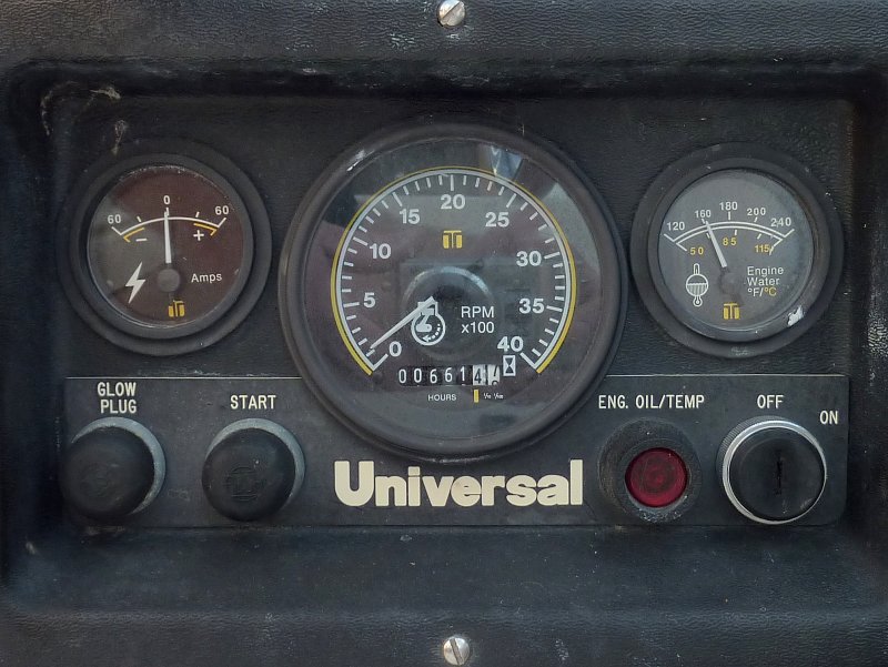
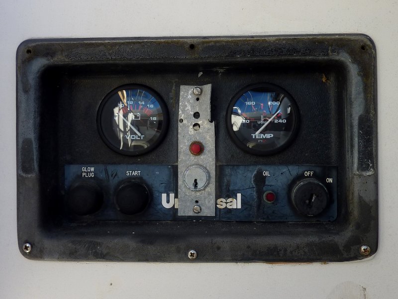
If your Universal engine panel looks like the one below, and has an ammeter, you are due for some wiring fixes.
The factory wiring, with an ammeter in the panel, is flat out dangerous and this really needs to be addressed if it has not yet. It amazes me how many boats are out there still using this unsafe set up.
If you have an ammeter in your panel disconnect the wiring, remove it and jump your alternator 6" over to the starter post with heavy wire. The ammeter can easily be replaced with a volt gauge. Another alternator wiring alternative is to run your alternator direct to the house bank with a fuse or breaker within 7" of the battery and then add a combining relay or Echo Charger..
I have also measured voltage drops of 1.2+ volts or more at just 10A of charge current through these circuits. That means your alt is putting out 14.2V+ and the battery is seeing just 13.0 volts and is being chronically under charged.
Engine Panel With Ammeter = Dangerous
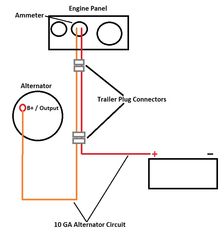
Here's a very crude diagram that shows the alternator charging circuit most often found on these early Universal engines. Universal/Westerbeke Corp later changed this dangerous set up, removed the ammeter and jumped the alternator directly to the starter lug. Interestingly enough many of the Westerbeke engines never used a factory installed ammeter and it was sold as an option unless a builder wanted them that way.
The factory charging circuit leaves the alternator with an orange 10GA wire then most often travels through TWO trailer type connectors to an ammeter at the engine panel. This high amperage current then has to travel all the way back to the battery switch (please note I did not draw the battery switch on this diagram), through more undersized wire, where it finally picks up some larger gauge wire before finally heading to the battery to charge it. These factory circuits often had a 30A fuse in them which was undersized even for some of the alternators shipped on these engines. Owners often put higher amp fuses in or bypassed them all together...
It is not that the ammeter itself is dangerous, unless you upgrade the alternator beyond factory specs, but rather it is the undersized wiring running from the alt and to the batteries that makes this set up dangerous.
The existing alternator charging circuit, with ammeter, runs as far as 25+ feet on some boats before it gets to the battery banks. On most of these panels the entire current of the alternator runs through 10GA wire and a ridiculous trailer type connector that is a huge point of resistance as these boats age. I have pulled many of these connectors and wires out that were literally melted.
With house power demands getting larger and larger and battery banks getting bigger and bigger, and accepting significantly more charging current, these circuits have been known to literally melt down and in some cases catch fire and this is all with stock alternators. I have seen DIY upgrades, & some "pro's", to 100+A alternators still utilizing this circuit. PLEASE DO NOT DO THIS!!!
Early Universal Engines Wiring Harness
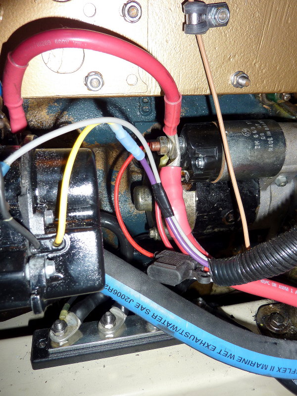
Here's the quick and dirty fix. Try to focus on the red wire between the back of the alternator and the starter post. Simply jump the alternator output to the starter post and disconnect the orange wire. With this jumper the alternator output bypasses the 20+/- feet of teeny tiny 10GA wire and uses the large gauge starter wire to make its way back to the battery switch and then to the battery banks. Minimal voltage drop compared to the 10GA circuit and much less resistance and heat without going through all that small wire and two trailer connectors.
I generally advise running the alternator output directly to the house bank, not to the starter as shown here. You can then install an automatic combining relay (ACR) or an Echo Charger between the banks to charge both simultaneously and automatically. Doing this will remove the potential for fried alternator diodes via the flipping of the battery switch through the OFF position with the motor running. While not 100% necessary it is a good upgrade, and, as I always say, "while you're in there" might as well do it...
Even if you choose not to run the alternator direct to the house bank you are still far safer with the new jumper than you were before.
Bypass The Orange/Red Circuit
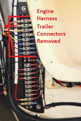
So this is what you are looking for, the trailer connector. Once you find them, there are most often two in there, CUT THEM OUT!!! Replace them with a buss bar and ring terminals or butt splices. These connectors can start fires with high amp loads running through them. They are not designed to have 50+ amps running through them let alone the alt upgrades to 75+ amps I have seen still running though this grossly under designed circuit. This one was clearly melted as you see in the next few photos.
On one boat the engine had been upgraded to the optional 72A alternator and was still running through this circuit and had a battery bank that could take more than 72A of charge current.. Ouch!!
For charging batteries you want minimal voltage drop between the alternator output and the battery bank. For example a stock alternator with a 14.2V set point at 3% voltage drop would have the battery bank seeing about 13.8V. This type of volt drop can chronically undercharge your bank and can lead to premature sulfation and early battery bank death.
One particular boat had 22' of orange and red 10GA wire before it hit the battery switch. Even if we figure the 72A alt will never put out 72A, unless cold, and we base our calculation on just a 60A output, at a 3% volt drop this would require 4GA wire, NOT 10GA. If you want a 2% voltage drop you'd need 2GA wire and this is a far cry from 22' of 10GA wire.....
The Infamous "Trailer Connector"
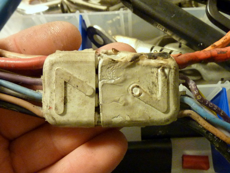
This came off a mid 80's production boat with a "54" series Universal but the early "M" series engines used this set up too. This previous owner of this boat likely had no idea what had been lurking below under all that electrical tape. The current owner was not willing to take any chances with this "new" boat..
I can not stress enough how important it is to bypass the factory charging circuit and remove the trailer connectors on these older engines.
The Melt Down!!
I remember that movie from the 70's and would hate for that to become your boat. Let this image sink in!!!!!
Towering Inferno...??
As you can see these two wires were pretty melted together with jacket blistering and all. A few more deep discharges of this battery bank and this could have been a full blown "burned to the water" situation. This wiring fix for early Universal engines is NOT something to take lightly..
Fused Togerther
Just a little oxidation is all it takes with these cheap connectors to cause resistance in a high amperage circuit. The two pins closest to you are the orange and red wire pins for the charging circuit. Note how clean the low current pins are in the back ground. As I mentioned these connectors are not safe to run this much amperage through.
Just A Little Oxdation
On this particular boat I simply used heat shrink ring terminals and a Blue Sea Buss bar. This connector did not have any high current running through it, as this was on a later Westerbeke, but I still remove the problematic and quirky trailer connectors as I find they are very poorly suited for the marine environment. Even without any high current circuits they still cause issues.
These heat shrink rings create a significantly more reliable and better connection. Once coated with BoeShield, No-Ox-Id Special A, or similar, corrosion protection & electrical gremlins are virtually a non-issue.
So How Do I Remove The Trailer Connectors?
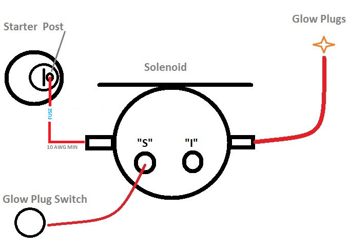
The other high amp circuit on these earlier engines is the glow plug circuit. While the two cylinder engines usually do just fine with a 10GA circuit the three and four cylinder engines can suffer from "slow glow"..
A very quick and easy way to fix this is to insert a simple solenoid into the glow plug circuit. To install this solenoid you simply steal power via a 10GA wire from the starter post. Please be sure to fuse this run as close to the starter post as possible.
You then snip the glow plug wire, add ring terminals, and place the glow plug end on the opposite side of the solenoid from the starter wire and the glow plug switch end goes to the "S" terminal.
Now when you hit the glow plug button a the solenoid closes and creates a direct path between the high current, large gauge, starter wires and the glow plugs. All the glow plug switch has to do is energize the solenoid coil which takes very little current. You are no longer running the glow plugs through 20+ feet of 10GA wire.
Most all newer Universal and Westerbeke engines, with glow plugs, utilize a "preheat solenoid".. You can buy one from Blue Sea and save money. Do be sure that it is ignition protection rated.
What About The Glow Plugs?
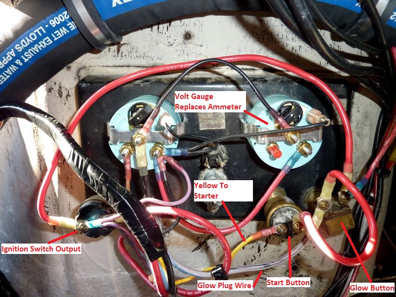
This is one of the simple Universal panels with only a temp gauge and ammeter. They also make them with a tach, oil pressure, water temp & volt gauge. This one has been re-terminated and has been upgraded to a new temp gauge, Teleflex Amega Series, and volt gauge which replaced the ammeter. I installed a Teleflex Amega Series gauge for the volts as well.
As you can see the key switch energizes the glow plug button first. There is then a "series jumper" that ensures the glow plug button is pressed in order to energize the start button. Personally I usually leave this series jumper in place as I have found owners will usually try to bypass the glow and not do it if they think they can get away with it. If you don't use glow, and the motor does not start, you are that much closer to filling your cylinders with water if the seacock was open!
If you feel brave and want to make the start button independent of the glow button simply move the jumper to the incoming side of the glow button, far right side, or jump to the outlet/on side of the key switch, far left. I don't generally advise this and do not even do this on my own vessel as I know I may try and take a short cut some day and it may cost me. While the engine will retain enough heat for a long while to not need "glow" I still like the series circuit, personally.
The yellow wire with red trace is the starter solenoid wire that energizes the starter via making the starter solenoid. It is a tad undersized from the factory so with any resistance in the circuit, from trailer connectors or the in-line fuse holder, this can cause solenoid engagement issues. Once the trailer connectors have been removed, the wire re-terminated and new fuse holder inserted these problems often vanish even with the yellow/red wire. I use ATC fuse holders here, easily accessible, so that in the event of a starter button sticking, this DOES happen, the fuse can be pulled to "disengage" the starter if it is stuck on.
As I mentioned there is an in-line fuse in the yellow/red wire close to the solenoid. This fuse holder is famous for disintegrating and ideally should be replaced when you do this upgrade. If you want to, feel free to run a new wire from the start button to the solenoid, 12GA or 14GA is sufficient, and add a new in-line fuse holder. If access is better elsewhere for this holder, such as at the panel end, then install it there. On most boats behind panel access is tough.
The starter solenoid circuit is a low amp circuit, about 2.3A +/- as measured on the "in-rush" or peak load for the circuit when hitting the starter button and capturing the peak load with a Fluke DC clamp on DVM.. While the yellow wire can certainly handle this amp load it is often the fuse holder or terminations that create enough resistance to cause even a low amp circuit like this some issues.
With some engines I have seen the solenoid circuit wired with 14GA wire and some early ones with 16GA wire. The 16GA wire over a 20' round trip circuit, 10 feet one way, has about 1.6% voltage drop and the 14GA wire is about 1% voltage drop. If we extend the circuit to 20 feet one way, or 40' round trip we are at 3.2% voltage drop on 16GA wire and 2% voltage drop on 14GA wire. These are not bad voltage drop numbers but it you have the ability to re-use one of the other larger wires for this circuit, or run a new one, it will make your solenoid voltage drops even less.
Re-Wired Panel
These are the new Teleflex Amega gauges installed. This panel only had ammeter and temperature. It now has volts and temperature. Teleflex temp, oil & volt gauges will work with the senders on all Universal & Westerbeke engines. Of course voltage is not specific to any boat so that will always work but the oil & temp gauges do work well and these gauges are far less money than buying them direct from Westerbeke/Universal..
Please don't ask what that key switch and hunk of steel in the middle is? Someone added it to this particular boat somewhere along the way. It is not factory and it was long ago disconnected. It does however keep the holes in the panel sealed so I left it.")
Teleflex Amega Gauges
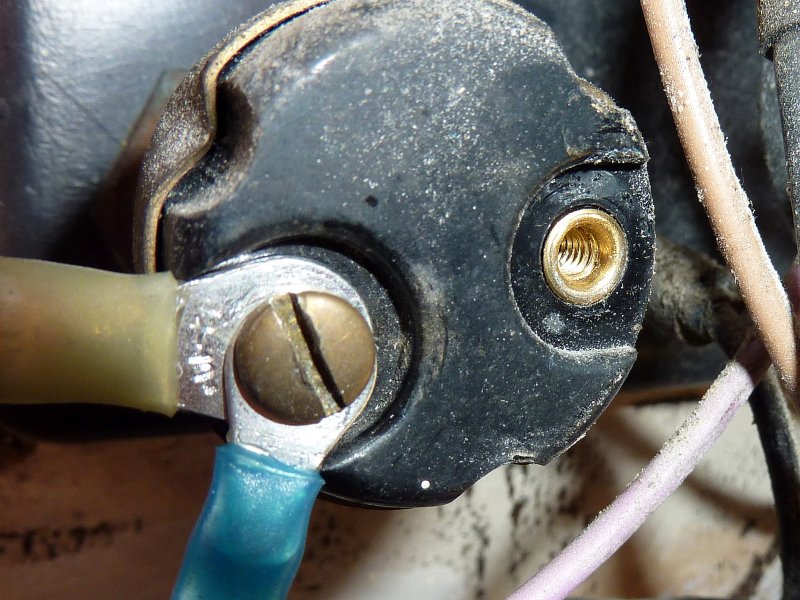
When re-terminating the panel and wires it is a good idea to clean any oxidation from the switches terminals and stripped wires. If the switches are sketchy they should probably be replaced. I use a Dremel and stainless steel brush for this.
Wire Re-terminating
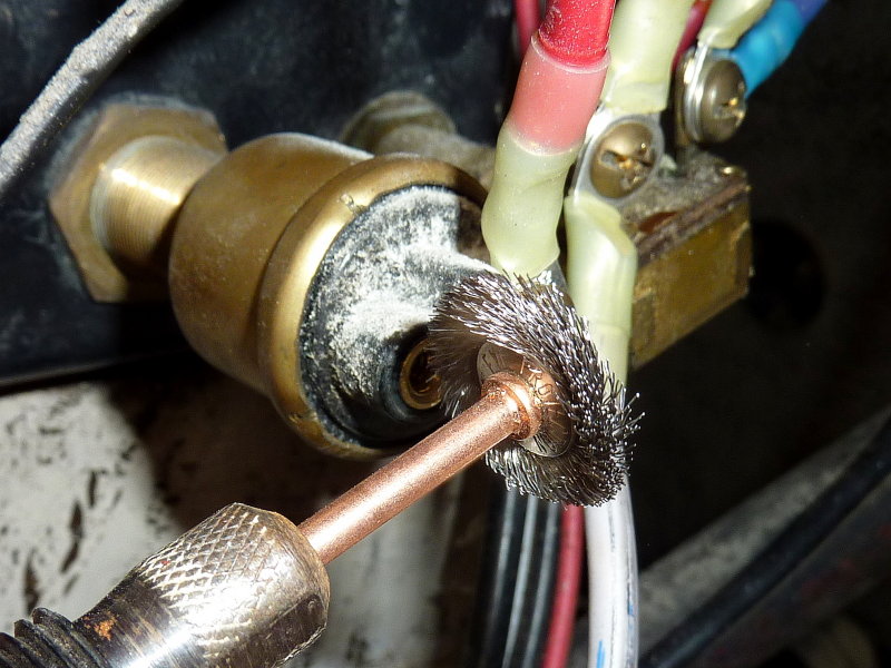
This is the Dremel brush I use, the stainless steel #530 wheel.
Dremel Brush #530
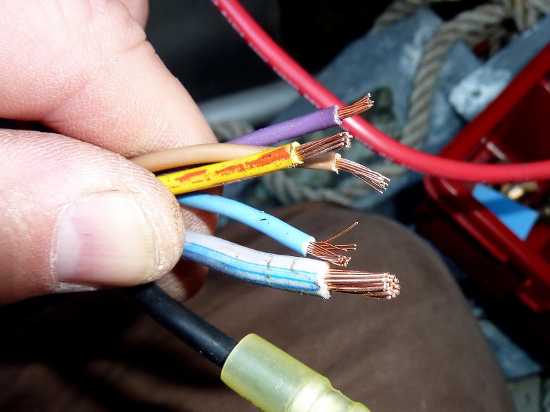
These wires from the factory wiring harness had been fairly oxidized. Cleaning them with the Dremel #530 wheel makes them clean enough for re-termination and creates a good, clean, copper to copper connection. The #530 SS wheel is stiff enough to get into the inner stranding, not just the outer strands. Occasionally you need to manually open or fan the strands out but it takes just a few seconds per wire, that's it. Be sure to get all copper stranding as clean as possible or just replace the wires.
Once clean I use adhesive lined heat shrink crimp on ring terminals. This keeps moisture out and creates a sealed connection.
These Wires Had Been Fairly Oxidized
The factory wiring, with an ammeter in the panel, is flat out dangerous and this really needs to be addressed if it has not yet. It amazes me how many boats are out there still using this unsafe set up.
If you have an ammeter in your panel disconnect the wiring, remove it and jump your alternator 6" over to the starter post with heavy wire. The ammeter can easily be replaced with a volt gauge. Another alternator wiring alternative is to run your alternator direct to the house bank with a fuse or breaker within 7" of the battery and then add a combining relay or Echo Charger..
I have also measured voltage drops of 1.2+ volts or more at just 10A of charge current through these circuits. That means your alt is putting out 14.2V+ and the battery is seeing just 13.0 volts and is being chronically under charged.
Engine Panel With Ammeter = Dangerous
Here's a very crude diagram that shows the alternator charging circuit most often found on these early Universal engines. Universal/Westerbeke Corp later changed this dangerous set up, removed the ammeter and jumped the alternator directly to the starter lug. Interestingly enough many of the Westerbeke engines never used a factory installed ammeter and it was sold as an option unless a builder wanted them that way.
The factory charging circuit leaves the alternator with an orange 10GA wire then most often travels through TWO trailer type connectors to an ammeter at the engine panel. This high amperage current then has to travel all the way back to the battery switch (please note I did not draw the battery switch on this diagram), through more undersized wire, where it finally picks up some larger gauge wire before finally heading to the battery to charge it. These factory circuits often had a 30A fuse in them which was undersized even for some of the alternators shipped on these engines. Owners often put higher amp fuses in or bypassed them all together...
It is not that the ammeter itself is dangerous, unless you upgrade the alternator beyond factory specs, but rather it is the undersized wiring running from the alt and to the batteries that makes this set up dangerous.
The existing alternator charging circuit, with ammeter, runs as far as 25+ feet on some boats before it gets to the battery banks. On most of these panels the entire current of the alternator runs through 10GA wire and a ridiculous trailer type connector that is a huge point of resistance as these boats age. I have pulled many of these connectors and wires out that were literally melted.
With house power demands getting larger and larger and battery banks getting bigger and bigger, and accepting significantly more charging current, these circuits have been known to literally melt down and in some cases catch fire and this is all with stock alternators. I have seen DIY upgrades, & some "pro's", to 100+A alternators still utilizing this circuit. PLEASE DO NOT DO THIS!!!
Early Universal Engines Wiring Harness
Here's the quick and dirty fix. Try to focus on the red wire between the back of the alternator and the starter post. Simply jump the alternator output to the starter post and disconnect the orange wire. With this jumper the alternator output bypasses the 20+/- feet of teeny tiny 10GA wire and uses the large gauge starter wire to make its way back to the battery switch and then to the battery banks. Minimal voltage drop compared to the 10GA circuit and much less resistance and heat without going through all that small wire and two trailer connectors.
I generally advise running the alternator output directly to the house bank, not to the starter as shown here. You can then install an automatic combining relay (ACR) or an Echo Charger between the banks to charge both simultaneously and automatically. Doing this will remove the potential for fried alternator diodes via the flipping of the battery switch through the OFF position with the motor running. While not 100% necessary it is a good upgrade, and, as I always say, "while you're in there" might as well do it...
Even if you choose not to run the alternator direct to the house bank you are still far safer with the new jumper than you were before.
Bypass The Orange/Red Circuit
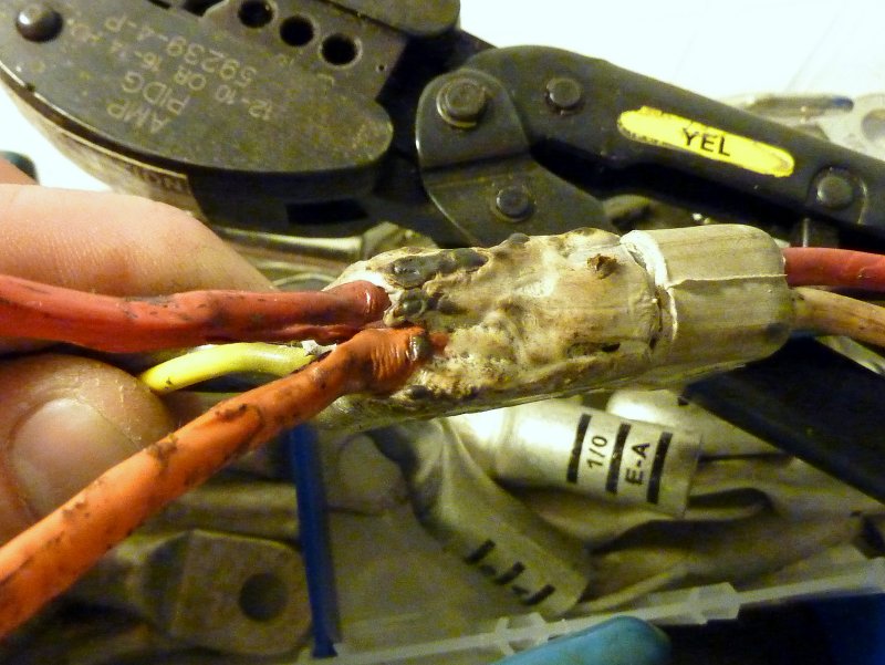
So this is what you are looking for, the trailer connector. Once you find them, there are most often two in there, CUT THEM OUT!!! Replace them with a buss bar and ring terminals or butt splices. These connectors can start fires with high amp loads running through them. They are not designed to have 50+ amps running through them let alone the alt upgrades to 75+ amps I have seen still running though this grossly under designed circuit. This one was clearly melted as you see in the next few photos.
On one boat the engine had been upgraded to the optional 72A alternator and was still running through this circuit and had a battery bank that could take more than 72A of charge current.. Ouch!!
For charging batteries you want minimal voltage drop between the alternator output and the battery bank. For example a stock alternator with a 14.2V set point at 3% voltage drop would have the battery bank seeing about 13.8V. This type of volt drop can chronically undercharge your bank and can lead to premature sulfation and early battery bank death.
One particular boat had 22' of orange and red 10GA wire before it hit the battery switch. Even if we figure the 72A alt will never put out 72A, unless cold, and we base our calculation on just a 60A output, at a 3% volt drop this would require 4GA wire, NOT 10GA. If you want a 2% voltage drop you'd need 2GA wire and this is a far cry from 22' of 10GA wire.....
The Infamous "Trailer Connector"
This came off a mid 80's production boat with a "54" series Universal but the early "M" series engines used this set up too. This previous owner of this boat likely had no idea what had been lurking below under all that electrical tape. The current owner was not willing to take any chances with this "new" boat..
I can not stress enough how important it is to bypass the factory charging circuit and remove the trailer connectors on these older engines.
The Melt Down!!
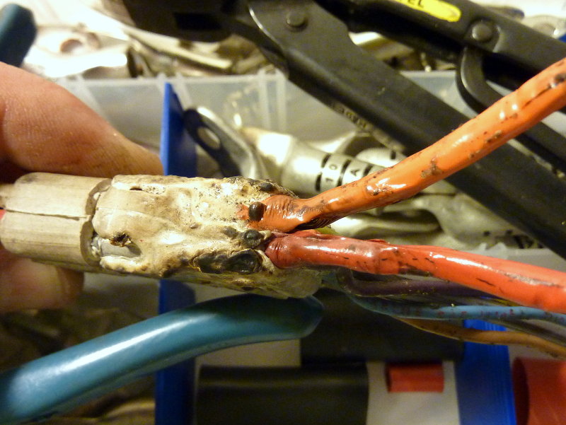
I remember that movie from the 70's and would hate for that to become your boat. Let this image sink in!!!!!
Towering Inferno...??
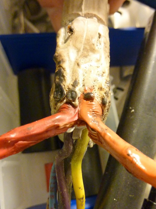
As you can see these two wires were pretty melted together with jacket blistering and all. A few more deep discharges of this battery bank and this could have been a full blown "burned to the water" situation. This wiring fix for early Universal engines is NOT something to take lightly..
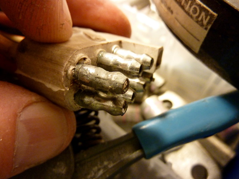
Fused Togerther
Just a little oxidation is all it takes with these cheap connectors to cause resistance in a high amperage circuit. The two pins closest to you are the orange and red wire pins for the charging circuit. Note how clean the low current pins are in the back ground. As I mentioned these connectors are not safe to run this much amperage through.
Just A Little Oxdation
On this particular boat I simply used heat shrink ring terminals and a Blue Sea Buss bar. This connector did not have any high current running through it, as this was on a later Westerbeke, but I still remove the problematic and quirky trailer connectors as I find they are very poorly suited for the marine environment. Even without any high current circuits they still cause issues.
These heat shrink rings create a significantly more reliable and better connection. Once coated with BoeShield, No-Ox-Id Special A, or similar, corrosion protection & electrical gremlins are virtually a non-issue.
So How Do I Remove The Trailer Connectors?
The other high amp circuit on these earlier engines is the glow plug circuit. While the two cylinder engines usually do just fine with a 10GA circuit the three and four cylinder engines can suffer from "slow glow"..
A very quick and easy way to fix this is to insert a simple solenoid into the glow plug circuit. To install this solenoid you simply steal power via a 10GA wire from the starter post. Please be sure to fuse this run as close to the starter post as possible.
You then snip the glow plug wire, add ring terminals, and place the glow plug end on the opposite side of the solenoid from the starter wire and the glow plug switch end goes to the "S" terminal.
Now when you hit the glow plug button a the solenoid closes and creates a direct path between the high current, large gauge, starter wires and the glow plugs. All the glow plug switch has to do is energize the solenoid coil which takes very little current. You are no longer running the glow plugs through 20+ feet of 10GA wire.
Most all newer Universal and Westerbeke engines, with glow plugs, utilize a "preheat solenoid".. You can buy one from Blue Sea and save money. Do be sure that it is ignition protection rated.
What About The Glow Plugs?
This is one of the simple Universal panels with only a temp gauge and ammeter. They also make them with a tach, oil pressure, water temp & volt gauge. This one has been re-terminated and has been upgraded to a new temp gauge, Teleflex Amega Series, and volt gauge which replaced the ammeter. I installed a Teleflex Amega Series gauge for the volts as well.
As you can see the key switch energizes the glow plug button first. There is then a "series jumper" that ensures the glow plug button is pressed in order to energize the start button. Personally I usually leave this series jumper in place as I have found owners will usually try to bypass the glow and not do it if they think they can get away with it. If you don't use glow, and the motor does not start, you are that much closer to filling your cylinders with water if the seacock was open!
If you feel brave and want to make the start button independent of the glow button simply move the jumper to the incoming side of the glow button, far right side, or jump to the outlet/on side of the key switch, far left. I don't generally advise this and do not even do this on my own vessel as I know I may try and take a short cut some day and it may cost me. While the engine will retain enough heat for a long while to not need "glow" I still like the series circuit, personally.
The yellow wire with red trace is the starter solenoid wire that energizes the starter via making the starter solenoid. It is a tad undersized from the factory so with any resistance in the circuit, from trailer connectors or the in-line fuse holder, this can cause solenoid engagement issues. Once the trailer connectors have been removed, the wire re-terminated and new fuse holder inserted these problems often vanish even with the yellow/red wire. I use ATC fuse holders here, easily accessible, so that in the event of a starter button sticking, this DOES happen, the fuse can be pulled to "disengage" the starter if it is stuck on.
As I mentioned there is an in-line fuse in the yellow/red wire close to the solenoid. This fuse holder is famous for disintegrating and ideally should be replaced when you do this upgrade. If you want to, feel free to run a new wire from the start button to the solenoid, 12GA or 14GA is sufficient, and add a new in-line fuse holder. If access is better elsewhere for this holder, such as at the panel end, then install it there. On most boats behind panel access is tough.
The starter solenoid circuit is a low amp circuit, about 2.3A +/- as measured on the "in-rush" or peak load for the circuit when hitting the starter button and capturing the peak load with a Fluke DC clamp on DVM.. While the yellow wire can certainly handle this amp load it is often the fuse holder or terminations that create enough resistance to cause even a low amp circuit like this some issues.
With some engines I have seen the solenoid circuit wired with 14GA wire and some early ones with 16GA wire. The 16GA wire over a 20' round trip circuit, 10 feet one way, has about 1.6% voltage drop and the 14GA wire is about 1% voltage drop. If we extend the circuit to 20 feet one way, or 40' round trip we are at 3.2% voltage drop on 16GA wire and 2% voltage drop on 14GA wire. These are not bad voltage drop numbers but it you have the ability to re-use one of the other larger wires for this circuit, or run a new one, it will make your solenoid voltage drops even less.
Re-Wired Panel
These are the new Teleflex Amega gauges installed. This panel only had ammeter and temperature. It now has volts and temperature. Teleflex temp, oil & volt gauges will work with the senders on all Universal & Westerbeke engines. Of course voltage is not specific to any boat so that will always work but the oil & temp gauges do work well and these gauges are far less money than buying them direct from Westerbeke/Universal..
Please don't ask what that key switch and hunk of steel in the middle is? Someone added it to this particular boat somewhere along the way. It is not factory and it was long ago disconnected. It does however keep the holes in the panel sealed so I left it.
Teleflex Amega Gauges
When re-terminating the panel and wires it is a good idea to clean any oxidation from the switches terminals and stripped wires. If the switches are sketchy they should probably be replaced. I use a Dremel and stainless steel brush for this.
Wire Re-terminating
This is the Dremel brush I use, the stainless steel #530 wheel.
Dremel Brush #530
These wires from the factory wiring harness had been fairly oxidized. Cleaning them with the Dremel #530 wheel makes them clean enough for re-termination and creates a good, clean, copper to copper connection. The #530 SS wheel is stiff enough to get into the inner stranding, not just the outer strands. Occasionally you need to manually open or fan the strands out but it takes just a few seconds per wire, that's it. Be sure to get all copper stranding as clean as possible or just replace the wires.
Once clean I use adhesive lined heat shrink crimp on ring terminals. This keeps moisture out and creates a sealed connection.
These Wires Had Been Fairly Oxidized


