Hello Maine Sail and others,
Happy New Year! 2015 is setup to be exciting for us as we plan to head out cruising in about 10 months.
Part of our cruising prep is adding solar to our boat. Here is my plan. I would appreciate any thoughts or comments you may have.
Here is a quick summary of what I have been planning:
1) Living on the hook I am estimating we will use between 50-125 amp hours per day;
2) We are willing to run our diesel engine up to 1.5 hours a day allowing are alternator to generate about 65 amp hours, plus producing hot water as a by-product;
3) That would mean that we would want to generate about 50 amp hours of solar power a day;
4) Given that we are going in a small boat, efficiency is important, so we would like get the increased 15-20% efficiency you get from an MPPT controller over a PWM controller;
5) We may decide to add a watermaker to our boat and would like the ability to expand our solar array to offset some of that power consumption. So that would mean we would want to size certain aspects to allow for the easy upgrade in the future;
6) We like the aspect of the semi-flexible panels since they would allow us to disassemble and store the panels more easily in the event of a storm, and;
7) We are NOT independently wealthy and are trying to do this cruise in a very cost effective manner, so we can’t afford to splurge on the best available product for every component.
All that being said, here is what I have come up with for the our solar array:
- Two (2) 100 watt semi-flexible solar panels mounted on our bimini;
- A 30 amp MPPT controller with a remote panel, and;
- An ability to expand the system by added two (2) 100 watt semi-flexible solar panels on the life lines or on deck.
I am planning to go with the Renogy semi-flexible panels. I can fit two of the 100-watt panels without having them cross any bows for the bimini. I plan to mount the panels with velcro like Maine Sail has shown before. I know I need to stiffen the bimini frame to do this and will get that completed before I put the panels up there.
I know one downside to the cheaper panels seems to be consistency. From reading reviews and recommendations, mainly from Maine Sail, on the sailing forums it appears that the best practice is to do some side by side testing as soon as you get them in. To do this I will make a 2×4 A frame that I can temporarily mount the panels on. I will then hook up the each panel separately to the charge controller and a battery. I will let each panel run for an hour and record the performance to make sure they are in the same ball park. I plan to record the starting, mid charge and ending volts and amps at the battery and the charge controller. If the results from each panel are not within the expected range I will send them back until I get a set I am comfortable with. This is another good reason to go with the Renogy because they are Amazon Prime eligible and that will help if I need to send them back.
As I stated above, I want to go with an oversized MPPT charge controller. I looked at the Rogue MPT-3048, MidNite KID, TriStar 30, TriStar 40 and Blue Sky SB3024iL. This list primarily came from an article on the Compass Marine site about adding a small panel plus some recommendations I got from cruisers. I briefly considered some lesser brands such as the Renogy but decided that this piece was important enough to not mess around with off-brands.
Some of my key concerns were that I wanted flexibility to change the charge profile, the ability to equalize, a temp sensor and a remote panel. I plan to mount the controller in the stern compartment near the shore power charger and holding tank. I am concerned about the heat aspect. I don’t want to mount this unit in the cabin and have it dissipate heat into the cabin while we are in the tropics. I would also like some secondary ability to know what is going into the batteries besides the our Victron Battery Monitor.
In the end I found that the Rogue MPT-3048 had the best balance of options for the cost. It comes standard with a temp sensor and voltage sensors. The cost for adding the remote panel wasn’t bad. It didn’t hurt that it was among the cheapest. Still talking over $400 when all is said and done.
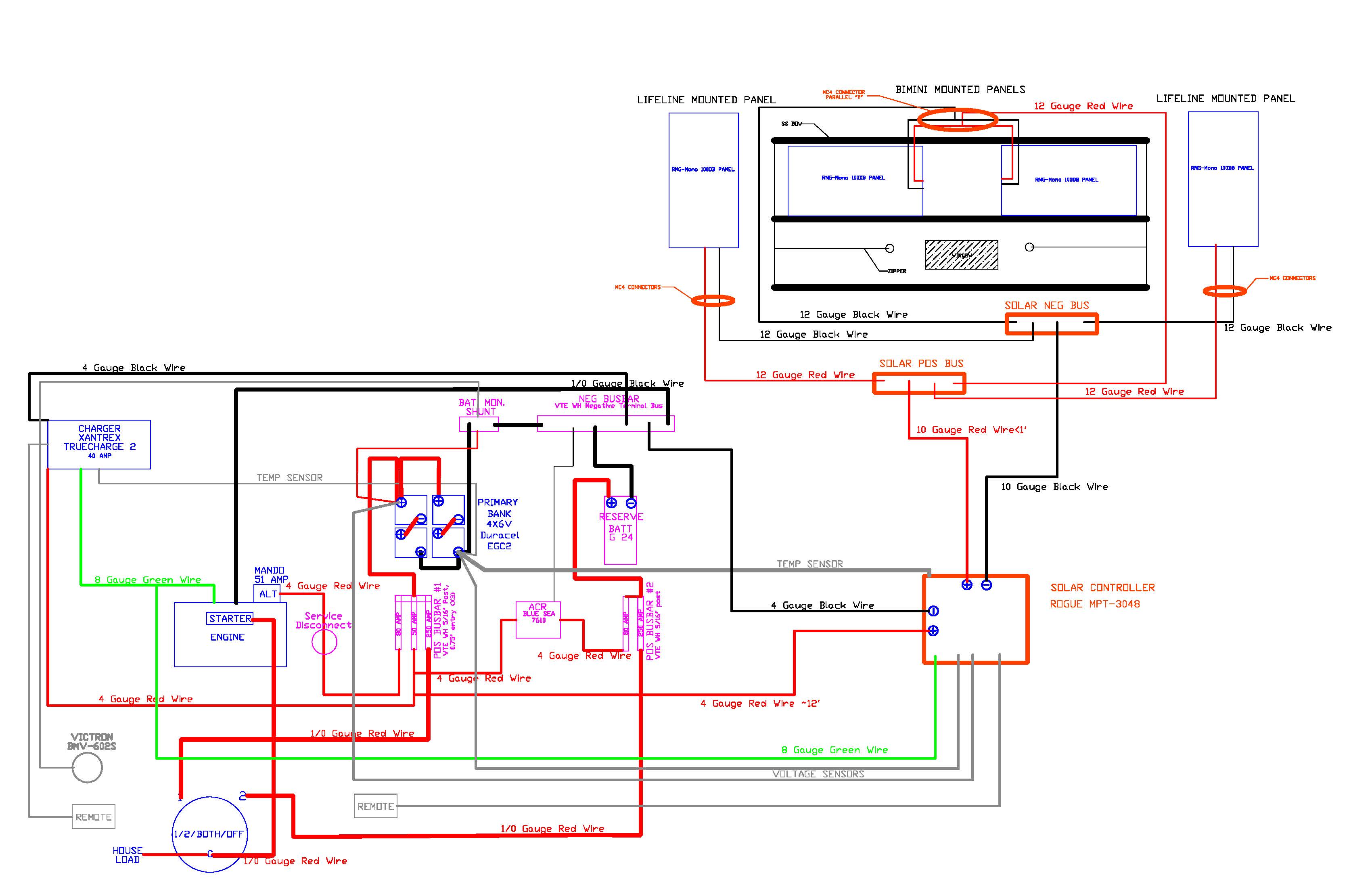
I plan to wire the two panels on the bimini in parallel. From what I have read, you want to wire solar panels on a boat in parallel as that handles partial shading on a portion of one panel the best. If they are in series shading would degrees the output of the panels more. I am going to use the MC4 connectors for the panel wiring. This seems to give a good connection that can be disconnected easily when needed, yet another good Compass Marine article on this subject. I also plan to use the Renogy MC4 branch connectors to make the parallel connection at the bimini. I like how you can choose which side to make the male and which to make the female so you can make it dummy proof so you can’t connect them in reverse polarity. The Renogy panels come pre-wired this way.
Here is my proposed wiring diagram. Getting a little busy and I might need to find a way to clean it up a little. I am attaching a PDF as well in case anyone wants to add comments on my wiring.
Please let me know what you think.
Thanks,
Jesse
Happy New Year! 2015 is setup to be exciting for us as we plan to head out cruising in about 10 months.
Part of our cruising prep is adding solar to our boat. Here is my plan. I would appreciate any thoughts or comments you may have.
Here is a quick summary of what I have been planning:
1) Living on the hook I am estimating we will use between 50-125 amp hours per day;
2) We are willing to run our diesel engine up to 1.5 hours a day allowing are alternator to generate about 65 amp hours, plus producing hot water as a by-product;
3) That would mean that we would want to generate about 50 amp hours of solar power a day;
4) Given that we are going in a small boat, efficiency is important, so we would like get the increased 15-20% efficiency you get from an MPPT controller over a PWM controller;
5) We may decide to add a watermaker to our boat and would like the ability to expand our solar array to offset some of that power consumption. So that would mean we would want to size certain aspects to allow for the easy upgrade in the future;
6) We like the aspect of the semi-flexible panels since they would allow us to disassemble and store the panels more easily in the event of a storm, and;
7) We are NOT independently wealthy and are trying to do this cruise in a very cost effective manner, so we can’t afford to splurge on the best available product for every component.
All that being said, here is what I have come up with for the our solar array:
- Two (2) 100 watt semi-flexible solar panels mounted on our bimini;
- A 30 amp MPPT controller with a remote panel, and;
- An ability to expand the system by added two (2) 100 watt semi-flexible solar panels on the life lines or on deck.
I am planning to go with the Renogy semi-flexible panels. I can fit two of the 100-watt panels without having them cross any bows for the bimini. I plan to mount the panels with velcro like Maine Sail has shown before. I know I need to stiffen the bimini frame to do this and will get that completed before I put the panels up there.
I know one downside to the cheaper panels seems to be consistency. From reading reviews and recommendations, mainly from Maine Sail, on the sailing forums it appears that the best practice is to do some side by side testing as soon as you get them in. To do this I will make a 2×4 A frame that I can temporarily mount the panels on. I will then hook up the each panel separately to the charge controller and a battery. I will let each panel run for an hour and record the performance to make sure they are in the same ball park. I plan to record the starting, mid charge and ending volts and amps at the battery and the charge controller. If the results from each panel are not within the expected range I will send them back until I get a set I am comfortable with. This is another good reason to go with the Renogy because they are Amazon Prime eligible and that will help if I need to send them back.
As I stated above, I want to go with an oversized MPPT charge controller. I looked at the Rogue MPT-3048, MidNite KID, TriStar 30, TriStar 40 and Blue Sky SB3024iL. This list primarily came from an article on the Compass Marine site about adding a small panel plus some recommendations I got from cruisers. I briefly considered some lesser brands such as the Renogy but decided that this piece was important enough to not mess around with off-brands.
Some of my key concerns were that I wanted flexibility to change the charge profile, the ability to equalize, a temp sensor and a remote panel. I plan to mount the controller in the stern compartment near the shore power charger and holding tank. I am concerned about the heat aspect. I don’t want to mount this unit in the cabin and have it dissipate heat into the cabin while we are in the tropics. I would also like some secondary ability to know what is going into the batteries besides the our Victron Battery Monitor.
In the end I found that the Rogue MPT-3048 had the best balance of options for the cost. It comes standard with a temp sensor and voltage sensors. The cost for adding the remote panel wasn’t bad. It didn’t hurt that it was among the cheapest. Still talking over $400 when all is said and done.
I plan to wire the two panels on the bimini in parallel. From what I have read, you want to wire solar panels on a boat in parallel as that handles partial shading on a portion of one panel the best. If they are in series shading would degrees the output of the panels more. I am going to use the MC4 connectors for the panel wiring. This seems to give a good connection that can be disconnected easily when needed, yet another good Compass Marine article on this subject. I also plan to use the Renogy MC4 branch connectors to make the parallel connection at the bimini. I like how you can choose which side to make the male and which to make the female so you can make it dummy proof so you can’t connect them in reverse polarity. The Renogy panels come pre-wired this way.
Here is my proposed wiring diagram. Getting a little busy and I might need to find a way to clean it up a little. I am attaching a PDF as well in case anyone wants to add comments on my wiring.
Please let me know what you think.
Thanks,
Jesse