
We took a deep dive on Keel -- but for those contemplating replacing and manipulating your keel hanger brackets/ pin and surrounding surfaces: I've outlined my progress migrating from the old style assembly (1973) to the new (CD purchased).
Step 1) Evaluate your existing circumstances. This is literally day 1 of S/V Mary Anne's retrofit-- first thing I did after bringing her home was to take a look at the keel.

Don't let the 35 foot test fool you! Yes-- it looks pretty darn good from just a few feet away, but get in there and really look-- It's rusted through and through and the classic "hole hogging" has begun / continues.

An even closer examination of the Eye Bolt is more disturbing (never-mind the compromised keel cable head) :
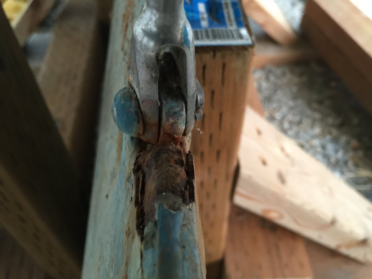
You can see that the keel is literally rusting from the inside out-- everything under whatever the blue paint may have been is nothing more than a rust placebo-- it made someone feel better while the metal continues to degrade.
Step 1A) Evaluate wear points on the bracket assembly. This was taken the same day once the keel was down-- early style square hangers with classic (but not overly horrific) pin wear (shiny area).
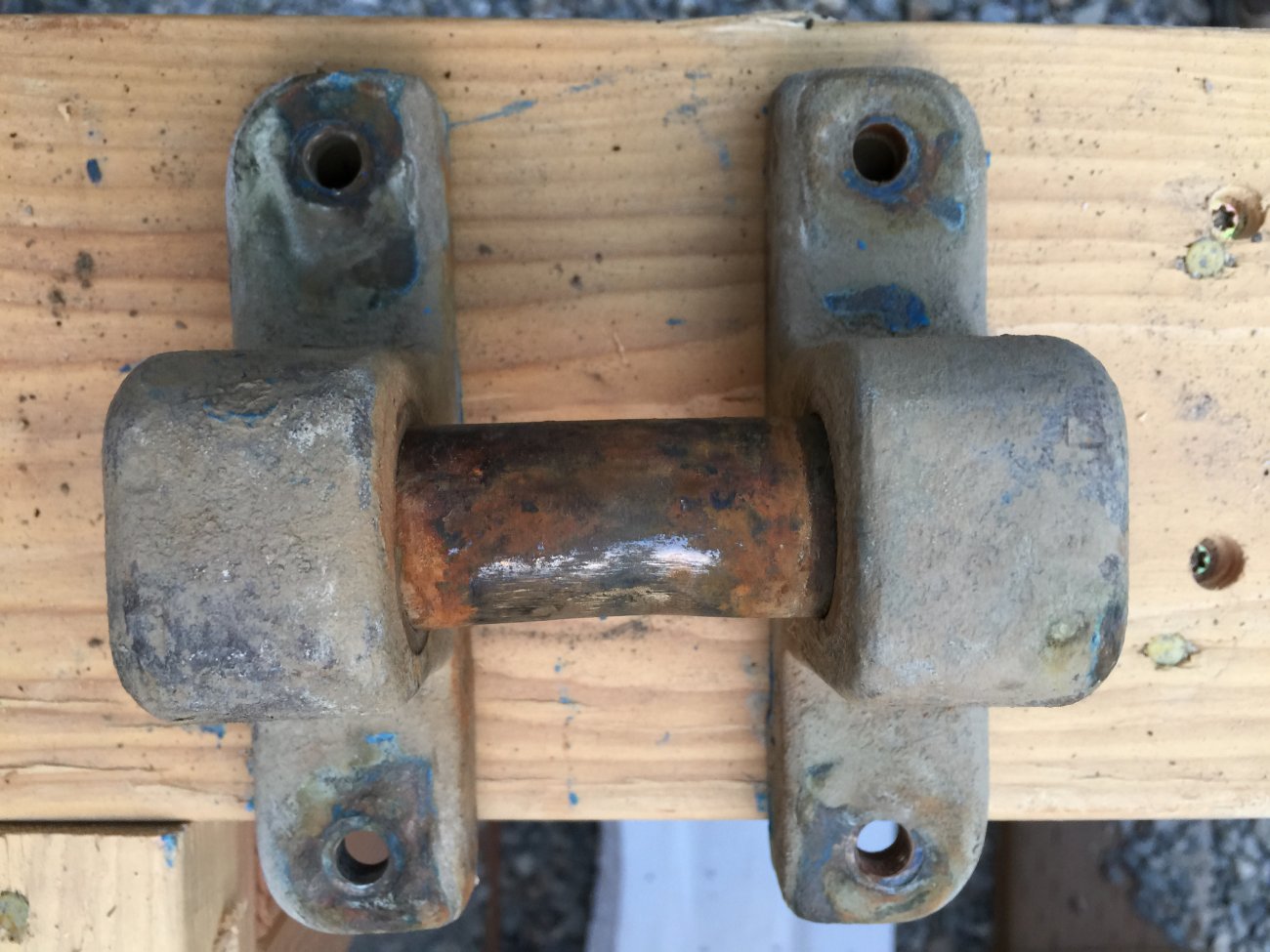
Replete with spider webs and sycamore fluff-- weldments are intact and thankfully were not seized and the bolts cleared without issue. Note the depth of the housing-- significantly different than that of the new style hangers and what you can purchase through CD.
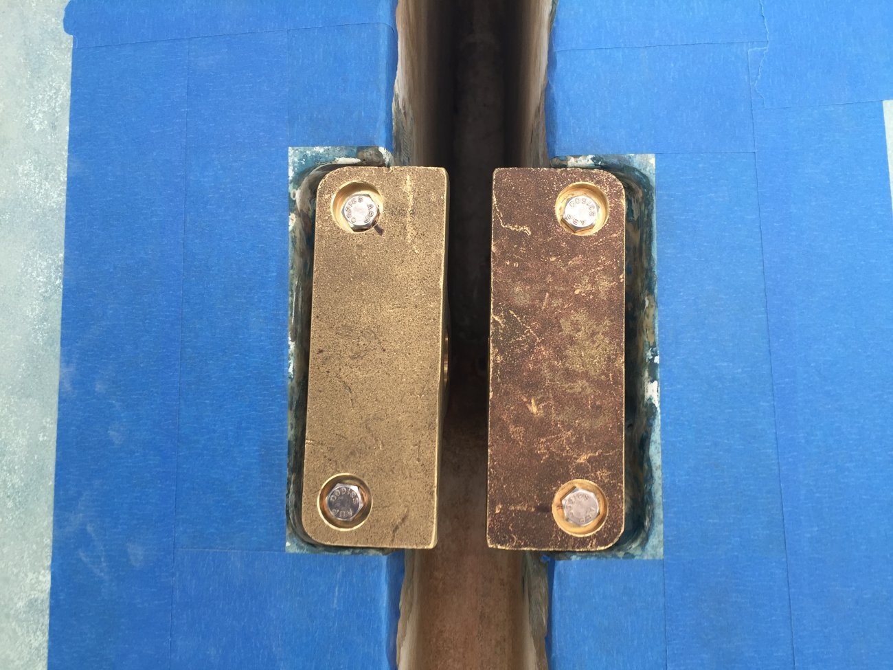
Step 2) New brackets in hand-- dry fit dry fit dry fit. The new brackets will be too wide by design-- the pin over length so you can measure and cut to fit. Blue Painters tape has been applied around the assembly prior to the epoxy application.
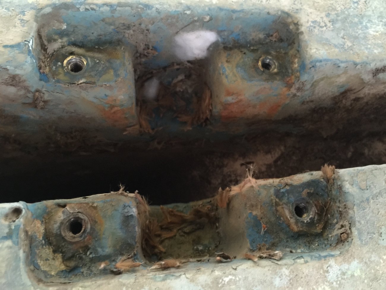
It looks decent at first glance, but again closer inspection will reveal that this is the beginning of a conundrum-- so much for the easy button.
Step 3) I start measuring for width-- the keel is about 1.5 inches wide, I need to cut both hangers symmetrically--the thought of symmetry and the keel being square relative to the trunk exposes the mess.
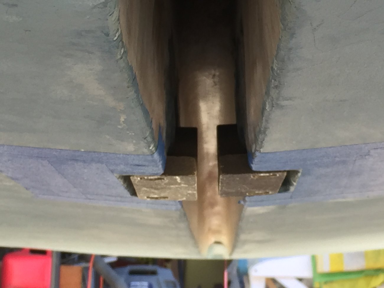
A longer perspective shows that the fit of the new hanger in the pocket is loose at best (technical term: acute gaposis) but even more concerning:
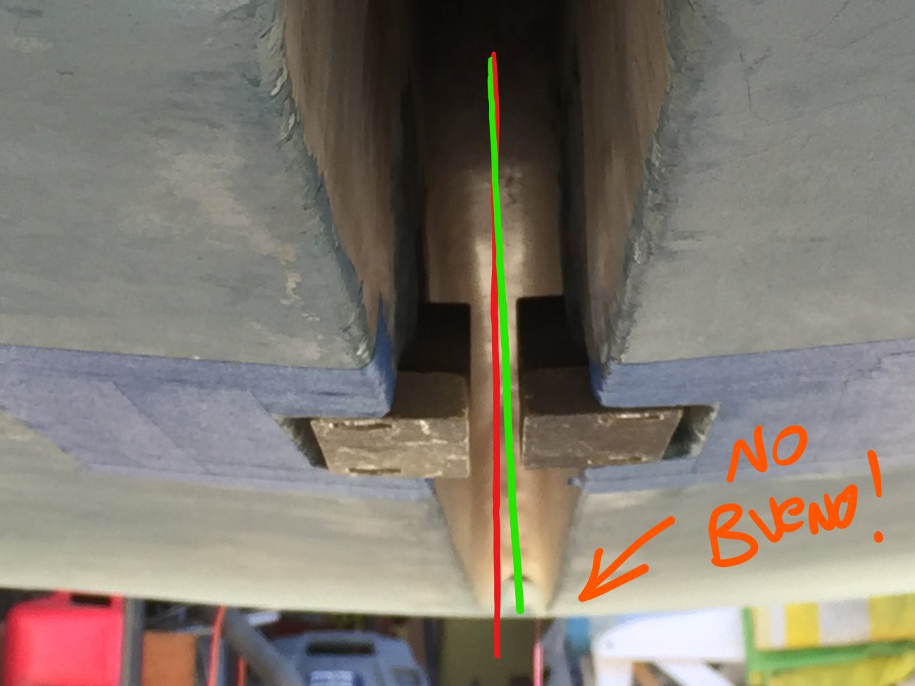
No Bueno indeed-- I drew these lay lines by hand on the image-- but you can see the green represents the keel trunk and the red represents the face of the hanger brackets. Over the course of the full keel-- the differential isn't just sloppy, it is a disaster in the making. At this point I'm nothing short of befuddled, you should be able to bring two square faces into parallel..... now what???
Standby for part 2")
Step 1) Evaluate your existing circumstances. This is literally day 1 of S/V Mary Anne's retrofit-- first thing I did after bringing her home was to take a look at the keel.
Don't let the 35 foot test fool you! Yes-- it looks pretty darn good from just a few feet away, but get in there and really look-- It's rusted through and through and the classic "hole hogging" has begun / continues.
An even closer examination of the Eye Bolt is more disturbing (never-mind the compromised keel cable head) :
You can see that the keel is literally rusting from the inside out-- everything under whatever the blue paint may have been is nothing more than a rust placebo-- it made someone feel better while the metal continues to degrade.
Step 1A) Evaluate wear points on the bracket assembly. This was taken the same day once the keel was down-- early style square hangers with classic (but not overly horrific) pin wear (shiny area).
Replete with spider webs and sycamore fluff-- weldments are intact and thankfully were not seized and the bolts cleared without issue. Note the depth of the housing-- significantly different than that of the new style hangers and what you can purchase through CD.
Step 2) New brackets in hand-- dry fit dry fit dry fit. The new brackets will be too wide by design-- the pin over length so you can measure and cut to fit. Blue Painters tape has been applied around the assembly prior to the epoxy application.
It looks decent at first glance, but again closer inspection will reveal that this is the beginning of a conundrum-- so much for the easy button.
Step 3) I start measuring for width-- the keel is about 1.5 inches wide, I need to cut both hangers symmetrically--the thought of symmetry and the keel being square relative to the trunk exposes the mess.
A longer perspective shows that the fit of the new hanger in the pocket is loose at best (technical term: acute gaposis) but even more concerning:
No Bueno indeed-- I drew these lay lines by hand on the image-- but you can see the green represents the keel trunk and the red represents the face of the hanger brackets. Over the course of the full keel-- the differential isn't just sloppy, it is a disaster in the making. At this point I'm nothing short of befuddled, you should be able to bring two square faces into parallel..... now what???
Standby for part 2
Last edited: