I use a terminal strip, so i can make the change there, and that was useful when I had multiple panels on a controller. Now I have a controller for each panel.I have 2 switches to change the panels from series to parallel. If a panel goes bad, switch to parallel to use just the one good one.
Solar.... getting volts but no amps????
- Thread starter NYSail
- Start date
A helpful way of thinking about electric circuits is to use a water system as an analogy.There is voltage going to the battery. Today I will turn off all loads and see what is coming through in regards to amps.
Thanks!
Greg
Voltage would be analogous to the pressure in a pipe.
Amperage would be analogous to the flow of water in the pipe.
Resistance is the diameter of the pipe.
The pressure in a pipe exists regards of the fact that water may be flowing or not. Same is true for voltage. The voltage is the pressure you solar panel is able to provide to your battery. And the battery can be thought of as being analogous to a water tower that stores water at a specific pressure (height) or maybe a bladder tank is also a good analogy for a battery. When you panel is trying to charge the battery, you should think of it as analogous to pumping water into a bladder tank. If the tank is empty, there is no back pressure and the flow (current) will be high. As the tank starts to fill, the back pressure from the tank will slow the current.
In you charging system, you will see the same thing. As your battery gets close to "full" the amperage will slow
Ok..... so spoke with the tech and he said sounds like a polarity issue. I checked all connections and everything is correct, but again battery monitor just doesn’t seem right. See the following pictures measuring amps and volts:
1- solar charger
2- meter on battery
3- batter monitor
Do t know if they attached in order...... what does this show?
Thanks
Greg
1- solar charger
2- meter on battery
3- batter monitor
Do t know if they attached in order...... what does this show?
Thanks
Greg
Attachments
-
 23.7 KB Views: 145
 -
 31.1 KB Views: 172
 -
 32.1 KB Views: 151
 -
 24.5 KB Views: 166
 -
 15.2 KB Views: 154
 -
 15.7 KB Views: 175
Yep and the monitor is showing diminishing soc. However with solar turned off and alt running all seems fine.Is the Xantrex monitor showing negative 5.1A? Doesn't make sense to me.
The solar controller was reading very close to that but it was a + reading? To quote Bugs Bunny- “Screwey, ain’t it?”Yep and the monitor is showing diminishing soc. However with solar turned off and alt running all seems fine.
On the battery where the solar attaches.......Where was the multimeter connected when you measured 5.25A?
I presume you mean inline between the positive battery post and the red solar lead? Because the black solar lead goes to the load side of the shunt, not the battery, correct? Which lead from the multimeter was connected to the battery, and which was connected to the panel lead?On the battery where the solar attaches.......
Both leads from multimeter were on the battery where panel leads eventually lead. Neg comes directly from controller to load side of shunt red comes from controller to a fuse then to battery
Attachments
-
 18.7 KB Views: 149
The way you drew the picture has the negative lead coming into the battery side of the shunt, not the load side. If that’s how it’s wired then there’s your problem.
.
I mean the picture where the multimeter is measuring amps, not volts. If the multimeter were set to amps and connected to opposite battery terminals I’m afraid things would’ve been much more “exciting”Both leads from multimeter were on the battery where panel leads eventually lead.
.
The way you drew the picture has the negative lead coming into the battery side of the shunt, not the load side. If that’s how it’s wired then there’s your problem.
So what if I just took the negative lead from the solar controller and connected it directly to the battery? Again I am no dc genius but currently it appears to be connected just as my alt is connected and that seems to be just fine? And this alone would affect the monitors reading on amps only and not volts?The way you drew the picture has the negative lead coming into the battery side of the shunt, not the load side. If that’s how it’s wired then there’s your problem.
Once again thanks for all your input and patience.
Greg
I mean the picture where the multimeter is measuring amps, not volts. If the multimeter were set to amps and connected to opposite battery terminals I’m afraid things would’ve been much more “exciting”
.I think we’re getting closer.
I think you’re thinking of the shunt as a bus, which it is not. On a bus all posts are electrically equivalent. A shunt is a very high capacity, low resistance resistor. You need to have all loads and charging sources on one end of that resistor, and the battery on the other. I’m guessing your alternator is on the load post of the shunt, and you now have the solar on the battery side. Put the solar on the same physical post as the alternator input and then they should both read correctly.
According to the picture what you’ve done is electrically equivalent to putting the negative solar lead straight into the battery. You’ll charge the battery just fine, but the monitor doesn’t know about it, because the charge current doesn’t traverse the shunt.So what if I just took the negative lead from the solar controller and connected it directly to the battery?
Yes, it would. The monitor reads the battery voltage by measuring the potential between the positive and negative battery posts. So that will be accurate. It measures amps by measuring the the potential from one side of the shunt to another. If the charge current doesn’t go through the shunt then the monitor won’t see that current, so the amps will be inaccurate.And this alone would affect the monitors reading on amps only and not volts?
I think you’re thinking of the shunt as a bus, which it is not. On a bus all posts are electrically equivalent. A shunt is a very high capacity, low resistance resistor. You need to have all loads and charging sources on one end of that resistor, and the battery on the other. I’m guessing your alternator is on the load post of the shunt, and you now have the solar on the battery side. Put the solar on the same physical post as the alternator input and then they should both read correctly.
This is the correct way to wire a shunt in the system. Note that the current passes through the shunt and is monitored after the it passes. There is a very low value resistor in the shunt and the monitor senses the voltage drop. The shunt allows high currents to pass without damage. This will monitor the panel's current flow only, not the flow to the house banks or starter banks.
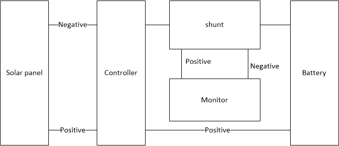
Note: If you get a negative value on the monitor (i.e. -5.53aH) then reverse the leads from the monitor to the shunt.
Note: The monitor is nothing more than a volt meter reading the voltage drop across the shunt resistor.
Note: If you get a negative value on the monitor (i.e. -5.53aH) then reverse the leads from the monitor to the shunt.
Note: The monitor is nothing more than a volt meter reading the voltage drop across the shunt resistor.
Light bulb!! Guess what...... problem solved!I think we’re getting closer.
According to the picture what you’ve done is electrically equivalent to putting the negative solar lead straight into the battery. You’ll charge the battery just fine, but the monitor doesn’t know about it, because the charge current doesn’t traverse the shunt.
Yes, it would. The monitor reads the battery voltage by measuring the potential between the positive and negative battery posts. So that will be accurate. It measures amps by measuring the the potential from one side of the shunt to another. If the charge current doesn’t go through the shunt then the monitor won’t see that current, so the amps will be inaccurate.
I think you’re thinking of the shunt as a bus, which it is not. On a bus all posts are electrically equivalent. A shunt is a very high capacity, low resistance resistor. You need to have all loads and charging sources on one end of that resistor, and the battery on the other. I’m guessing your alternator is on the load post of the shunt, and you now have the solar on the battery side. Put the solar on the same physical post as the alternator input and then they should both read correctly.
Again the wonders (and patience) of this group is invaluable!
Thanks!!!!!!
Greg
My theory is, if it USES electricity or MAKES it, it has to pass through the neg shunt.Light bulb!! Guess what...... problem solved! Again the wonders (and patience) of this group is invaluable! Greg