I've read MS's post (Wiring & Installing A Battery Monitor) a few times and did my best to search, but I think I found conflicting info, so apologies for the basic question. I have a 2 bank set up and am re-wiring a Link 2000 to it. Does the engine ground cable (the starting bat - bank 2--is connected to the engine, and the engine ground cable then to my negative bus bar) get connected to the actual shunt (load side) or can it stay on the negative bus bar? Or does it not matter? Thx!
shunt wiring for engine ground?
- Thread starter wsconner
- Start date
All of the grounds can be connected to the bus bar so long as the bus bar is rated to accept the maximum load. To the extent possible the ground wires on the engine should be attached at the same point, this grounds the engine and connects all the grounds but does not put the engine into the ground circuit.
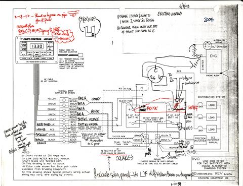
Batt Bank #1 to shunt post for that bank, Batt Bank #2 to the other shunt post, then from one of the posts on the other side of the shunt to the neg distribution post (NDP) and then to the engine. My Link 2000 manual has a wiring diagram in the Installation and Wiring section.
Look at the little hand sketch, middle top, shows which post has the one wire from the shunt to the NDP.
Look at the little hand sketch, middle top, shows which post has the one wire from the shunt to the NDP.
Last edited:

Thanks for replies.. realized I might not have been specific enough with my question. I was basically trying to figure out the ease of wiring the Link 2000 to both banks, given the starter battery (bank 2) is located aft in the cockpit and I only have one negative cable which runs to the engine, and then to my negative bus bar. So I think the diagram confirms that I'd need to run another cable directly from the bank 2 battery to the shunt (and not re-use the cable that goes to the engine, then to my bus bar). I think that is what I was really trying to ask.. can the negative cable from battery be "interrupted" by the ground connection at engine, before being connected to the Bat2 negative shunt terminal?
My primary need is to monitor my house bank (three 31agms) and I can jump the wires so that the unit only sees one bank.
My primary need is to monitor my house bank (three 31agms) and I can jump the wires so that the unit only sees one bank.
Yes. The negative cable from the battery can run to the engine block. The negative cable from the house bank negative bus bar can then run to the same point on the engine block. In a sense, the engine block serves as another negative bus bar.can the negative cable from battery be "interrupted" by the ground connection at engine, before being connected to the Bat2 negative shunt terminal?
It is a little more complicated than just "jump the wires." Placing the three batteries in parallel will yield 3 times the amp hours at 12 v. The batteries should be of same type, age, and condition. Ideally all done when new and with all batteries from the same manufacturing lot. In effect the 3 batteries become one big battery. The cables should be run negative to negative, positive to positive. The place mistakes are made is connecting the bank to the house system. The positive cable to the battery switch comes off one end of the parallel bank and the negative cable comes from the negative terminal on the battery at the other end of the parallel bank. If these cables come from the same battery you will only use the first battery, the rest of the batteries will not be used. Making the connections at opposite ends will engage all 3 batteries and draw them down equally.My primary need is to monitor my house bank (three 31agms) and I can jump the wires so that the unit only sees one bank.
Ok, thanks, yes.. my Bank 1 (House) is three Northstar's wired in parallel for ~315amps. I was actually talking about jumping the wires for the Link 2000 module. Manual says you can combine the Bat 2 (my starter and 2nd "bank") sensing wire (violet) to the Bank 1 sensing wire (blue) so the unit looks at both banks as a single bank. Stu's diagram in previous post shows that wiring in more detail. My bank 2 (starter battery) is configured to charge with an ACR per MS's excellence guidance here, so it's really just an auxiliary power source at this point.
I'm not that familiar with the link systems however, I would be disinclined to measure the 2 banks as one, primarily because if the monitor indicates a problem, you don't know which bank has the problem without messing with the wiring. The house bank is the most important and the one most likely to be undercharged or have an issue, so I want to closely monitor that bank. The starting bank gets charged quickly and is lightly used, so the likelihood of failure is lower and the house bank can be used to start the engine.
the way the Link 2000 needs to work is it has two sensors..one for each bank being monitored. If you don't have two banks connected, which I don't now plan to do, you need to make the Link unit think there is only one bank being monitored. So the instructions call for "jumping" the sensor wire for bank 2 to bank 1, so it thinks there are two banks but it's really only one.
I know someone will say "stop messing with the old tech", and I'm tempted to just buy the SG200, but I've learned a lot reading the Link manual and it's already installed on the boat, so just needed to be wired up. So I figured I'd play with it for a season and then when I do move on to modern tech I'l probably appreciate it more...")
I know someone will say "stop messing with the old tech", and I'm tempted to just buy the SG200, but I've learned a lot reading the Link manual and it's already installed on the boat, so just needed to be wired up. So I figured I'd play with it for a season and then when I do move on to modern tech I'l probably appreciate it more...
ws, if you don't want to run a separate individual negative wire from Batt #2 "through" the shunt, then the easiest thing to do is not bother at all. Use the Link for only your house bank, or combine them all through the shunt into one bank, and program accordingly.
You might be interested in this: (parallel to MS's batt monitor article)
For everyone installing a battery monitor: The "Gotcha Algorithm" thread, a "MUST READ"
Link-series Charging Algorithms -- The "Gotcha" Factor!
DEFAULTS are factory settings that are made to be modified to suit your setup.
Also read this one:
Programming a Battery Monitor (by Maine Sail)
Making Your Battery Monitor More Accurate
Stu--yes, exactly my plan. No real need to monitor the second bank (starter battery). I've looked at all those references, but need a second lap to make sure it really sinks in. I think just figuring out how to program the Link is a great learning experience.
Is that second lap for the wiring connections or the programming of the Link?I've looked at all those references, but need a second lap to make sure it really sinks in.
It will be. That's why I wrote the article. A decade ago.I think just figuring out how to program the Link is a great learning experience.
Page 38 in the manual, under the wiring instructions, discusses how to wire the tiny wires to the shunt for only one battery.
Either keep this thread alive, start a new one or pm me if you need any more help.
This will also help you:
Attachments
-
122.7 KB Views: 838
Last edited:
When I first installed my Link 2000 over 15 years ago, I printed out an 8 1/2 x 11 copy of the manual that I downloaded, and left it on the boat (compared to the half sized small manual). That copy has a LOT of notes that I took when learning how to use the Link.Page 38 in the manual, under the wiring instructions, discusses how to wire the tiny wires to the shunt for only one battery.
Thanks Stu.. the second lap is basically so my 50 yr old brain can effectively comprehend it all. I never really paid attention to 12V systems; on my old C&C it was a basic two battery, 2 bank config with minimal house loads, so we pretty much left it alone. This new boat's 12V and AC configuration was a disaster, so I essentially started over with it. Thanks to this site, the resources and contributors, I think I got it right, and learned a ton in the process. Hopefully I can become a contributor soon and not just a benefactor. I hope to complete the Link 2000 wiring this weekend, so will send an update and some pics, lessons learned.
Sean C
ps. Re: Peukerts Exponents table in the manual.. my northstars are 220 reserve minutes @ 103aH. The table goes from 210 to 230, so can one calculate the accurate exponent through basic algebra? or is there a better source.. Northstar didn't have the info... thx.
I never really paid attention to 12V systems; on my old C&C it was a basic two battery, 2 bank config with minimal house loads, so we pretty much left it alone. This new boat's 12V and AC configuration was a disaster, so I essentially started over with it. Thanks to this site, the resources and contributors, I think I got it right, and learned a ton in the process. Hopefully I can become a contributor soon and not just a benefactor. I hope to complete the Link 2000 wiring this weekend, so will send an update and some pics, lessons learned.Sean C
ps. Re: Peukerts Exponents table in the manual.. my northstars are 220 reserve minutes @ 103aH. The table goes from 210 to 230, so can one calculate the accurate exponent through basic algebra? or is there a better source.. Northstar didn't have the info... thx.
Sean,Re: Peukerts Exponents table in the manual.. my northstars are 220 reserve minutes @ 103aH. The table goes from 210 to 230, so can one calculate the accurate exponent through basic algebra? or is there a better source.. Northstar didn't have the info... thx.
Quite frankly, don't sweat it. Why? ('Cuz some folks will try to tell you how very important it is....
) Because what you should first learn to do is deal with ah in and out. The most important thing I learned from my Link, and one of the reasons I wrote the Gotcha article, is battery acceptance. Do an energy budget, USE YOUR BOAT, and confirm your budget #s. On my boat, with a fridge, my daily ah budget was ~100 ah, which my Link confirmed. Once you've done that, make sure you've done the Gotcha tasks, and see how your charger works on replenishing the ahs. Even with a fridge, your basic maximum load will usually not exceed 5 Amps.Only if you have an inverter which takes a lot more than 5A will Peukert's Factor come into play. I have one, but I still work on ahs.
Do this stuff first. Research your real PF if you choose, but I never bothered. IIRC, the manual has a way to do this, involves log functions.
There's lots of good reading here:
Electrical Systems 101 Electrical Systems 101
Last edited:
I agree, however, in this context it seems more like: the journey of a thousand miles begins with the first step. Take 'em one at a time and you'll be just fine. All the best, good luck, we're here for input whenever you need it.ok, thanks.. great advice. My curiosity sometimes gets the best of me and I forget that perfection is the enemy of good enough.
A bit different than the 2000. When I installed our single bank Link1000 several years ago, the instructions were a bit vague regarding the shunt, and as a result the readings were confusing. The Xantrex guy working the tech center said to make sure that ALL ground wires, except the main boat ground, terminates on the input side of the shunt. ONLY the main boat ground wire terminates on the output side of the shunt. That fixed our readout problem and has worked well over the years.
In order to fit all the ground wires onto one side of the shunt I had to fabricate a copper bus bar to accommodate all the wires. Wrote an article with pictures about the install in the 42 boat info section of this forum.
In order to fit all the ground wires onto one side of the shunt I had to fabricate a copper bus bar to accommodate all the wires. Wrote an article with pictures about the install in the 42 boat info section of this forum.