Old Alternator wiring

Status
Not open for further replies.

Bob S

.
Sep 27, 2007
1,797
Beneteau 393 New Bedford, MA
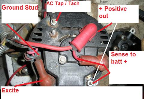
I had a question on how my old alternator is wired. It had four posts. Positive Out, Sense, Excite and AC Tap. As I understand it the post marked Excite is used to jump start or excite the alternator to charge. The positive out is just that. It was wired with a #10AWG directly to the Starter with a jumper to the sense stud. Why is that? Can someone explain what the sense and excite post's function are?

My new alternator has four Posts. Two AC Taps/Tach, a ground stud and a positive out stud. Do you think I could wire the alarm wires to an AC Tap?
 

Attachments

Sep 19, 2006
643
SCHOCK santana27' lake pleasant,az
I'd check the voltage and current at that lug first. it may not have a diode so it could be ac not dc
 
Feb 6, 1998
11,701
Canadian Sailcraft 36T Casco Bay, ME
The Blue & Pink

If I remember correctly the blue and pink wires on that alternator are for the alarm system and the ignition excite. You don't say what your new alternator is but there is a good chance it is a self excite unit that won't need an ignition on excite. I think the blue runs to the low oil pressure switch etc. and the pink is from ignition but I don't have a wiring diagram for your motor to consult..

I have re-labeled your photo (there should be a ground stud behind the blue/pink):
 

GuyT

.
May 8, 2007
406
Hunter 34 South Amboy, NJ
The sense wire is a nice feature on an alternator.
Immagine if you have a 20 ft. run of wire from the alternator to the battery.
When there is a high charge current coming out of your alternator, there will be a voltage drop in that 20 ft. of wire.
The sense wire if connected to the battery will force the alternators regulator to compensate for the voltage drop. This will lead to quicker charges.

If there is a jumper locally on the alternator between the + out and the sense, there is no compensation for the voltage drop and you will go into a float charge state earlier on a high charge.
 

Bob S

.
Sep 27, 2007
1,797
Beneteau 393 New Bedford, MA
Maine, I bought the Leece Neville that you so eloquently illustrated (thank you). Pictured is the stock alternator that I took a picture before removing it. The new one, as you know, has 2 AC Taps, a ground and positive out. Where would you suggest I wire pink and pail blue alarm wires. Are they needed with a self exited alternator?

Also, the positive out was wired to the starter which is attached to the C post on the DP switch. It also travels back through the volt meter on the cockpit instrument panel. With the new set up runing directly to the house bank, I cut and removed the section from the alternator to the starter but kept the run from the starter to the panel.
 
Feb 6, 1998
11,701
Canadian Sailcraft 36T Casco Bay, ME
You won't

Maine, I bought the Leece Neville that you so eloquently illustrated (thank you). Pictured is the stock alternator that I took a picture before removing it. The new one, as you know, has 2 AC Taps, a ground and positive out. Where would you suggest I wire pink and pail blue alarm wires. Are they needed with a self exited alternator?

Also, the positive out was wired to the starter which is attached to the C post on the DP switch. It also travels back through the volt meter on the cockpit instrument panel. With the new set up runing directly to the house bank, I cut and removed the section from the alternator to the starter but kept the run from the starter to the panel.
You won't need the self excite wire but will need to address the alarm wire using your own engines wiring diagram.

If you removed the 10ga section between the alt & starter you won't get any charging unless you run a new wire from the alt directly to the batt switch or the house bank. My alt runs directly to the back of the batt switch but is on the bank 1/house post vs. the output post.

You say "volt meter" do you mean voltage gauge or ammeter? If it is an ammeter loose it asap and replace it with a standard volt gauge. On some Catalina's, of your vintage, the entire output of the alt ran through the ammeter which was a bad idea no matter how you sliced it up.

I wish I had a wiring diagram for your particular engine but I don't know what it is? Perhaps Stu has one from the C-34 organization as the C-34's used the M-25's as well (M-25 XPB/XPA/XPBC etc.)

On the new alt I would.

Connect the tach to either of the AC Tap posts

Connect the pos output directly to the house bank or house post of the batt switch with at least 8ga wire but 6ga or larger is better.

Connect the same size wire to a clean ground on the engine and to the ground post of the alt.

Figure out how the wiring of your alarm system works and deal with it. Universal made some changes to the alarm system over the years and without a wiring diagram I can't accurately make a comment on how you'll re-arrange this.

As I said Universal made many changes over the years to the alt wiring. Here is the wiring for my 2005 M-25 XPB-C. Two wires, pos out and tach sense.
 

Bob S

.
Sep 27, 2007
1,797
Beneteau 393 New Bedford, MA
If you removed the 10ga section between the alt & starter you won't get any charging unless you run a new wire from the alt directly to the batt switch or the house bank. My alt runs directly to the back of the batt switch but is on the bank 1/house post vs. the output post.
I ran #2 directly to the battery compartment and attached it to a 150 amp fuse then to the house positive.

You say "volt meter" do you mean voltage gauge or ammeter? If it is an ammeter loose it asap and replace it with a standard volt gauge. On some Catalina's, of your vintage, the entire output of the alt ran through the ammeter which was a bad idea no matter how you sliced it up.
Meant voltage gauge.

I wish I had a wiring diagram for your particular engine but I don't know what it is? Perhaps Stu has one from the C-34 organization as the C-34's used the M-25's as well (M-25 XPB/XPA/XPBC etc.)
I got this from Kent at Catalina. I traced the wires coming out of the terminal block. They didn't match wire color going in and out. This is how it's wired on my boat.


On the new alt I would. Connect the tach to either of the AC Tap posts
Done

Connect the pos output directly to the house bank or house post of the batt switch with at least 8ga wire but 6ga or larger is better. Connect the same size wire to a clean ground on the engine and to the ground post of the alt.
fused 2awg directly to house positive and 2awg to ground.


Figure out how the wiring of your alarm system works and deal with it. Universal made some changes to the alarm system over the years and without a wiring diagram I can't accurately make a comment on how you'll re-arrange this.
That's what confused me, The light blue and pink are both alarm wires, I think. At least it's shown that way on Catalina's diagram.

I haven't tied the house batteries into the system yet but I did tie in battery 2 so I could locate the ignition wire #7 on the terminal block. (red with white stripe) I spliced into it for the external regulator. It comes on when the key is on only. Now that I think about it the key alarm was chirping without either wire attached.
 
Feb 26, 2004
22,984
Catalina 34 224 Maple Bay, BC, Canada
I have been

working with Bob offline on his system, in great detail and he's done a fine job so far. The reason he asked this question was I didn't know what the wires he showed me at the back of the LN alternator were, and I suggested to him that he ask Maine Sail since I remembered MS had done quite a bit of work with the LN alternators.

Bob's run his alternator output to the house bank and has all of that figured out just fine, it's no longer an issue, and he's avoided the battery switch with his alternator output. The old wire between the starter and the alternator is also no longer an issue, he's got that covered, too. Let's not complicate things any more than need be.

What his basic question is: What are the wires at the back of the LN alternator and where do I connect them?

Since he doesn't have a "plug and play" alternator to simply plug the wiring harness from his new regulator into the alternator, he needs to know the answers, and I was confused by the two positive outputs of the LN alternator.

I sent Bob my sketches from my alternator regulator upgrade (see: http://c34.org/bbs/index.php/topic,4548.0.html) and he's simply trying to do the same job for his boat as I sketched for mine.

One's gotta be the ignition wire, and one's gotta be the tach, and the wiring harness usually has the field wire going back to the regulator.

All his question is, is which is which from the LN alternator?
 
Feb 26, 2004
22,984
Catalina 34 224 Maple Bay, BC, Canada
In addition

Bob, you may want to simply send MS your system wiring diagram to avoid a lot of going back over what you and I have already discussed. I know MS will understand completely once he sees what your system wiring diagram shows, or just post it here.
 

Bob S

.
Sep 27, 2007
1,797
Beneteau 393 New Bedford, MA
The only question is where do i attach the pink and light blue wires that were attached to the excite post of the old alt. All my re-wiring is done. I traced these 2 wires back to the cockpit behind the instrument panel by color. The light blue is the oil pressure sender. The pink must be the ignition power alarm? At least that is my understanding. One of them was used to excite the old alternator. I'll assume the pink one which isn't needed anymore. I can cut and tape it. I want the oil pressure alarm to work, where would I connect it to the new alternator?

[FONT=&quot]Picture compliments of MaineSail
[/FONT]
 

Attachments

Feb 26, 2004
22,984
Catalina 34 224 Maple Bay, BC, Canada
Oil Pressure Alarm Wiring

TI want the oil pressure alarm to work, where would I connect it to the new alternator?[FONT=&quot]
[/FONT]
Bob, not sure why the oil pressure alarm wire would get connected to an alternator. The wire is simply part of the harness and should come off the engine's oil pressure sensor. It has nothing to do with the alternator wiring.
 
Feb 6, 1998
11,701
Canadian Sailcraft 36T Casco Bay, ME
Bob & Stu

Bob, not sure why the oil pressure alarm wire would get connected to an alternator. The wire is simply part of the harness and should come off the engine's oil pressure sensor. It has nothing to do with the alternator wiring.
I have not had a chance to check back in but my guess is this.

The pink wire is probably energized by 12v when the key is on exciting the alts regulator. Of course it could be the blue wire too. This could be confirmed with a DVM by connecting the red lead of the DVM to the pink wire and the black to gnd and turning the key on then doing the same with the blue wire

I would then guess the pink wire fed the blue wire, that leads to the oil switch, its 12v signal. Seeing as the excite is not needed on the new alt and the blue and pink were connected together anyway, at that post, I would think connecting the blue & pink together but not to the alt is a safe bet..

When I get a few seconds, and I'm not on my crackberry, I will try and look at that wiring diagram.

Hope that made sense and please know that this is just an educated guess based on the photos and some past knowledge of Universal diesel wiring..
 
Oct 23, 2008
138
Macgregor v22 Tacoma
I would agree with Maine Sail the pink wire is likely getting energized from the excite post.
 

Bob S

.
Sep 27, 2007
1,797
Beneteau 393 New Bedford, MA
Thanks everyone! I have to admit I'm electrically challenged but thanks to this site I've been able to accomplish a lot this winter. A special thanks to Stu for all his guidance through a sea of wires and Maine for his fantastic pictorial guides.:dance:
 
Feb 26, 2004
22,984
Catalina 34 224 Maple Bay, BC, Canada
Bob, it was my pleasure. And...you are NO LONGER electrically challenged! :):):)
 
Status
Not open for further replies.