
My Epoch 460ah LiFePO4 Upgrade Plan

Jul 28, 2024
73
Catalina 310 238 Berkeley, CA
I’m considering upgrading to the Epoch 460ah LiFePO4 battery for my house bank.

In order to simplify things and minimize costs with charger and alternator upgrades, I would leave one of my 200ah AGM batteries in place to act as the starting battery, an emergency reserve for house loads, and the primary charging point for my alternator and shore power charger. I would then utilize the Orion XS DC-DC charger to slowly cross-charge the LiFePO4 battery. I plan for 460ah to provide enough power for my longest cruises (~6 days, offset by solar), so I’m not worried about high-speed charging from the alternator nor shore power.

I’ve been carefully reviewing the various recommendations, ABYC requirements, etc.

The diagram below shows my proposed install, which at the moment has the virtue of only requiring the battery, an Orion XS, and changing from a 1-2-Both main disconnect to a dual-circuit on-off switch.

Curious to hear some feedback. I’ve been seeing Maine Sail posting recently (Hi!), so excited to see if he jumps in with his expensive wisdom on the topic

Note that for monitoring, my existing Victron Smart Shunt would see only the AGM battery current, as I would use the Victron CAN monitoring of the in the Epoch battery via NEMA2000 converter for monitoring it. That way I would monitor each bank independently via NMEA2000.

Thanks,

Max
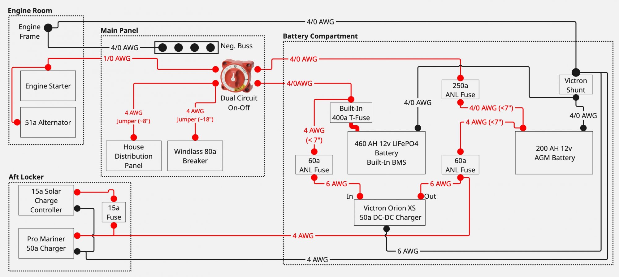
LiFePO4_Plan_V001.jpg
 

Attachments

jssailem

SBO Weather and Forecasting Forum Jim & John
Oct 22, 2014
24,565
CAL 35 Cruiser #21 moored EVERETT WA
I’ve been seeing Maine Sail posting recently (Hi!), so excited to see if he jumps in with his expensive wisdom on the topic
Yes. It is great to see. It is why I bought him a cup of coffee and encouraged others to do the same. Would hate to see him put his site behind a pay-as-you-go firewall.
 

jssailem

SBO Weather and Forecasting Forum Jim & John
Oct 22, 2014
24,565
CAL 35 Cruiser #21 moored EVERETT WA
I did not see any glaring errors. Nice work.
I am not an expert Marine Electrician, so I might have someone validate it. Been reading Insurance documents recently, and that industry is catching onto the installs of LiFePO4 batteries. They love DIY installs as they readily deny claims based on the assumption that a DIY install is not to ABYC standard. You are guilty and need to prove you are innocent, in their eyes. Document everything that supports your care and competency to make the improvement you have made.
 
Jul 28, 2024
73
Catalina 310 238 Berkeley, CA
Updated version with a couple corrections: I had the in/out labels reversed on my Orion, and one of the grounds on the wrong side of the Smart Shunt.

Updated v002:
LiFePO4_Plan_V002.jpg
 

Attachments

Jul 28, 2024
73
Catalina 310 238 Berkeley, CA
am not an expert Marine Electrician, so I might have someone validate it. Been reading Insurance documents recently, and that industry is catching onto the installs of LiFePO4 batteries. They love DIY installs as they readily deny claims based on the assumption that a DIY install is not to ABYC standard. You are guilty and need to prove you are innocent, in their eyes. Document everything that supports your care and competency to make the improvement you have made.
Indeed. My insurance company has told me a professional installer is required. At this point I'm just in the planning phase as a look for the right installer to work with. Depending on the installer cost, I may just settle for my current 2x 200ah AGM config with a bigger alternator and additional solar. I'd love the weight savings and elegancy of a LiFePO4 system.
 
May 17, 2004
6,154
Beneteau Oceanis 37 Havre de Grace
For the solar controller, you might want more than a 15 amp fuse to avoid nuisance trips since it’s a 15 amp controller.

If you’re staying with the 51(?) amp alternator you’ll probably need to dial the DC-DC down to about 25 amps to not overwhelm the alt. I’m not sure if there’s a good way to dial it down when charging from the alternator but back up when on the shore charger.
 
Jul 28, 2024
73
Catalina 310 238 Berkeley, CA
If you’re staying with the 51(?) amp alternator you’ll probably need to dial the DC-DC down to about 25 amps to not overwhelm the alt. I’m not sure if there’s a good way to dial it down when charging from the alternator but back up when on the shore charger.
Good call-out. I may have already upgraded to a 100a Balmar with external regulator by the time the LiFePO4 project happens. If not, turning the Orion down to 25a should work. I could always turn it up in the app if I happened to need to get a fast overnight charge from a depleted hosue bank, but I think that's unlikely.
 
Jan 11, 2014
14,018
Sabre 362 113 Fair Haven, NY
There are some fusing and wire size issues.

The wires leading to the House panel and windlass are either way undersized, they need to b 4/0 or there needs to be a fuse earlier in the circuit that is much smaller than the 400a Class T in the battery itself.

Like wise, the 4 AWG cables from the battery are unprotected, they need fuses or the wire needs to be bigger.

With a better fusing plan, you won't need all that 4/0 cable. The battery's max continuous draw is only 250a. Most of our small diesels only draw ~250 for a few seconds, which the Epoch can handle and is will within the ampacity of 2/0 cable. So from the battery run 2/0 to a 300a fuse to a bus. Blue Sea makes a bus that uses MRBFs. All of the loads and charging sources are then tied to that bus with appropriately sized fuses.

There should be switches at each battery so the battery can be completely isolated. There are 2 schools of thought, ABYC suggests the switch should come after the main fuse, 46 CFR (the CG rules for commercial vessels) says switch first so the fuse can be serviced with no current to the fuse holder.

Epoch claims the internal Class T fuse makes the battery ABYC compliant, however, that is only half the story. In order to be ABYC compliant all of the cabling downstream of that 400a fuse must be rated to handle 400a. Practically that is crazy. The cost, weight, and handling of cable that large is simply unnecessary for the loads we have on our boats. On my boat, I run less than 50a on the house panel, the windlass only has a couple of hundred amp inrush current, after which it takes less 100a. Those loads can be handled by much smaller cable than 4/0.
 
Jul 28, 2024
73
Catalina 310 238 Berkeley, CA
Thanks for the thoughts Dave!

This plan is using cabling that's already in the boat (most of this system is existing, less the Epoch and DC-DC). I certainly would not have bought all that 4/0 o_O.

The wires leading to the House panel and windlass are either way undersized, they need to b 4/0 or there needs to be a fuse earlier in the circuit that is much smaller than the 400a Class T in the battery itself.
I was also thinking about those jumpers after the main switch to the panel and windless. The boat came from the factory with 4/0 feeding the switch, and then those #4 jumpers to the panel and windlass breaker. I suppose terminal fuses could be added to protect them. While fuses would be ideal, I wonder if this is covered by the "40 inch rule" so long as the jumpers were sheathed?


Like wise, the 4 AWG cables from the battery are unprotected, they need fuses or the wire needs to be bigger.
The 4 AWG cables from each battery are feeding 60a ANL fuses. They are drawn as less than 7". Are you saying they need to be larger, even if less than 7"? If so, what's the standard for how large?


Epoch claims the internal Class T fuse makes the battery ABYC compliant, however, that is only half the story. In order to be ABYC compliant all of the cabling downstream of that 400a fuse must be rated to handle 400a. Practically that is crazy. The cost, weight, and handling of cable that large is simply unnecessary for the loads we have on our boats. On my boat, I run less than 50a on the house panel, the windlass only has a couple of hundred amp inrush current, after which it takes less 100a. Those loads can be handled by much smaller cable than 4/0.
I agree that fuse seems way too big. I would replaced with a smaller Class T if possible, so long as it still has the AIC needed. Speaking of which, I wonder if Epoch is publishing short current rating for the battery. If not, using the new ABYC 11.10.1.3.2.2 provision would require 23k amps of AIC for that battery!

So from the battery run 2/0 to a 300a fuse to a bus. Blue Sea makes a bus that uses MRBFs. All of the loads and charging sources are then tied to that bus with appropriately sized fuses.
I agree that would be a much cleaner approach. My plan was attempting to reuse as much of the cabling and fuse blocks already mounted in the boat as possible. I'll think about a more centralized fusing approach as you describe.
 
Jul 28, 2024
73
Catalina 310 238 Berkeley, CA
. If not, using the new ABYC 11.10.1.3.2.2 provision would require 23k amps of AIC for that battery!
Scratch that. I see now that there's a 11.10.1.3.2.3 that caps the requirement at 20ka of AIC.
 
Last edited:
Jul 28, 2024
73
Catalina 310 238 Berkeley, CA
Here's a version that provides better fusing utilizing MRFB fuses, but still avoids new cable runs.

LiFePO4_Plan_V003.jpg
 
Jul 28, 2024
73
Catalina 310 238 Berkeley, CA
There's still the question of individual battery disconnects as opposed to the dual circuit one. Individuals would be nice, just more holes/mounting etc.
 
Jan 11, 2014
14,018
Sabre 362 113 Fair Haven, NY
Here's a version that provides better fusing utilizing MRFB fuses, but still avoids new cable runs.

View attachment 237336
Sometimes simpler is better. I'm surprised Catalina used 4/0 cable, that's a huge expense for a production boat. I assume your swapping the built-in 400a fuse with at 200a. You might consider upping that to 300a if you plan to use the house battery as a back up to the start/reserve battery. If so, read on.

There's still the question of individual battery disconnects as opposed to the dual circuit one. Individuals would be nice, just more holes/mounting etc.
The Dual Circuit switch comes in 2 flavors, one in which the 2 circuits can be combined and one where they can't. The combine version (DC+) is an easy way to have all systems run off either battery bank, the house serves as a reserve start battery, the start serves as a reserve house battery. To do this properly it is necessary to have each bank controlled by a simple On/Off switch. In a mixed chemistry system, it is important to isolate the batteries and if one battery fails it needs to be isolated. The one caveat is the LA and LFP batteries should not be placed in parallel because of the different voltages between the batteries. And of course there is an exception, some AGM batteries have voltages and charge parameters that are the same as LFP.

Yesterday, Will Prowse released a review of the Epoch V2-T battery. If you have the newest version of this battery the video should help allay any buyer's remorse you might be feeling.


jssailem

SBO Weather and Forecasting Forum Jim & John
Oct 22, 2014
24,565
CAL 35 Cruiser #21 moored EVERETT WA
Two queries
  1. Why the MRBF fuses on the distribution side of the main switch. The switch is not a stored power source (i.e. battery)
  2. Alternator is wired directly to a battery not the main switch. In your plan that was the AGM Start Battery. There can be a safety switch at the alternator to cut the lead to the battery while the alternator is being worked on. No fuse needed on this safety switch. Fuse is on the battery.
 
Nov 21, 2012
807
Momentarily Boatless Port Ludlow, WA
What's the total distance between the starter and the start battery? You have so many additional points of resistance between them that your voltage drop will be significant. The 200A fuse is barely adequate. I think you will have nuisance blows on a 1/0 cable.

If I ran the zoo, I'd ditch the 200A AGM for a small group 24 start battery charged by an 18A DC-DC charger, go with a bigger alternator and charge the Epoch from the alternator. You can still power emergency loads off the Group 24.

However, depending on the make and model of your windlass, you might need to run it off AGM. Some of them don't like LFP. Your diagram doesn't show how it will be powered.
Two queries
  1. Why the MRBF fuses on the distribution side of the main switch. The switch is not a stored power source (i.e. battery)
  2. Alternator is wired directly to a battery not the main switch. In your plan that was the AGM Start Battery. There can be a safety switch at the alternator to cut the lead to the battery while the alternator is being worked on. No fuse needed on this safety switch. Fuse is on the battery.
1. A change in cable size (from 4/0 to 4 AWG) requires fusing to protect the smaller cable.
2. I need to put some thought into this, but the alternator-starter-switch path to the battery bugs me. There are 8 connections between the alternator and the battery. Focus on simplifying that path. The only reason to connect the alternator through the starter post is to save money on cable. Wire it directly to the battery. If the cable is adequately sized, no fuse is needed, as the output is self-limiting.
 
Jan 11, 2014
14,018
Sabre 362 113 Fair Haven, NY
2. I need to put some thought into this, but the alternator-starter-switch path to the battery bugs me. There are 8 connections between the alternator and the battery. Focus on simplifying that path. The only reason to connect the alternator through the starter post is to save money on cable. Wire it directly to the battery. If the cable is adequately sized, no fuse is needed, as the output is self-limiting.
Most engines come with the alternator wired to the starter because it reduces wiring cost and installation cost for the boat builder, only one wire to connect instead of two.

The switch John is talking about is usually referred to as a Service Disconnect and it is installed near the alternator. Turning this off allows the rest of the electrical system to function while the alternator is being serviced, otherwise the electrical system has to be disconnected at the battery DC-. It is also useful when trying frustrate a boat owner who replaced his alternator and forgot to turn the switch back on.
 
Jul 28, 2024
73
Catalina 310 238 Berkeley, CA
If I ran the zoo
I forgot how much I like this phrase :).

It's easy to want to just re-wire the whole boat and use all of the modern preferred practices: Centralized distribution buss, individual battery disconnects, alternator home run, etc. etc. As much as I'd enjoy that project, I never fail to be amazed how much the prices of wire, terminals, heat shrink, fuse holders, etc, quickly add up. I could easily spend 2x the battery cost on a re-wire, and this isn't the boat for that.

My goal with this design was to be 1) safe, 2) fully ABYC compliant, 3) reused as much wiring, panel switch mounting locations, etc. as possible, 4) avoid going down the path of an alternator upgrade and leave the stock one alone, since I'm not doing multi-week cruising. Once I slide all the way down the slippery slope with lots of new switching, wiring, monitoring, alternator, etc., I can no longer justify the cost and just end up sticking with my dual-AGM setup.

The above design adds a handful of MRFB fuses, changes the 1-2-BOTH switch for the dual circuit or dual circuit + switch, but otherwise uses the wires that are already in the boat.

I'll noodle on the feedback and think about more minimally invasive ways to fold in the proposed changes.

Another, completely different, direction that may become more of an option as more batteries are released is a simpler dual 300-ah LiFePO4 setup with an alternator regulator upgrade that can handle charing LiFePO4 directly. The relativity tiny cranking requirements of my M25XPB could make this possible. That removes the DC-DC charger from the mix and starts to look a lot more like the original dual-battery design as the boat was originally wired. Maybe I'll draw that one up next.

I'm surprised Catalina used 4/0 cable,
I might have misremembered this as I'm away from the boat for a few more weeks. I might be 2/0, but it's definitely bigger than 1/0.
If I ran the zoo, I'd ditch the 200A AGM for a small group 24 start battery charged by an 18A DC-DC charger, go with a bigger alternator and charge the Epoch from the alternator. You can still power emergency loads off the Group 24.
This is another option as well, and save some weight to help with my slight list to port. But, as noted above, why not just go all the way now that some of these LFP's can happily make 400a cranking power for short durations?

The only reason to connect the alternator through the starter post is to save money on cable. Wire it directly to the battery. If the cable is adequately sized, no fuse is needed, as the output is self-limiting.
I know ABYC has fusing exceptions for alternators, but I don't like the idea of an unfused wire running throughout the boat. I'd still want fusing to protect the conductor.
 
  • Like
Likes: jssailem
Jan 11, 2014
14,018
Sabre 362 113 Fair Haven, NY
The only reason to connect the alternator through the starter post is to save money on cable. Wire it directly to the battery. If the cable is adequately sized, no fuse is needed, as the output is self-limiting.
I know ABYC has fusing exceptions for alternators, but I don't like the idea of an unfused wire running throughout the boat. I'd still want fusing to protect the conductor.
The normal rule is to fuse at the source of power because it protects the wire down stream. For current limited devices, battery chargers, solar controllers, and alternators the rule is fuse close to the battery. Wire can be sized to accommodate the max current of the device, but it can't be sized to accommodate the max current from the battery if the short is at the current limited device.

For example. if while working on the alternator a wrench connects the B+ with the engine block there will be a big bang and spark if there is no fuse at the battery end of the alternator cable. With a fuse there, the bang will smaller as the fuse blows.
 
Jul 28, 2024
73
Catalina 310 238 Berkeley, CA
So here's another idea:

Dual Epoch 300ah "dual purpose" LiFePO4 batteries that support up 300a continuous current and 1000a for cranking. I've read elsewhere that M25xpb starter uses around 225amps.

The alternator would have to be upgraded to an externally-regulated one that has the temperature management to charge LiFePO4 batteries.

Once again I've drawn it in a way that utilizes the existing wiring in the boat (though now I'm thinking those main battery cables are 2/0 not 4/0).

The switching is the old-school 1-2-Both style just like the boat came from the factory with. It would be used just the same as I do today with the AGMs: Run 'BOTH' most of the time, switch loads over to a single battery when power budgeting and wanting to preserve one as reserve for cranking. As other has commented, it should be possible to fully isolate one of the batteries in the case of a failure. I think this provides that, since in the case of a failure the 1-2-Both switch would just be set to the opposite battery.

The Pro Mariner could be put in LiFePO4 mode and charge both batteries as it does today.

No more DC-DC charger needed.

I've added one of those handy dual-fuse MRFB holders to the output of the 1-2-Both switch, to fuse the engine feed and the main panel. For the 4awg feed to the Windlass breaker, which is only about 18" away, I would lean on the 40" ABYC provision by sheathing the cable.

Still just an idea, but let's keep the thinking going.

LiFePO4_Plan_V101.jpg


Still an expensive system: $3k for batteries, $1k for alternator, probably $500 in fuses / jumpers.
 
Last edited:
Jan 11, 2014
14,018
Sabre 362 113 Fair Haven, NY
A cleaner simpler system, a great improvement.

The 2/0 cables are more reasonable than the 4/0.

If you go with the Balmar 100a and the 618 regulator, be sure to get the Blue Tooth module too. Programming the 618 with the magnetic reed switches is an exercise in frustration, the BT module is worth every penny.