Lately there has been a lot of discussion around external vs. internal voltage regulation so I wanted to pass this info along. I had sent this to another member in an off line conversation a few weeks ago but tweaked it a little for a general posting.
If you want to avoid the diatribe below: In almost all cases an external regulator will yield a better performing charging system, but it may not make "financial sense" for your particular use.
The choice of external vs. internal should ideally be based on:
I am making a LOT of general assumptions below so be patient:
1- Voltage is the pressure that cause the batteries to accept current.
2 - Amps are the "flow" and the higher the pressure/volts the more the flow/current can be.
3 - The alternator is not "forcing" or dictating amps to a battery, it does not do this, the battery "accepts" or lets current flow, based on voltage at the battery terminals and SoC.
4 -The alternator provides the current up to what it can provide or the battery can accept at XX.XX volts. Prior to the battery reaching the absorption voltage the alternator is basically *full throttle providing all the current it possibly can.
*Unless the regulator uses a temp gradient type regulator.
5 - A voltage regulator is little more than a VOLTAGE LIMITER. All it really does is LIMIT or maintain a preset voltage once the battery bank gets to the target voltage. External high performance regulators can limit voltage based on battery temp, alternator temp, time at voltage & other parameters but they still limit voltage.
Temperature compensation of the alternator and batteries is one of the most useful features of external smart regulators. Voltage limiting or voltage regulation modifies the alternators field voltage/current to maintain the desired set point voltage. This regulation technique is called pulse width modulation. Simply put the on time and off times are modulated at insane speeds in order to maintain the desired voltage set point the regulator wants to see or is limiting voltage to.
If the voltage starts to creep up the PWM or off time to the alternator field gets extended. Cutting back the alternators field via PWM, limits the current the alternator can produce and thus a voltage limit is maintained and voltage over-shoot is prevented. Good quality external regulators can control voltage to within a 10mV to 30mV range or 0.01V to 0.03V.
If you add a big load the regulator will boost the fields on time to maintain the voltage set point. PWM all happens so fast that you need an Oscilloscope to even begin to see it. If the load exceeds what the alternator can produce, eg: a bow thruster, the regulator reverts to full field or 100% output. Voltage limiting and PWMing of the field go hand in hand.
6 - A typical voltage regulator has no clue what the amperage is coming our of the alternator. All the regulator knows is voltage, hence the term voltage regulator. Voltage regulators regulate based on voltage not amperage. While the amperage out of the alternator changes up & down to maintain a voltage set point the regulator is doing all of this all based on voltage.
7 - The internal resistance of a battery (SoC) determines the current it "accepts" or takes from the alternator to maintain a voltage at a specific state of charge.
With a small alternator, in bulk mode, the alternator will be limited to what it can physically produce, while hot. What it can produce is based on RPM and alternator winding temperature. Bulk just means "full field" or that the alternator voltage sense circuits has still not attained the pre-set voltage limit of the regulator. This stage of charging is called BULK or constant current (CC). In Europe, under DIN standards, they often call bulk charge a BOOST.
The relation ship of alternator current to banks size also plays a role. A small alternator attains the CV stage voltage limit at a higher SOC. Conversely, if you have a very large amperage alternator, the bulk period will be shorter and the battery bank will attain the voltage limit (CV stage) at a lower overall SOC. With a large source of current a battery can come up to absorption voltage more quickly because the battery can not accept the current, into the battery plates, as fast as the source can provide it. This builds a surface charge on the plates and results in driving the voltage up faster than a smaller current source.
8 - Let's address charging lingo such as *Bulk, *Absorption & Float.
FACT: Both smart and dumb regulators do both bulk (CC) and absorption (CV) or CC/constant current & CV/constant voltage stages.
BULK / CC - Bulk charging is essentially applying the max field the alternator rotor in both smart and dumb regulators. Bulk charging is any period of time before the regulator has attained it's absorption voltage limit at the battery terminal, or alternator, if "voltage sensed" there. In the bulk stage the alternator is delivering the maximum current it that it can based on copper temperature and rotor RPM. How much is needed to drive each alternator depends upon the specific alternator. Many alternators can pump out 100% of their rating with a field voltage of less than half that of the battery bank voltage, while others require 8-9V and massive 350A+ alternators may require upwards of 10-11V.
As a battery charges during bulk its terminal voltage gradually rises. If the regulator, smart or dumb, has been set to 14.4v then until the batteries hit 14.4v is considered bulk charging. Bulk charging is also called constant current charging meaning the charge source, in this case an alternator, is supplying all the current that it physically can at its current temperature and RPM.. Bulk is where the maximum current will flow into the battery because the batteries internal resistance is low due to being discharged.
During bulk charging the differential in pressure or voltage is at its greatest and thus the battery is accepting all the current the alternator can feed it as the terminal voltage slowly rises.
ABSORPTION / CV - Once the battery attains the voltage limit the regulator switches from the bulk/constant current stage to the absorption/constant voltage stage and begins regulating to the voltage limit.
Once the voltage is held steady or becomes voltage limited the current being accepted by the battery begins to decrease. This is because the regulator is now operating in CV or constant voltage mode and as SOC rises the battery needs or accepts less and less current in order to maintain & not over shoot the voltage limit.
FLOAT/CV - Float voltage is a further reduced constant voltage limit applied by a smart regulator. Dumb regulators do not do a true float. If you feel you need float, because you motor a lot more than you sail, you's want a smart external regulator.
All of the above is based on what I have seen, read or heard most people misconstrue. You may not have misconstrued any of it but it is good to get out there.
Marketing Mumbo Jumbo: Just because companies such as Balmar call "bulk" (BV) a voltage limited stage of charging, the simple answer is that this is not true. Charge product manufacturers that do this, and we are a large Balmar dealer, are simply using incorrect terminology. Some companies do this purposely to confuse & confound the customer into thinking they are getting more. In teh case of Balmar the EE who designed the regulator used three CV stages and one CC stage. He called the first CV stage BV or Bulk Voltage, the second stage AV or Absorption Voltage and the third FV or Float Voltage. Seeing as Balmar was the first to have two absorption level voltages this seemed to make sense.
Of course, this is really all just marketing and we live with it every day. Bulk charging is constant current or when related to an alternator constant potential based on heat and rotor RPM. Bulk is simply not a constant voltage stage. In recent years more and more companies have begun using the incorrect terminology of "bulk voltage". You can have a bulk transition voltage, the point at which it transitions to absorption, but you can't really have bulk voltage that is constant voltage.
During bulk charging the battery voltage is ALWAYS on the RISE thus it can not be a "bulk constant voltage".. More appropriate terminology, as related to products such as the Balmar regulators might be Absorption 1 & Absorption 2.
As mentioned above I know why Michael, the designer of the Balmar regulators, named it bulk voltage. I had long conversations with Michael, including discussions specifically about terminology, and he admitted it was an incorrect use of terminology that just got adopted by the marketing department. Of course, at the time, with a regulator that had 15,000 lines of code, correct industry accepted and defined terminology was far from the first thing on his mind.
At the bulk to absorption transition voltage the regulator begins PWMing the field wire in order to maintain the pre-set voltage limit. With an adequately sized alternator this is often stated & repeated as a state of charge (SOC) of somewhere around 80% SOC. This however is not always a truism.
The SOC at which you attain absorption voltage is entirely dependent upon how much charging current you have. With a small solar array, you may not hit absorption voltage until 96% SOC and with a massive alternator you may hit absorption at 65% SOC. The point at which your battery bank attains the voltage limit is entirely depending upon how much current you have available. On top of current availability sulfation, battery state of health and *incorrect voltage sensing, among others, will change the point at which the battery attains the CV/voltage limit.
*Accurate voltage sensing is critically important on sailboats that desire short engine run times. Factory alternators do a horrible job with this. For more in-depth discussion on this subject see: Alternators and Voltage Sensing Why It's Important
Sulfation & SOH Impact Bulk Charge Time:
A sulfated battery or a battery in poor state of health (SOH)will quickly rise to absorption voltage despite not yet actually being charged. Simply put until a battery reaches the voltage limiting set point, absorption charging, all regulators, smart or dumb, simply "*full field" the alternator to what ever the regulator can produce in field voltage/ field current. Battery chargers and solar controllers operate the same way.
If your battery bank starts out at 50% SOC and you;re attaining the voltage limit in a short period of time the battery is likely shot. At a charge rate of .2C, or 20% of Ah capacity in charge current, it should take an hour or more to attain the absorption voltage limit.
*The exception is an alternator with a thermistor/temp gradient regulator.
Can Internal "Dumb" Regulators Really Do Bulk Charging?
Yes they absolutely can, though there are certain things that can impact just how well they do this compared to an external regulator.
The question below was posed on an external alternator regulator manufacturers web site. This company builds smart external regulators and alternators.
Question:
As I understand it most of the regulators regulate voltage not amperage? Before the regulator hits the absorption set point, mine is 14.4 volts, they are simply full fielding the alternator. So do both dumb and smart regulators do the same to the alternator, apply full field until the absorption voltage is reached?
Answer from Manufacturer:
You're correct, during the bulk phase, the alternator is 'full fielded', by all regulators. But the term 'full fielded' is loosely defined as applying the maximum voltage that can be applied by the regulator. If you measure the voltage drop between B+ and field during the bulk cycle you'll find that an XXXXX Regulator drops the least voltage of any regulator. More voltage on the field means more Amps.
While the external regulator can produce a higher field potential, is this always necessary? The answer is no, it is not always necessary. We should consider that an external regulator must be able to drive any alternator it is fitted to, and it will need the capability to deliver a wider range of field potential to any alternator out there. External regulators can deliver upwards of 15A to drive the field. An internal "dumb regulator" only needs to produce enough field potential to drive the specific alternator it was designed to be fitted on in order to attain its maximum output rating. For some alternators this may require as little as 4A. There is no reason for Delco, Bosch, Paris Rhone, Leece-Neville etc. to design an internal regulator capable of 15A when the alternator is only needing 4A to attain its full output. In industry pennies count. A general fit external regulator must be able to drive any alternator so they are built to do this. While the statement above is technically true it is misleading at best.
A few years ago I spent an entire Saturday at a friends shop conducting experiments with many different internal dumb regulated alternators. This shop has a $30,000.00 alternator testing machine I got to play with for hours.. I loaded random internally regulated alternators into the machine and tested them for max alternator rated output.
Bottom Line? Every single internal dumb regulator applied enough field voltage/current to achieve the max rated output of the alternator, every one. Keep in mind however this was "cold testing" and as some alternators heat up they reduce the voltage limit based on internal thermistors. I will get to this later.
While you may be able to apply more field potential, as most external regulators have the ability to, you can't exceed the alternators physical capabilities. If the alternator can hit its maximum output rating with a *dumb regulator, then a smart one, set to the same voltage and sensed at the same spot, will not increase charging times in bulk stage.
*Excludes thermistor equipped/temp gradient internal regulators
This video may help pull some of the above together:
Let's Put This Into Practice:
*If you take two identical 100 amp alternators and two identically discharged battery banks and one smart and one dumb regulator (truly dumb, no thermistor), and they both sense voltage at the same point in the system, they will both charge at the same speed in bulk. No magic here just basic Ohm's law stuff. Full field is full field.
*Assumes everything is the same except the regulators.
The bottom line truth is an *external regulator will not charge faster if the voltages are set equal and the set up and wiring is the same. (*non-thermistor type)
External Regulation Instillation Practices Matter:
The sad reality is that the vast majority of external regulators I see installed are almost always set up to physically charge slower than they can. Due to improper programming and incorrect installation practices they enter float far to early in the charge curve. This robs owners of the charging performance they paid for. The "advanced programming" menu is Balmar regulators is there for a reason! The temps sensors are sold for a reason!
External regulators WILL DEFINITELY charge faster if you set them up correctly using the correct absorption voltage for your batteries. You push absorption voltage higher with an external regulator because you have a float feature after a high absorption voltage. You would not want a high absorption voltage setting, actually the only CV setting, on a "dumb" regulator.
When you dumb it down there is nothing fancy about voltage regulation/voltage limiting or PWM control of the alternators field. Smart regulators do not charge faster, when set at the same voltage set point, and all other things being equal because a battery is only going to accept what it can accept at a specific voltage and SOC.
The battery really has no clue it is hooked up to a $400.00 external regulator or a $15.00 internal regulator, all is knows is the voltage at its terminals and how much current it will accept at that SOC and at that voltage. Course if your internal regualtor is set for 14.6V and you motor down the ICW for 10 hours per day you're going to be adding water to the batteries quite often. If you do this with AGM or GEL the batteries will be getting over charged.
External regulators can be set up to charge faster and to maximize the alternators output. This only works if you set them up properly for your battery type. Sadly many installers or DIY's don't set them up this way. I would estimate that a solid 80% of the external regulators I see are still on the UFP (universal factory program) setting.. This gains you little to no benefit over a *dumb regulator in charging speed.. (*truly dumb no thermistor)
Why Do Internal Regulators Get Such a Bad Rap:
#1 Voltage sensing - Most internal internal regulators sense voltage at the back of the alternator, not at the battery terminals. The factory wiring between the batteries and alternator can induce substantial voltage drops causing the batteries to charge slow and hit limiting voltage far earlier than they should.
#2 Internal Regulator Temp Gradients - Some dumb regulators are what I often refer to as "Super Dumb". By this I mean the alternator protects itself by reducing the regulation voltage as it heats up. This serves to protect the alternator, smart for the alternator, but super dumb for deep cycle batteries. There are better ways to keep the alternator from running too hot than a thermistor protected regulator.
For a more in-depth look at this subject see here: Automotive Alternators vs. Deep Cycle Batteries
#3 Low Voltage Fixed Limit Point - Some alternators have an absorption voltage set point that is far too low, below 14.4V. Combine this with inaccurate voltage sensing & a temp gradient and you have really, really $hitty charging performance.
Are All "Dumb Regulators" The Same?
No, they are not.
Dumb:
A simple dumb regulator has but one voltage set point and that is it. It can do Bulk/Constant Current or *Constant Potential (*accounts for heat and RPM) and Absorption/Constant Voltage. If this set point is 14.4V you 're going to do okay if you're a weekend sailor with a small bank who ties to dock charging during the week. This also assumes you have minimal voltage drop between the alternator and batteries. If you move to a large bank that spends a long time in bulk these alternators can and do literally burn themselves up. I replace or rebuild approximately 5-15 alternators each year that have physically burned up from spending too much time in bulk and being chronically over-worked.
Super Dumb:
Hitachi/Yanmar, Valeo, Mitsubishi, Bosch & most newer auto-based alternators are dumber than a pound of beetle-crap to install on a boat with a deep-cycling battery bank. To the alternator or car batteries they are pretty smart but to your deep cycle batteries, and the negative impact in relation to actually charging them in a healthy manner, they are flat out stupid.
Why? Hitachi & many other automotive alternators with internal regulators, limit voltage but they also reduce voltage based on alternator temperature. They usually accomplish this using internal thermistors in the voltage regulation circuitry. In a deep cycle application this amounts to a self protective feature to try and prevent the alternator from cooking itself. In automobiles this type of circuitry is a cheap way to minimize the over charging a car battery in a hot engine compartment. Due to often super high automobile engine bay temps this thermistor reduces output voltage to a safer level. On a boat however, the batteries are not in the engine bay, or should not be, so the thermistors heat sensitivity is driven by how hard the alternator is working and the heat generated by the alternator itself from being worked hard in bulk. Remember voltage is the pressure so by reducing the limit voltage, we also reduce the current that can flow into the batteries and chop charging performance dramatically.
On boats battery temp sensing should be done directly at the battery, not inside the alternator. If you want to protect the alternator then reducing the field, not the regulated output voltage, is the proper method with a deep cycling bank. If we reduce the voltage limit, then we also reduce the current the alternator is supplying to the battery. Add in some voltage drop and we now have an 80A alternator only capable of as low as 20-30A in bulk..... The thermistor protection is good for the alternator, and it usually gets the manufacturer through the warranty period, but it is horrible for your deep cycle batteries.
The battery simply will not accept the same current at 13.4V that it did at 14.4V. As a result the alternator will run cooler but the battery will charge at a snails pace. What do you suppose this chronic under charging does to your batteries over time.......?
The behavior is that when cold you will get 14.3V to 14.4V out of the "super dumb" regulator but as the alternator heats up the "super-dumb" regulator begins to reduce the CV/voltage limit based on the alternators internal temperature. It is not uncommon to find a Hitachi alternator at 13.4V when hot. This is really, really, really bad for your deep cycle batteries.
If you have a super dumb regulator, and notice the voltage dropping, or not climbing and current output abysmal,it is likely a thermistor protected dumb regulator.
Super Dumb Rx = Get rid of it or plan to buy new batteries more often. If you have a temp compensated automotive type alternator you are really in dire need of external regulation if deep cycling a larger battery bank. I do not recommend converting these stock alternators, below 80A, to external regulation because the amount of current limiting required to get them to run at a safe temp makes them nearly useless in terms of charging current.
"So if I have a basic dumb regulator at 14.4V, with no thermistor gradient, it can charge at the same speed as an external regulator?"
Yes it potentially can, but ONLY if everything is the same including voltage sensing. This is not what you will hear on the docks especially from owners who have gone from internal to external because they have not done a fair or equal comparison. The caution here is that as you grow your bank size you run a much higher risk of burning out the dumb regulated alternator. On top of that flooded and many AGM batteries need to be charged and higher voltages than 14.4V for optimal service life..
But I am just a weekend sailor?
Many boat owners, when upgrading an alternator system, also upgrade the battery bank and or alternator & wiring at the same time so the performance claims can be misguided & often misunderstood. This is not an equal or a fair comparison to their old alt or bank or an equal baseline measurement from which to draw a fair conclusion.
Thus, the industry marketing works and boat owners believe that an external regulators will always charge their bank faster. Based on how I see them incorrectly set up, this is simply very often not true. While true for some, compared to their old system, this is not always true, in every situation, or with every brand of external regulator. As a weekend sailor with a small bank, starting our from 100% SOC each weekend, and a dumb regulator set at 14.4V, your performance gains may not be worth the cost outlay to go to external regulation.
Fair Comparisons:
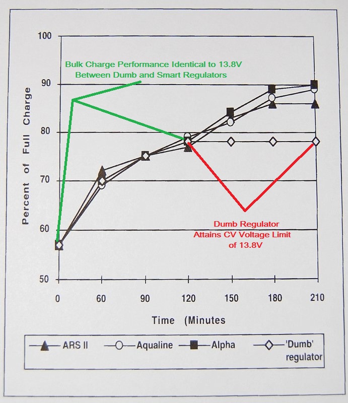
This graph below was done by Practical Sailor and illustrates the point of 14.4V is 14.4V or voltage is voltage rather well. Unfortunately there were a few flaws in their testing methodolgy.
The most glaring issue is that they compared a "dumb" regulator set to 13.8V to smart regulators set to 14.4V. This is NOT a fair comparison, or even very representative of today's stock alternators which almost always have higher voltage set points. This was a flawed testing protocol on the part of Practical Sailor.
Where the graph diverges, between dumb & smart, is when the batteries hit 13.8V volts. If the dumb reg had been set to 14.4V the graphs would be virtually identical all the way up. I've repeated this on my own bench and on my own boat.
I have used, installed and owned external regulators made by Sterling Power, Balmar, Heart Interface, Xantrex, Mastervolt and Ample Power. With a small flooded bank there is no reason a weekend sailor can't tough it out with a stock alternator. This is even true of "super dumb" regulators depending upon use. See, we keep rounding back to that word again, USE. How you use the boat, what type of batteries you have, average depth of discharge, and the size of the bank is how to best to attack alternator charging..
There's no secret sauce, voltage/pressure limits are voltage/pressure limits. There is lots of tremendous & very useful "secret sauce" features in an external performance regulator but 14.4V is 14.4V to the batteries no matter where it comes from.
The article this graph comes from is one reason why PS sometimes gets a bad rap for "less than in-depth" and a "less than fair" analysis. I am not pricking on PS here, I am actually a contributor/tester/writer for them, but you can't compare two UNEQUAL VOLTAGES and then claim "external regulators charge faster". Yep no kidding a pen, paper and Ohm's law tells us this.. There are a number of marine alternators out there, the Motorola/Prestolite/Leece-Neville 8MR series to name one, with simple 14.4V dumb regulators. As a point of reference I have not seen a 13.8 volt regulator on a newer engine in the last 18 + years.
A comparison like this is only good for those with antique alternators limited to 13.8 volts, of which there are still many out there. Mistakenly PS, for that article, chose an antiquated 13.8V model to compare to 14.4V. A fair or equal comparison...? No, not at all.
PS Graph
Misleading Marketing??
Some of the regulator manufacturers can be rather unscrupulous when it comes to "charge faster" claims. Some of them are comparing their product to old style regulators that used to have voltage target set points of 13.6 to 13.8 volts. Almost all new marine alternators come through at somewhere between 14.2 - 14.6V and have been shipping that way for the better part of 15-20 years. We should ask our selves why the regulator manufacturers have not published head to head comparisons between their product and dumb regulators that are monitored by an independent lab? Where are these white papers? Where is the science and data behind all the secret sauce? Don't hold your breath, we will NEVER see this, because as I said 14.4V is 14.4V is 14.4V no matter the voltage limiting source.
Many manufacturers also make claims like; "you can never achieve a full charge without external regulation". Well, in the pure sense of a sailboat, then yes. With a regulator set at 13.6V it will never fully charge the bank on the diminutive hours spent running the motor, but neither do smart regulators, when looking at average engine run times in sailboats.
Some external regulator manufacturers are more unscrupulous than others. One UK manufacturer is rather over the top in this regard. They have chosen voltage settings exceeding 15V, compared to 13.8V, in order to compare charging speed. Obviously a higher voltage / pressure will absolutely cause the bank to charge faster, but, again this is an unfair comparison to many of today's voltage set points. The battery can only take what it can take once it hits target voltage so we can't charge to full in teh time periods they are suggestion you can.
I love external regulation and stand behind it 150%, for the right application. I install a lot of external regulators and high performance alternators, when it is wise to do so. I am only urging you to do some leg work and figure out what you really need.
Boat Use Determines Charging System Needs:
Weekender / Day Sailor - Unfortunately a day sailor or weekender who does 40 motor hours per year on two group 27 batteries, who ties to a dock with shore charging after each weekend or day sail, is very often making a marketing based financial decision to spend $1000.00 +/- on a performance charging system, yet I see it all the time. Many times the performance charging system yields a poor financial to actual gain. It sure doesn't hurt anything to upgrade, except for your wallet.
Cruiser - A cruiser who spends lots of time away from the dock, deeply cycling the batteries, would be very wise to make a move to a higher performance charging system utilizing external regulation.
Mooring Sailed Vessel - A mooring sailed boat can almost always benefit from an alternator & regulator upgrade. First however, the owner should consider solar.
What's The Big Difference In A Few Volts ???:
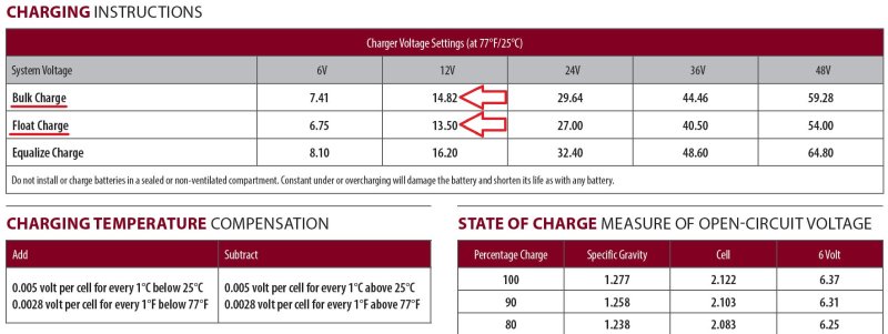
The difference between 13.6V & 14.6V does not seem like much but it is a BIG difference in terms of "flow" of current into the battery. At 13.8V a battery can often plateau and hit absorption at about 60-65%+/- SOC, depending upon age, the current source and condition of the battery, and will charge quite slowly beyond the absorption voltage if it is held low. In contrast the battery will charge faster the higher the voltage is set, but it should not be set not too high. For typical flooded lead acid batteries 14.4V to 14.8V is what is recommended by most battery makers. 14.9Vcan even be a short duration bump, not constant, and this can be done with an external regulator such as a Balmar.
For example you may set the BV voltage to 14.9V for 18 minutes than set the AV voltage to 14.8V for the duration. You could also set BV to 14.8V then AV to 14.7V. By setting the first target voltage a bit higher you get to a higher SOC faster. An internal regulator can't do this.
When talking about voltage differentials we need to consider that current will not even begin to flow into a battery until a voltage slightly above its resting voltage. So if your battery was at 12.4 volts and you flipped on the charger real current would not even begin to flow until above 12.4 volts. Consider about 0.1V above resting open circuit volts as the flow threshold where current begins flowing.
If you now compare a 13.6 volt limit to a 14.8V limit that is a HUGE percentage increase in charging pressure. Remember, in the above scenario the base line was at 12.4V volts not 0 volts. This difference in voltage is how external regulator companies began to make their "charge faster" claims. Remember, we are not starting at a baseline of 0 volts, we start this at about 0.1V higher than resting open circuit voltage. So, the difference in charge speed between 13.6V & 14.8V is actually quite dramatic. Comparing a regulator set to 13.6V to one set to 14.6V is like pitting Bode Miller against Janet Reno is a ski race, no comparison.
Note: If you have noticed over the last few years companies like Balmar are no longer focusing on "charge faster" claims and are focusing on the many other great features their regulators offer. They simply moved away from being a company that does quasi misleading marketing to one of feature/benefit selling. This is good news because the Balmar regulators have lots of tremendous benefits beyond the "charge faster" claims made early on.
"What Should I Do?"
Dumb Regulator Low Voltage - If you have an old 13.6V - 13.8V regulator, and wet cells, ditch it and get a regulator that is a minimum of 14.2V - 14.4V or even 14.6V and you will charge a lot faster. If you choose a different internal regulator, this is often an option, keep in mind that battery gassing generally begins above 14.3V. Of course the gassing voltage is temperature dependent, so a dumb regulator that does 14.5V - 14.6V will cause your flooded batteries to need water added more often. While 14.4V would be easier, maintenance wise, an absorption voltage of 14.6V - 14.8V will both charge even faster and is going to fend of sulfation better and be healthier for the flooded batteries.. If you are a coastal cruiser doing 40 engine hours per year, a new internal regulator (not a thermistor model) is an adequate compromise option. The best case here is to convert to external regulation if your alternator is large enough to make good use of it..
Dumb Regulator Set to +/- 14.4V - This can work adequately well provided you have minimal voltage drop in the system and it regulates to around 14.4V or so. While a single voltage regulator is less than ideal, especially, if you are not a full time cruiser, an arrangement like this can work adequately well for weekend boater.. Be aware that with a large bank you can literally burn up a dumb regulated alternator because it has no temperature protection circuitry.
Super Dumb Regulator - (temp compensated) If you tie to a dock after each sail and shore charge the bank, you can usually just keep this alternator. If you actually cruise, & deeply cycle the batteries, do yourself a favor and get rid of it.
Voltage Sensing Improvements: Many stock alternators can be set up or wired to provide external voltage sensing at the battery terminals as opposed to the back of the alternator itself..
Please do not try this if you don't know what you are doing. Any good alternator shop can help you wit this and it can make a big difference in charging performance. The only good way to get accurate voltage sensing is for the negative regulator lead and the positive sense lead to be direct wired to the battery bank.Voltage sensing is a circuit just like any other DC circuit. Moving only the positive sense only corrects for the positive side of the circuits voltage drop.
How Would I Measure The Voltage Set Point Of My Existing Regulator:
With the batteries at 100% state of charge run the engine and test the voltage output at the B+/Output terminal of your alternator with the DVM neg lead to the case or neg terminal of the alternator. The voltage should be somewhere between 14.2V & 14.4V but I would not go much above above 14.6V with a "dumb" regulator. Many regulators on Universal engines were factory set at 15.0V to try and compensate for the ammeter & horrible factory wiring.
Is Float Necessary On Sailboats?
In my opinion, mostly no. Emphasis on mostly.. Float for many sailboats is a tool best left to the trawler crowd who actually run their engines day in, day out for hours and hours on end. It is also a good option for those who choose expensive AGM or GEL batteries with higher acceptance rates getting you to "float" faster than wets will allow. If you plan however on doing the ditch it is a very good feature.
For the amount of time you, a sailor, are charging off an alternator, and the potential amount of hours spent at 13.2V - 13.6V float levels being so VERY, VERY limited, it may not be necessary for your boat to even have float for the alternator.. Unless your batteries have high acceptance rates, you motor for long periods or you also have an alternator that can deliver lots of amperage don't consider this a hugely critical requirement..Float is rarely going to be useful to you unless you are really a trawler with a stick. One of the problems with float and external regulators is one I call "premature floatulation". Owners and many techs rarely set up external regulators correctly and they drop to a float voltage far too soon, just as the lawyers want it to. As I mentioned earlier the "advanced programming" menue is in the Balmar regulators for a reason. Use it!
For solar controllers, or shore chargers float absolutely necessary. Float is a great a feature but less critical for alternator run times we often have on boats. Again, your use will determine if you need a float feature for your alternator.
"Did I over-think my system?"
In my opinion a a fair amount of coastal sailors/weekend boaters, with cheap flooded batteries, can over-think an alternator charging system.
With certain battery types though you really do need to address the system. The reality for me is that I see approx about 20% of the boats out there that have AGM, GEL or AGM TPPL batteries, yet a large portion of the weekend use boaters have an upgraded alternator charging systems. Many of them with no dire need. Money wasted? Some times yes, when based on actual use..
When Should I Use External Regulation?
Flooded Cell Batteries - If the bank exceeds the hot rated alternator capacity by more than 80% I recommend a smart regulator, temp sensing of both battery and alt and belt/amp manager. Eg; a 400 Ah bank can accept about 100 amps in bulk so a 70 amp alternator, using its hot rating, would get external regulation with alternator temp sensing at the least.
TIP: I generally install a larger amperage alternator than is desired for the design output. I then de-rate or limit the output of the alternator within the regulators settings. This allows the alternator to work less hard, run cooler, live a long happy life and be at much less risk of failing. De-rating the output of the alternator can be done with Balmar regulators. If I am sending a customer off shore it's a very rare case where I am allowing the alternator to be driven to 100% output by the regulator.
AGM- I always recommend external regulation with alternator and battery temp sensing at a minimum. I have seen a number of dumb regulated alternators burned down by the high acceptance rates of AGM batteries. Temp sensing of the batteries is a requirement for these expensive batteries.
GEL- I always use external regulation with alternator and battery temp sensing at a minimum. GEL's require specific voltage ranges that dumb regulators just can't accommodate very often. Battery temp sensing is a must with gels IMHO.
TPPL AGM's - Same as AGM
Dumb Regulator / Temp Compensated (Hitachi/Yanmar etc.) - These alternator regulators are horrible for deep cycling applications. IMHO nearly every Yanmar engine with a Hitachi alternator, if used regularly in a deep cycling application, should have it converted to external regulation or convert to a new alt & regulator.
Dumb Regulator / Low Voltage Set Point - If your alternator regulator is set to less than 14.2V it would be wise to invest in a better regulator.
Inaccurate Voltage Sensing - This piece can not be over looked. Many factory systems have horrendous voltage drop between the battery bank and alternator. These alternators are also "self sensed" meaning they measure system voltage at the alternator BEFORE ANY VOLTAGE DROP.... This can cause the alternator to go into CV / voltage limiting mode prematurely. External regulators correct for this by allowing positive and negative regulator wires (volt sensing) to be routed directly to the battery terminals. This can yield significant charging performance increases..
Summary:
In short, smart regulators most definitely do have a place on cruising sailboats & they are tremendous tools. However the use should ideally be well justified for the expense laid out. The installation of a smart regulator should be considered in the total system design. Their use is very often justifiable, but occasionally it's not, especially for a weekend use coastal cruiser.
The average small bank of flooded batteries, for a weekend cruiser, does not absolutely require a $1500.00 + charging system when a simple regulator, with the proper voltage setting, will work suitably well. In my experience a good battery monitor, properly programmed, or another way to monitor SOC performance, such as the Balmar Smart Gauge, should be the first place to start your upgrading. If the SOC is telling you you're not meeting charging performance you desire then by all means address it.
Hope this was a somewhat helpful topic on alternator regulation.
P.S. I love this quote from Balmar
Quote From Balmar:
"Forget the rumor that an oversized alternator will destroy your batteries ... the truth is that the acceptance rate of your batteries will dictate how much amperage the alternator will provide."
If you want to avoid the diatribe below: In almost all cases an external regulator will yield a better performing charging system, but it may not make "financial sense" for your particular use.
The choice of external vs. internal should ideally be based on:
- Your use of the boat
- Your battery bank size
- Your battery bank chemistry (Flooded, GEL, AGM, TPPL AGM, LiFePO4)
- How much time you are willing to run the motor each day
I am making a LOT of general assumptions below so be patient:
1- Voltage is the pressure that cause the batteries to accept current.
2 - Amps are the "flow" and the higher the pressure/volts the more the flow/current can be.
3 - The alternator is not "forcing" or dictating amps to a battery, it does not do this, the battery "accepts" or lets current flow, based on voltage at the battery terminals and SoC.
4 -The alternator provides the current up to what it can provide or the battery can accept at XX.XX volts. Prior to the battery reaching the absorption voltage the alternator is basically *full throttle providing all the current it possibly can.
*Unless the regulator uses a temp gradient type regulator.
5 - A voltage regulator is little more than a VOLTAGE LIMITER. All it really does is LIMIT or maintain a preset voltage once the battery bank gets to the target voltage. External high performance regulators can limit voltage based on battery temp, alternator temp, time at voltage & other parameters but they still limit voltage.
Temperature compensation of the alternator and batteries is one of the most useful features of external smart regulators. Voltage limiting or voltage regulation modifies the alternators field voltage/current to maintain the desired set point voltage. This regulation technique is called pulse width modulation. Simply put the on time and off times are modulated at insane speeds in order to maintain the desired voltage set point the regulator wants to see or is limiting voltage to.
If the voltage starts to creep up the PWM or off time to the alternator field gets extended. Cutting back the alternators field via PWM, limits the current the alternator can produce and thus a voltage limit is maintained and voltage over-shoot is prevented. Good quality external regulators can control voltage to within a 10mV to 30mV range or 0.01V to 0.03V.
If you add a big load the regulator will boost the fields on time to maintain the voltage set point. PWM all happens so fast that you need an Oscilloscope to even begin to see it. If the load exceeds what the alternator can produce, eg: a bow thruster, the regulator reverts to full field or 100% output. Voltage limiting and PWMing of the field go hand in hand.
6 - A typical voltage regulator has no clue what the amperage is coming our of the alternator. All the regulator knows is voltage, hence the term voltage regulator. Voltage regulators regulate based on voltage not amperage. While the amperage out of the alternator changes up & down to maintain a voltage set point the regulator is doing all of this all based on voltage.
7 - The internal resistance of a battery (SoC) determines the current it "accepts" or takes from the alternator to maintain a voltage at a specific state of charge.
With a small alternator, in bulk mode, the alternator will be limited to what it can physically produce, while hot. What it can produce is based on RPM and alternator winding temperature. Bulk just means "full field" or that the alternator voltage sense circuits has still not attained the pre-set voltage limit of the regulator. This stage of charging is called BULK or constant current (CC). In Europe, under DIN standards, they often call bulk charge a BOOST.
The relation ship of alternator current to banks size also plays a role. A small alternator attains the CV stage voltage limit at a higher SOC. Conversely, if you have a very large amperage alternator, the bulk period will be shorter and the battery bank will attain the voltage limit (CV stage) at a lower overall SOC. With a large source of current a battery can come up to absorption voltage more quickly because the battery can not accept the current, into the battery plates, as fast as the source can provide it. This builds a surface charge on the plates and results in driving the voltage up faster than a smaller current source.
8 - Let's address charging lingo such as *Bulk, *Absorption & Float.
FACT: Both smart and dumb regulators do both bulk (CC) and absorption (CV) or CC/constant current & CV/constant voltage stages.
BULK / CC - Bulk charging is essentially applying the max field the alternator rotor in both smart and dumb regulators. Bulk charging is any period of time before the regulator has attained it's absorption voltage limit at the battery terminal, or alternator, if "voltage sensed" there. In the bulk stage the alternator is delivering the maximum current it that it can based on copper temperature and rotor RPM. How much is needed to drive each alternator depends upon the specific alternator. Many alternators can pump out 100% of their rating with a field voltage of less than half that of the battery bank voltage, while others require 8-9V and massive 350A+ alternators may require upwards of 10-11V.
As a battery charges during bulk its terminal voltage gradually rises. If the regulator, smart or dumb, has been set to 14.4v then until the batteries hit 14.4v is considered bulk charging. Bulk charging is also called constant current charging meaning the charge source, in this case an alternator, is supplying all the current that it physically can at its current temperature and RPM.. Bulk is where the maximum current will flow into the battery because the batteries internal resistance is low due to being discharged.
During bulk charging the differential in pressure or voltage is at its greatest and thus the battery is accepting all the current the alternator can feed it as the terminal voltage slowly rises.
ABSORPTION / CV - Once the battery attains the voltage limit the regulator switches from the bulk/constant current stage to the absorption/constant voltage stage and begins regulating to the voltage limit.
Once the voltage is held steady or becomes voltage limited the current being accepted by the battery begins to decrease. This is because the regulator is now operating in CV or constant voltage mode and as SOC rises the battery needs or accepts less and less current in order to maintain & not over shoot the voltage limit.
FLOAT/CV - Float voltage is a further reduced constant voltage limit applied by a smart regulator. Dumb regulators do not do a true float. If you feel you need float, because you motor a lot more than you sail, you's want a smart external regulator.
All of the above is based on what I have seen, read or heard most people misconstrue. You may not have misconstrued any of it but it is good to get out there.
Marketing Mumbo Jumbo: Just because companies such as Balmar call "bulk" (BV) a voltage limited stage of charging, the simple answer is that this is not true. Charge product manufacturers that do this, and we are a large Balmar dealer, are simply using incorrect terminology. Some companies do this purposely to confuse & confound the customer into thinking they are getting more. In teh case of Balmar the EE who designed the regulator used three CV stages and one CC stage. He called the first CV stage BV or Bulk Voltage, the second stage AV or Absorption Voltage and the third FV or Float Voltage. Seeing as Balmar was the first to have two absorption level voltages this seemed to make sense.
Of course, this is really all just marketing and we live with it every day. Bulk charging is constant current or when related to an alternator constant potential based on heat and rotor RPM. Bulk is simply not a constant voltage stage. In recent years more and more companies have begun using the incorrect terminology of "bulk voltage". You can have a bulk transition voltage, the point at which it transitions to absorption, but you can't really have bulk voltage that is constant voltage.
During bulk charging the battery voltage is ALWAYS on the RISE thus it can not be a "bulk constant voltage".. More appropriate terminology, as related to products such as the Balmar regulators might be Absorption 1 & Absorption 2.
As mentioned above I know why Michael, the designer of the Balmar regulators, named it bulk voltage. I had long conversations with Michael, including discussions specifically about terminology, and he admitted it was an incorrect use of terminology that just got adopted by the marketing department. Of course, at the time, with a regulator that had 15,000 lines of code, correct industry accepted and defined terminology was far from the first thing on his mind.
- Bulk = Constant Constant or Constant Potential Charging
- Absorption = Constant Voltage Charging
- Float and Equalization = Constant Voltage Charging
At the bulk to absorption transition voltage the regulator begins PWMing the field wire in order to maintain the pre-set voltage limit. With an adequately sized alternator this is often stated & repeated as a state of charge (SOC) of somewhere around 80% SOC. This however is not always a truism.
The SOC at which you attain absorption voltage is entirely dependent upon how much charging current you have. With a small solar array, you may not hit absorption voltage until 96% SOC and with a massive alternator you may hit absorption at 65% SOC. The point at which your battery bank attains the voltage limit is entirely depending upon how much current you have available. On top of current availability sulfation, battery state of health and *incorrect voltage sensing, among others, will change the point at which the battery attains the CV/voltage limit.
*Accurate voltage sensing is critically important on sailboats that desire short engine run times. Factory alternators do a horrible job with this. For more in-depth discussion on this subject see: Alternators and Voltage Sensing Why It's Important
Sulfation & SOH Impact Bulk Charge Time:
A sulfated battery or a battery in poor state of health (SOH)will quickly rise to absorption voltage despite not yet actually being charged. Simply put until a battery reaches the voltage limiting set point, absorption charging, all regulators, smart or dumb, simply "*full field" the alternator to what ever the regulator can produce in field voltage/ field current. Battery chargers and solar controllers operate the same way.
If your battery bank starts out at 50% SOC and you;re attaining the voltage limit in a short period of time the battery is likely shot. At a charge rate of .2C, or 20% of Ah capacity in charge current, it should take an hour or more to attain the absorption voltage limit.
*The exception is an alternator with a thermistor/temp gradient regulator.
Can Internal "Dumb" Regulators Really Do Bulk Charging?
Yes they absolutely can, though there are certain things that can impact just how well they do this compared to an external regulator.
The question below was posed on an external alternator regulator manufacturers web site. This company builds smart external regulators and alternators.
Question:
As I understand it most of the regulators regulate voltage not amperage? Before the regulator hits the absorption set point, mine is 14.4 volts, they are simply full fielding the alternator. So do both dumb and smart regulators do the same to the alternator, apply full field until the absorption voltage is reached?
Answer from Manufacturer:
You're correct, during the bulk phase, the alternator is 'full fielded', by all regulators. But the term 'full fielded' is loosely defined as applying the maximum voltage that can be applied by the regulator. If you measure the voltage drop between B+ and field during the bulk cycle you'll find that an XXXXX Regulator drops the least voltage of any regulator. More voltage on the field means more Amps.
While the external regulator can produce a higher field potential, is this always necessary? The answer is no, it is not always necessary. We should consider that an external regulator must be able to drive any alternator it is fitted to, and it will need the capability to deliver a wider range of field potential to any alternator out there. External regulators can deliver upwards of 15A to drive the field. An internal "dumb regulator" only needs to produce enough field potential to drive the specific alternator it was designed to be fitted on in order to attain its maximum output rating. For some alternators this may require as little as 4A. There is no reason for Delco, Bosch, Paris Rhone, Leece-Neville etc. to design an internal regulator capable of 15A when the alternator is only needing 4A to attain its full output. In industry pennies count. A general fit external regulator must be able to drive any alternator so they are built to do this. While the statement above is technically true it is misleading at best.
A few years ago I spent an entire Saturday at a friends shop conducting experiments with many different internal dumb regulated alternators. This shop has a $30,000.00 alternator testing machine I got to play with for hours.. I loaded random internally regulated alternators into the machine and tested them for max alternator rated output.
Bottom Line? Every single internal dumb regulator applied enough field voltage/current to achieve the max rated output of the alternator, every one. Keep in mind however this was "cold testing" and as some alternators heat up they reduce the voltage limit based on internal thermistors. I will get to this later.
While you may be able to apply more field potential, as most external regulators have the ability to, you can't exceed the alternators physical capabilities. If the alternator can hit its maximum output rating with a *dumb regulator, then a smart one, set to the same voltage and sensed at the same spot, will not increase charging times in bulk stage.
*Excludes thermistor equipped/temp gradient internal regulators
This video may help pull some of the above together:
Let's Put This Into Practice:
*If you take two identical 100 amp alternators and two identically discharged battery banks and one smart and one dumb regulator (truly dumb, no thermistor), and they both sense voltage at the same point in the system, they will both charge at the same speed in bulk. No magic here just basic Ohm's law stuff. Full field is full field.
*Assumes everything is the same except the regulators.
The bottom line truth is an *external regulator will not charge faster if the voltages are set equal and the set up and wiring is the same. (*non-thermistor type)
External Regulation Instillation Practices Matter:
The sad reality is that the vast majority of external regulators I see installed are almost always set up to physically charge slower than they can. Due to improper programming and incorrect installation practices they enter float far to early in the charge curve. This robs owners of the charging performance they paid for. The "advanced programming" menu is Balmar regulators is there for a reason! The temps sensors are sold for a reason!
External regulators WILL DEFINITELY charge faster if you set them up correctly using the correct absorption voltage for your batteries. You push absorption voltage higher with an external regulator because you have a float feature after a high absorption voltage. You would not want a high absorption voltage setting, actually the only CV setting, on a "dumb" regulator.
When you dumb it down there is nothing fancy about voltage regulation/voltage limiting or PWM control of the alternators field. Smart regulators do not charge faster, when set at the same voltage set point, and all other things being equal because a battery is only going to accept what it can accept at a specific voltage and SOC.
The battery really has no clue it is hooked up to a $400.00 external regulator or a $15.00 internal regulator, all is knows is the voltage at its terminals and how much current it will accept at that SOC and at that voltage. Course if your internal regualtor is set for 14.6V and you motor down the ICW for 10 hours per day you're going to be adding water to the batteries quite often. If you do this with AGM or GEL the batteries will be getting over charged.
External regulators can be set up to charge faster and to maximize the alternators output. This only works if you set them up properly for your battery type. Sadly many installers or DIY's don't set them up this way. I would estimate that a solid 80% of the external regulators I see are still on the UFP (universal factory program) setting.. This gains you little to no benefit over a *dumb regulator in charging speed.. (*truly dumb no thermistor)
Why Do Internal Regulators Get Such a Bad Rap:
#1 Voltage sensing - Most internal internal regulators sense voltage at the back of the alternator, not at the battery terminals. The factory wiring between the batteries and alternator can induce substantial voltage drops causing the batteries to charge slow and hit limiting voltage far earlier than they should.
#2 Internal Regulator Temp Gradients - Some dumb regulators are what I often refer to as "Super Dumb". By this I mean the alternator protects itself by reducing the regulation voltage as it heats up. This serves to protect the alternator, smart for the alternator, but super dumb for deep cycle batteries. There are better ways to keep the alternator from running too hot than a thermistor protected regulator.
For a more in-depth look at this subject see here: Automotive Alternators vs. Deep Cycle Batteries
#3 Low Voltage Fixed Limit Point - Some alternators have an absorption voltage set point that is far too low, below 14.4V. Combine this with inaccurate voltage sensing & a temp gradient and you have really, really $hitty charging performance.
Are All "Dumb Regulators" The Same?
No, they are not.
Dumb:
A simple dumb regulator has but one voltage set point and that is it. It can do Bulk/Constant Current or *Constant Potential (*accounts for heat and RPM) and Absorption/Constant Voltage. If this set point is 14.4V you 're going to do okay if you're a weekend sailor with a small bank who ties to dock charging during the week. This also assumes you have minimal voltage drop between the alternator and batteries. If you move to a large bank that spends a long time in bulk these alternators can and do literally burn themselves up. I replace or rebuild approximately 5-15 alternators each year that have physically burned up from spending too much time in bulk and being chronically over-worked.
Super Dumb:
Hitachi/Yanmar, Valeo, Mitsubishi, Bosch & most newer auto-based alternators are dumber than a pound of beetle-crap to install on a boat with a deep-cycling battery bank. To the alternator or car batteries they are pretty smart but to your deep cycle batteries, and the negative impact in relation to actually charging them in a healthy manner, they are flat out stupid.
Why? Hitachi & many other automotive alternators with internal regulators, limit voltage but they also reduce voltage based on alternator temperature. They usually accomplish this using internal thermistors in the voltage regulation circuitry. In a deep cycle application this amounts to a self protective feature to try and prevent the alternator from cooking itself. In automobiles this type of circuitry is a cheap way to minimize the over charging a car battery in a hot engine compartment. Due to often super high automobile engine bay temps this thermistor reduces output voltage to a safer level. On a boat however, the batteries are not in the engine bay, or should not be, so the thermistors heat sensitivity is driven by how hard the alternator is working and the heat generated by the alternator itself from being worked hard in bulk. Remember voltage is the pressure so by reducing the limit voltage, we also reduce the current that can flow into the batteries and chop charging performance dramatically.
On boats battery temp sensing should be done directly at the battery, not inside the alternator. If you want to protect the alternator then reducing the field, not the regulated output voltage, is the proper method with a deep cycling bank. If we reduce the voltage limit, then we also reduce the current the alternator is supplying to the battery. Add in some voltage drop and we now have an 80A alternator only capable of as low as 20-30A in bulk..... The thermistor protection is good for the alternator, and it usually gets the manufacturer through the warranty period, but it is horrible for your deep cycle batteries.
The battery simply will not accept the same current at 13.4V that it did at 14.4V. As a result the alternator will run cooler but the battery will charge at a snails pace. What do you suppose this chronic under charging does to your batteries over time.......?
The behavior is that when cold you will get 14.3V to 14.4V out of the "super dumb" regulator but as the alternator heats up the "super-dumb" regulator begins to reduce the CV/voltage limit based on the alternators internal temperature. It is not uncommon to find a Hitachi alternator at 13.4V when hot. This is really, really, really bad for your deep cycle batteries.
If you have a super dumb regulator, and notice the voltage dropping, or not climbing and current output abysmal,it is likely a thermistor protected dumb regulator.
Super Dumb Rx = Get rid of it or plan to buy new batteries more often. If you have a temp compensated automotive type alternator you are really in dire need of external regulation if deep cycling a larger battery bank. I do not recommend converting these stock alternators, below 80A, to external regulation because the amount of current limiting required to get them to run at a safe temp makes them nearly useless in terms of charging current.
"So if I have a basic dumb regulator at 14.4V, with no thermistor gradient, it can charge at the same speed as an external regulator?"
Yes it potentially can, but ONLY if everything is the same including voltage sensing. This is not what you will hear on the docks especially from owners who have gone from internal to external because they have not done a fair or equal comparison. The caution here is that as you grow your bank size you run a much higher risk of burning out the dumb regulated alternator. On top of that flooded and many AGM batteries need to be charged and higher voltages than 14.4V for optimal service life..
But I am just a weekend sailor?
Many boat owners, when upgrading an alternator system, also upgrade the battery bank and or alternator & wiring at the same time so the performance claims can be misguided & often misunderstood. This is not an equal or a fair comparison to their old alt or bank or an equal baseline measurement from which to draw a fair conclusion.
Thus, the industry marketing works and boat owners believe that an external regulators will always charge their bank faster. Based on how I see them incorrectly set up, this is simply very often not true. While true for some, compared to their old system, this is not always true, in every situation, or with every brand of external regulator. As a weekend sailor with a small bank, starting our from 100% SOC each weekend, and a dumb regulator set at 14.4V, your performance gains may not be worth the cost outlay to go to external regulation.
Fair Comparisons:
This graph below was done by Practical Sailor and illustrates the point of 14.4V is 14.4V or voltage is voltage rather well. Unfortunately there were a few flaws in their testing methodolgy.
The most glaring issue is that they compared a "dumb" regulator set to 13.8V to smart regulators set to 14.4V. This is NOT a fair comparison, or even very representative of today's stock alternators which almost always have higher voltage set points. This was a flawed testing protocol on the part of Practical Sailor.
Where the graph diverges, between dumb & smart, is when the batteries hit 13.8V volts. If the dumb reg had been set to 14.4V the graphs would be virtually identical all the way up. I've repeated this on my own bench and on my own boat.
I have used, installed and owned external regulators made by Sterling Power, Balmar, Heart Interface, Xantrex, Mastervolt and Ample Power. With a small flooded bank there is no reason a weekend sailor can't tough it out with a stock alternator. This is even true of "super dumb" regulators depending upon use. See, we keep rounding back to that word again, USE. How you use the boat, what type of batteries you have, average depth of discharge, and the size of the bank is how to best to attack alternator charging..
There's no secret sauce, voltage/pressure limits are voltage/pressure limits. There is lots of tremendous & very useful "secret sauce" features in an external performance regulator but 14.4V is 14.4V to the batteries no matter where it comes from.
The article this graph comes from is one reason why PS sometimes gets a bad rap for "less than in-depth" and a "less than fair" analysis. I am not pricking on PS here, I am actually a contributor/tester/writer for them, but you can't compare two UNEQUAL VOLTAGES and then claim "external regulators charge faster". Yep no kidding a pen, paper and Ohm's law tells us this.. There are a number of marine alternators out there, the Motorola/Prestolite/Leece-Neville 8MR series to name one, with simple 14.4V dumb regulators. As a point of reference I have not seen a 13.8 volt regulator on a newer engine in the last 18 + years.
A comparison like this is only good for those with antique alternators limited to 13.8 volts, of which there are still many out there. Mistakenly PS, for that article, chose an antiquated 13.8V model to compare to 14.4V. A fair or equal comparison...? No, not at all.
PS Graph
Misleading Marketing??
Some of the regulator manufacturers can be rather unscrupulous when it comes to "charge faster" claims. Some of them are comparing their product to old style regulators that used to have voltage target set points of 13.6 to 13.8 volts. Almost all new marine alternators come through at somewhere between 14.2 - 14.6V and have been shipping that way for the better part of 15-20 years. We should ask our selves why the regulator manufacturers have not published head to head comparisons between their product and dumb regulators that are monitored by an independent lab? Where are these white papers? Where is the science and data behind all the secret sauce? Don't hold your breath, we will NEVER see this, because as I said 14.4V is 14.4V is 14.4V no matter the voltage limiting source.
Many manufacturers also make claims like; "you can never achieve a full charge without external regulation". Well, in the pure sense of a sailboat, then yes. With a regulator set at 13.6V it will never fully charge the bank on the diminutive hours spent running the motor, but neither do smart regulators, when looking at average engine run times in sailboats.
Some external regulator manufacturers are more unscrupulous than others. One UK manufacturer is rather over the top in this regard. They have chosen voltage settings exceeding 15V, compared to 13.8V, in order to compare charging speed. Obviously a higher voltage / pressure will absolutely cause the bank to charge faster, but, again this is an unfair comparison to many of today's voltage set points. The battery can only take what it can take once it hits target voltage so we can't charge to full in teh time periods they are suggestion you can.
I love external regulation and stand behind it 150%, for the right application. I install a lot of external regulators and high performance alternators, when it is wise to do so. I am only urging you to do some leg work and figure out what you really need.
Boat Use Determines Charging System Needs:
Weekender / Day Sailor - Unfortunately a day sailor or weekender who does 40 motor hours per year on two group 27 batteries, who ties to a dock with shore charging after each weekend or day sail, is very often making a marketing based financial decision to spend $1000.00 +/- on a performance charging system, yet I see it all the time. Many times the performance charging system yields a poor financial to actual gain. It sure doesn't hurt anything to upgrade, except for your wallet.
Cruiser - A cruiser who spends lots of time away from the dock, deeply cycling the batteries, would be very wise to make a move to a higher performance charging system utilizing external regulation.
Mooring Sailed Vessel - A mooring sailed boat can almost always benefit from an alternator & regulator upgrade. First however, the owner should consider solar.
What's The Big Difference In A Few Volts ???:
The difference between 13.6V & 14.6V does not seem like much but it is a BIG difference in terms of "flow" of current into the battery. At 13.8V a battery can often plateau and hit absorption at about 60-65%+/- SOC, depending upon age, the current source and condition of the battery, and will charge quite slowly beyond the absorption voltage if it is held low. In contrast the battery will charge faster the higher the voltage is set, but it should not be set not too high. For typical flooded lead acid batteries 14.4V to 14.8V is what is recommended by most battery makers. 14.9Vcan even be a short duration bump, not constant, and this can be done with an external regulator such as a Balmar.
For example you may set the BV voltage to 14.9V for 18 minutes than set the AV voltage to 14.8V for the duration. You could also set BV to 14.8V then AV to 14.7V. By setting the first target voltage a bit higher you get to a higher SOC faster. An internal regulator can't do this.
When talking about voltage differentials we need to consider that current will not even begin to flow into a battery until a voltage slightly above its resting voltage. So if your battery was at 12.4 volts and you flipped on the charger real current would not even begin to flow until above 12.4 volts. Consider about 0.1V above resting open circuit volts as the flow threshold where current begins flowing.
If you now compare a 13.6 volt limit to a 14.8V limit that is a HUGE percentage increase in charging pressure. Remember, in the above scenario the base line was at 12.4V volts not 0 volts. This difference in voltage is how external regulator companies began to make their "charge faster" claims. Remember, we are not starting at a baseline of 0 volts, we start this at about 0.1V higher than resting open circuit voltage. So, the difference in charge speed between 13.6V & 14.8V is actually quite dramatic. Comparing a regulator set to 13.6V to one set to 14.6V is like pitting Bode Miller against Janet Reno is a ski race, no comparison.
Note: If you have noticed over the last few years companies like Balmar are no longer focusing on "charge faster" claims and are focusing on the many other great features their regulators offer. They simply moved away from being a company that does quasi misleading marketing to one of feature/benefit selling. This is good news because the Balmar regulators have lots of tremendous benefits beyond the "charge faster" claims made early on.
"What Should I Do?"
Dumb Regulator Low Voltage - If you have an old 13.6V - 13.8V regulator, and wet cells, ditch it and get a regulator that is a minimum of 14.2V - 14.4V or even 14.6V and you will charge a lot faster. If you choose a different internal regulator, this is often an option, keep in mind that battery gassing generally begins above 14.3V. Of course the gassing voltage is temperature dependent, so a dumb regulator that does 14.5V - 14.6V will cause your flooded batteries to need water added more often. While 14.4V would be easier, maintenance wise, an absorption voltage of 14.6V - 14.8V will both charge even faster and is going to fend of sulfation better and be healthier for the flooded batteries.. If you are a coastal cruiser doing 40 engine hours per year, a new internal regulator (not a thermistor model) is an adequate compromise option. The best case here is to convert to external regulation if your alternator is large enough to make good use of it..
Dumb Regulator Set to +/- 14.4V - This can work adequately well provided you have minimal voltage drop in the system and it regulates to around 14.4V or so. While a single voltage regulator is less than ideal, especially, if you are not a full time cruiser, an arrangement like this can work adequately well for weekend boater.. Be aware that with a large bank you can literally burn up a dumb regulated alternator because it has no temperature protection circuitry.
Super Dumb Regulator - (temp compensated) If you tie to a dock after each sail and shore charge the bank, you can usually just keep this alternator. If you actually cruise, & deeply cycle the batteries, do yourself a favor and get rid of it.
Voltage Sensing Improvements: Many stock alternators can be set up or wired to provide external voltage sensing at the battery terminals as opposed to the back of the alternator itself..
Please do not try this if you don't know what you are doing. Any good alternator shop can help you wit this and it can make a big difference in charging performance. The only good way to get accurate voltage sensing is for the negative regulator lead and the positive sense lead to be direct wired to the battery bank.Voltage sensing is a circuit just like any other DC circuit. Moving only the positive sense only corrects for the positive side of the circuits voltage drop.
How Would I Measure The Voltage Set Point Of My Existing Regulator:
With the batteries at 100% state of charge run the engine and test the voltage output at the B+/Output terminal of your alternator with the DVM neg lead to the case or neg terminal of the alternator. The voltage should be somewhere between 14.2V & 14.4V but I would not go much above above 14.6V with a "dumb" regulator. Many regulators on Universal engines were factory set at 15.0V to try and compensate for the ammeter & horrible factory wiring.
Is Float Necessary On Sailboats?
In my opinion, mostly no. Emphasis on mostly.. Float for many sailboats is a tool best left to the trawler crowd who actually run their engines day in, day out for hours and hours on end. It is also a good option for those who choose expensive AGM or GEL batteries with higher acceptance rates getting you to "float" faster than wets will allow. If you plan however on doing the ditch it is a very good feature.
For the amount of time you, a sailor, are charging off an alternator, and the potential amount of hours spent at 13.2V - 13.6V float levels being so VERY, VERY limited, it may not be necessary for your boat to even have float for the alternator.. Unless your batteries have high acceptance rates, you motor for long periods or you also have an alternator that can deliver lots of amperage don't consider this a hugely critical requirement..Float is rarely going to be useful to you unless you are really a trawler with a stick. One of the problems with float and external regulators is one I call "premature floatulation". Owners and many techs rarely set up external regulators correctly and they drop to a float voltage far too soon, just as the lawyers want it to. As I mentioned earlier the "advanced programming" menue is in the Balmar regulators for a reason. Use it!
For solar controllers, or shore chargers float absolutely necessary. Float is a great a feature but less critical for alternator run times we often have on boats. Again, your use will determine if you need a float feature for your alternator.
"Did I over-think my system?"
In my opinion a a fair amount of coastal sailors/weekend boaters, with cheap flooded batteries, can over-think an alternator charging system.
With certain battery types though you really do need to address the system. The reality for me is that I see approx about 20% of the boats out there that have AGM, GEL or AGM TPPL batteries, yet a large portion of the weekend use boaters have an upgraded alternator charging systems. Many of them with no dire need. Money wasted? Some times yes, when based on actual use..
When Should I Use External Regulation?
Flooded Cell Batteries - If the bank exceeds the hot rated alternator capacity by more than 80% I recommend a smart regulator, temp sensing of both battery and alt and belt/amp manager. Eg; a 400 Ah bank can accept about 100 amps in bulk so a 70 amp alternator, using its hot rating, would get external regulation with alternator temp sensing at the least.
TIP: I generally install a larger amperage alternator than is desired for the design output. I then de-rate or limit the output of the alternator within the regulators settings. This allows the alternator to work less hard, run cooler, live a long happy life and be at much less risk of failing. De-rating the output of the alternator can be done with Balmar regulators. If I am sending a customer off shore it's a very rare case where I am allowing the alternator to be driven to 100% output by the regulator.
AGM- I always recommend external regulation with alternator and battery temp sensing at a minimum. I have seen a number of dumb regulated alternators burned down by the high acceptance rates of AGM batteries. Temp sensing of the batteries is a requirement for these expensive batteries.
GEL- I always use external regulation with alternator and battery temp sensing at a minimum. GEL's require specific voltage ranges that dumb regulators just can't accommodate very often. Battery temp sensing is a must with gels IMHO.
TPPL AGM's - Same as AGM
Dumb Regulator / Temp Compensated (Hitachi/Yanmar etc.) - These alternator regulators are horrible for deep cycling applications. IMHO nearly every Yanmar engine with a Hitachi alternator, if used regularly in a deep cycling application, should have it converted to external regulation or convert to a new alt & regulator.
Dumb Regulator / Low Voltage Set Point - If your alternator regulator is set to less than 14.2V it would be wise to invest in a better regulator.
Inaccurate Voltage Sensing - This piece can not be over looked. Many factory systems have horrendous voltage drop between the battery bank and alternator. These alternators are also "self sensed" meaning they measure system voltage at the alternator BEFORE ANY VOLTAGE DROP.... This can cause the alternator to go into CV / voltage limiting mode prematurely. External regulators correct for this by allowing positive and negative regulator wires (volt sensing) to be routed directly to the battery terminals. This can yield significant charging performance increases..
Summary:
In short, smart regulators most definitely do have a place on cruising sailboats & they are tremendous tools. However the use should ideally be well justified for the expense laid out. The installation of a smart regulator should be considered in the total system design. Their use is very often justifiable, but occasionally it's not, especially for a weekend use coastal cruiser.
The average small bank of flooded batteries, for a weekend cruiser, does not absolutely require a $1500.00 + charging system when a simple regulator, with the proper voltage setting, will work suitably well. In my experience a good battery monitor, properly programmed, or another way to monitor SOC performance, such as the Balmar Smart Gauge, should be the first place to start your upgrading. If the SOC is telling you you're not meeting charging performance you desire then by all means address it.
Hope this was a somewhat helpful topic on alternator regulation.
P.S. I love this quote from Balmar
Quote From Balmar:
"Forget the rumor that an oversized alternator will destroy your batteries ... the truth is that the acceptance rate of your batteries will dictate how much amperage the alternator will provide."