

More rigging horror.
- Thread starter Roger Long
- Start date
- Status
- Not open for further replies.
Looking back at the original design I see that is what they thought also. Probably a reason we came to the same conclusion.

Certainly, and it wouldn't be appropriate in all design situations. However, this is a fairly lightly loaded part needing to be sized for the material left on each side of the pin hole in order not to get into the kind of thickness changes which might be dictated in a very weight critical design.you do know that you have asymmetricly loaded the longer (right) tang, right?
At the breaking strength of the rigging the boat currently has, the neck would only be loaded to 25,300 psi. That leaves a lot left over to deal with the asymmetry. I'm increasing wire sizes 1/32" not because of overall rigging strains but to increase life.
The aft lowers don't carry a lot of tension when my boat is tuned up compared to forward ones. They mostly just help the mast stay in column. The reason why this design is not reversed is to have the more robust portion on the forward lowers.
One of the problems with the existing tanks is that they can actually lie in a straight line. They want to overlap. I now understand no the strange noises I've been hearing from that part of the rig when the boat heels well down.
Separate tangs, because of clearance issues not fully clear on the drawing, run into worse symmetry issues just below the main attachment where they do become critical and are complicated by the bend.
Well OK, I think you are going to find that only the area on the right hand side of the load line (left tang) is actually going to be doing the work.
Your boat, your choice.
Your boat, your choice.
Looking at a crude worst case, the offset between the centroid of the neck and the straightline between the pins would produce a bending moment of 863 in-lbs at the design wire B.S. That comes out to 37,690 psi at the narrowest part of the neck. Superimposed on the nominal wire B.S., stress would be 42,390. I think I can live with that. There is a straight line between the pin and mounting bolt so actual stresses would likely be lower. The area symmetric on each side of the pin to pin line, if I trimmed back the left side to make the fitting symmetrical, would give a stress of 50,620 when the wire breaks, less than ideal for a tang but sufficient for a partially redundant portion of the rigging.I think you are going to find that only the area on the right hand side of the load line (left tang) is actually going to be doing the work.
When I get the actual fittings in my hand, I'll reduce the cut out to the minimum.
Remember that blowing the boat flat in the water doesn't bring the wires anywhere near B.S. anytime during the knockdown. Greater stresses will be wave induced during a rollover which the rig isn't likely to survive anyway because the loads go beyond anything that can be designed for in a boat of this type.

Roger, with such a questionable rig and rig design, rather than keep throwing all this time and money making custom parts, why don't you just get a new mast with proper design for the standing rigging and then you can be happy again? I'm at the point where even I can't sleep at night worrying about you with this questionable rigging. I can only imagine the stress and anxiety you must be feeling.
By the way, plasma cutting is great but will leave a recast layer on the edges of the part. This recast layer will not have the same mechanical properties or material allowables as the rest of the material. It will often be brittle due to the melting and rapid solidification and cooling (quenching). Since the highest loads will be carried on the outside surfaces it will make failure due to fracturing more probable. I'd suggest if you use plasma that you follow up with a secondary process step to remove the recast layer by milling or grinding off several mils of material on each edge and liberally break the edges to provide nice radiuses. Wire EDM will be better with a much smaller recast layer and better surface finish and dimensional accuracy. Better yet would be to mill it out of sheet stock with a CNC mill so no recast layer at all. A CNC punch press, sometimes called a nibbler, is another option. Water jet is another readily available process that would do a nice job on this. The pin holes should be drilled and reamed and if possible roller burnished with a cogsdill roller burnishing tool.
PS I am not really losing sleep over this.
By the way, plasma cutting is great but will leave a recast layer on the edges of the part. This recast layer will not have the same mechanical properties or material allowables as the rest of the material. It will often be brittle due to the melting and rapid solidification and cooling (quenching). Since the highest loads will be carried on the outside surfaces it will make failure due to fracturing more probable. I'd suggest if you use plasma that you follow up with a secondary process step to remove the recast layer by milling or grinding off several mils of material on each edge and liberally break the edges to provide nice radiuses. Wire EDM will be better with a much smaller recast layer and better surface finish and dimensional accuracy. Better yet would be to mill it out of sheet stock with a CNC mill so no recast layer at all. A CNC punch press, sometimes called a nibbler, is another option. Water jet is another readily available process that would do a nice job on this. The pin holes should be drilled and reamed and if possible roller burnished with a cogsdill roller burnishing tool.
PS I am not really losing sleep over this.
I'm glad to hear thatPS I am not really losing sleep over this.

We'd already planned on a lot of edge clean up for the reasons you give. It's easier to grind a few mils from a roughed out part than to cut the whole thing out of a sheet.
My new upper tangs will just be cut and drilled from a flat bar. That's easy. I wish I could figure out a way to use bar stock for the lowers but the old tangs were stamped so had a dumbbell shape that's necessary to clear the existing spreader mount. New mounts and spreaders would push the cost of this project over the edge.

Maybe the hull is bending from being tensioned by the stays, and the mast is being driven into the step. Could this cause the designed angles of the shrouds to shift? Maybe the solution would be diagonal reinforcing bands in the hull, to maintain the original design shape.
That's what I love about these forums, the creativity of collective thought and they way things come up that never occurred to you. I haven't had to do any turnbuckle adjustments after initial tuning since I owned the boat but I took a look. Maybe the compression happened prior to my ownership. If you look at the drawing in the OP, you can see that the natural angles of the tangs is for the wire to be closer to parallel to the mast than in it's current position. Extending the wire at this angle and then raising the whole unit in CAD to bring the lower wire ends out to the chainplates, even allowing for some flexing, indicates a required mast setp compression of about 30 feet. I don't think the mast was that much longer originally. Everything seems to be in about the right place and I haven't run out of turnbuckle take up yet.Maybe the hull is bending from being tensioned by the stays, and the mast is being driven into the step.
Last edited:
If you put on a mask and dive on the boat can you see a significant length of mast extending down below your keel? Have you had grounding problems with this yacht? Maybe the PO shortened the shrouds to compensate for a massive compression failure of the mast step?
The math for the stress on an asymmetrically loaded piece is somewhat involved so I did a free body diagram. The area left of the load line would HAVE to be in compression just to make the loads balance. This is going to drive up the total load on the tension (right of load line) side. There is also a largish shear force trying to drag the area into the load. The total calculation is surly more than just an "applied force divided by area" solution. The moment and sheer forces acting on the neck are higher than you might expect. This is why we were told to avoid this type of construction in engineering class.
What is your safety factor on this design?
What is your safety factor on this design?
From earlier threads supplemented by measurements recently taken from the boat:What is your safety factor on this design?
Righting moment = 9,200 / 14,0000 ft-lbs, the first figure being in the range of normal heeling where there are a significant number of cycles and the latter the maximum experienced in the rare (hopefully) event of the boat being blown flat in the water.
Dividing by the distance of the chainplates off centerline(upper shroud and average of the lowers) gives overall shroud loading of 2,125 / 3,233 with corresponding mast compression.
The Rhodes data sheet based on tests of rigging indicates 65% of overall load is born by the lowers so 1,381 / 2,101 pounds.
There are two lowers so 690 / 1,050 pounds. This is conservative because the aft shroud in consideration is a few inches farther off centerline and I carry more preload in my forward lowers for mast bend.
The industry standard breaking strength of the original 3/16” wire is 4,000 so F.S. of this lower is 5.79 / 3.81.
Overall stress on the neck of my tang, if it were symmetrical, would be 3,718 / 5,648 psi. Bending moment from the offset (I know this is crude) would be 126 / 192 inch pounds. Section modulus at the neck is .023 so there could be 5469 / 8333 psi of bending stress superimposed on the direct tensile stress for a maximum stress in the neck of 9,187 / 13,981 for a factor of safety of 3.26 / 2.14 based on not letting anything get stressed beyond 30,000 psi.
I know your free body analysis might come up with slightly higher numbers and I would be curious what they are. Here is a drawing of the propose tang with a scale if you would like to educate us further.

1/4" plate
Last edited:
Here is the final design for the lower mast tangs:

A single layer of 3/8" plate has sufficient area so the welded doubler at the main attachment point has been eliminated along with any concern about welding stress.
The tang blanks will be water jet cut by:
http://waterjetme.com/
50 bucks for the two tangs as well as three other 1/8" parts I need for other projects. Not bad. Water jet cutting will eliminate any heating that could introduce stresses and produce very clean edges.
I've decided to go with swaged toggle eyes on the upper ends of the stays to save some weight and money and use Sta-Loks on the lower ends. This is the typical recommendation for boats not in the tropics full time.
A single layer of 3/8" plate has sufficient area so the welded doubler at the main attachment point has been eliminated along with any concern about welding stress.
The tang blanks will be water jet cut by:
http://waterjetme.com/
50 bucks for the two tangs as well as three other 1/8" parts I need for other projects. Not bad. Water jet cutting will eliminate any heating that could introduce stresses and produce very clean edges.
I've decided to go with swaged toggle eyes on the upper ends of the stays to save some weight and money and use Sta-Loks on the lower ends. This is the typical recommendation for boats not in the tropics full time.
It gets worse. I just looked carefully at my spreader mounts and discovered that the 5 degree spreader angle is created by stamping a corresponding wedge into the base plate. While this makes the misalignment of my lower shroud tangs less ugly than I thought, it means that the bushing which serves as a retaining washer is only bearing on the tangs with a corner.

I took a good look at the 3/8" dia. through bolt and discovered that it is bent. I can also see the grooves in the bushing where the sharp edges of the tang holes have been bearing.
The good news it that this means 5 degrees less bend in my new tangs but I've now got to fabricate a wedge shaped washer and backing plate for them.
I took a good look at the 3/8" dia. through bolt and discovered that it is bent. I can also see the grooves in the bushing where the sharp edges of the tang holes have been bearing.
The good news it that this means 5 degrees less bend in my new tangs but I've now got to fabricate a wedge shaped washer and backing plate for them.

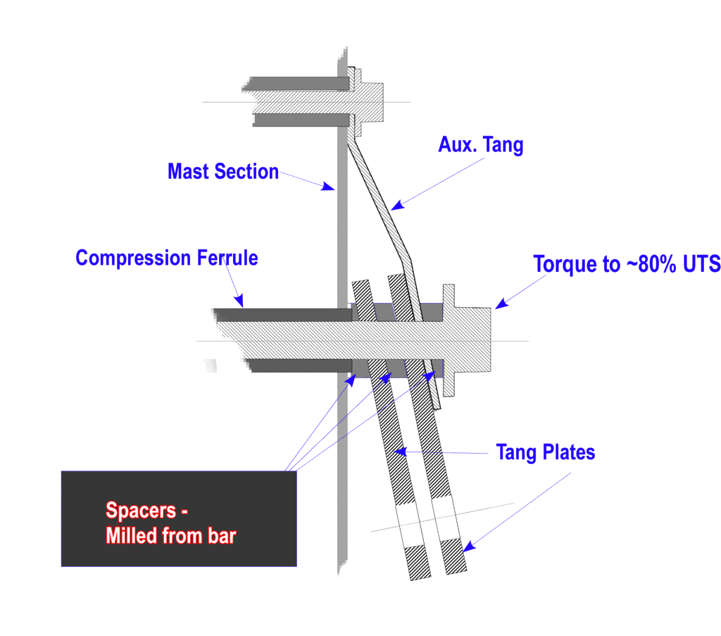
Since the chainplates parts are on their way and everything has to fit inside the spreader mount and spreader, I think I'll probably do it this way. It will provide that back up and reinforcement against bending Bill and I were talking about yesterday.Repeat of http://forums.sbo.sailboatowners.com/showthread.php?t=125412&highlight=tang..... post #36

Oh, yes. There will be a compression tube.
- Status
- Not open for further replies.