I’m installing a new Victron Multiplus 12/2000-80 120v inverter/charger and a Blue Sea custom AC panel. The system is still on the bench, so I am confident it is wired per the diagrams below.
When running on shore power (i.e. plugged into the wall), everything is normal. When I unplug from shore power and the system is delivering AC from the inverter, I was getting a reverse polarity signal on the shore power ELCI, I investigated and found about 60 volts between ground and neutral.
The trouble wasn't apparent until I hooked up the first inverter-supported outlet through the new AC panel. I previously ran test loads directly off the inverter. I've double and triple checked everything from the shore power grounding and polarity to the outlets themselves. I contacted Blue Sea, thinking the ELCI was faulty, but I've since taken the entire panel out of the circuit. I disabled AES on the Multiplus and have been testing the output of the inverter directly.
I tried changing the ground relay setting on the Multiplus. It should be enabled, so that the inverter connects neutral to ground in the absence of shore power. I get 60 volts between neutral and ground with it enabled, and 40 v with it disabled. This is concerning - it should be zero if the ground relay is functioning. Shouldn’t it?
The AC wiring diagram is here:
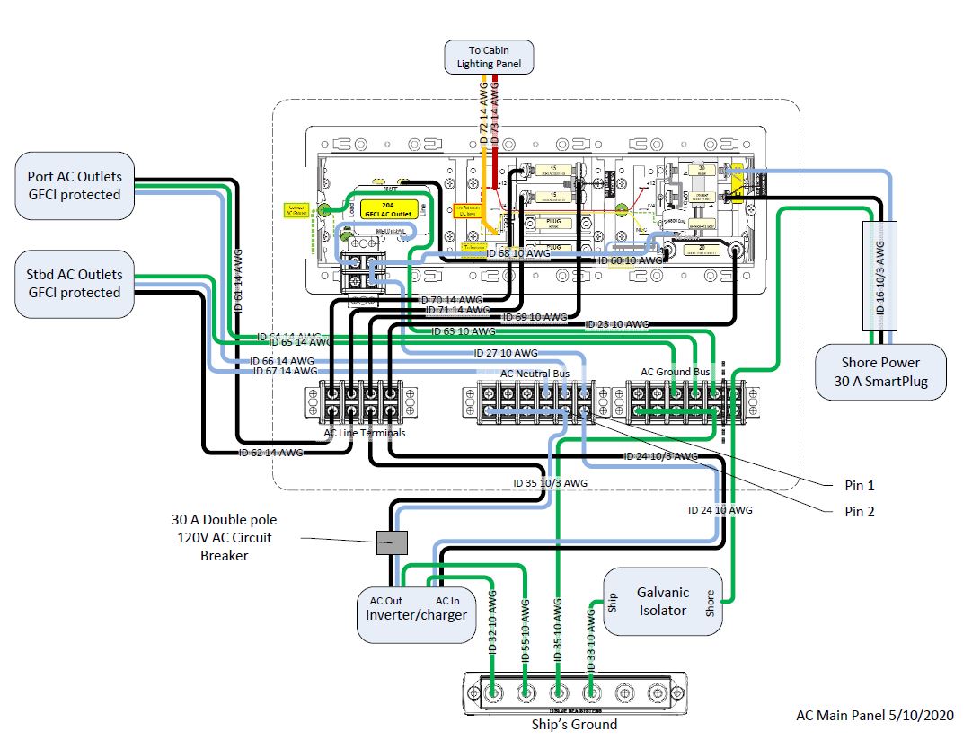
To resolve the issue, I connected all neutrals together. In the diagram, pins 1 and 2 have been jumpered. However, this appears to be incorrect according to ABYC E-31 Figure 4 (Typical inverter/Charger with Internal Transfer to a Split Bus System).
To clarify the wiring diagram:
The 20A GCFI in the AC panel is only connected to shore power. I'm having no issues with this outlet.
Cable ID 23 runs from the ELCI output to the inverter AC input, via the AC Line Terminal. Cable ID 24 supplies AC power to the inverter/charger.
Ground from shore power runs to the galvanic isolator. All grounds are downstream of the GI.
The neutral in Cable ID 35 feeds all inverter neutrals from the inverter/charger. The ground in Cable ID 35 feeds all AC grounds from ship’s ground.
Cable ID 35 connects the inverter/charger to the AC Line Terminals. ID 69 feeds the 2 inverter-supported AC circuits in the AC Panel from the AC Line Terminals.
I’m missing something here, but can’t figure out what is. The neutral should be split, but it doesn’t work that way.
When running on shore power (i.e. plugged into the wall), everything is normal. When I unplug from shore power and the system is delivering AC from the inverter, I was getting a reverse polarity signal on the shore power ELCI, I investigated and found about 60 volts between ground and neutral.
The trouble wasn't apparent until I hooked up the first inverter-supported outlet through the new AC panel. I previously ran test loads directly off the inverter. I've double and triple checked everything from the shore power grounding and polarity to the outlets themselves. I contacted Blue Sea, thinking the ELCI was faulty, but I've since taken the entire panel out of the circuit. I disabled AES on the Multiplus and have been testing the output of the inverter directly.
I tried changing the ground relay setting on the Multiplus. It should be enabled, so that the inverter connects neutral to ground in the absence of shore power. I get 60 volts between neutral and ground with it enabled, and 40 v with it disabled. This is concerning - it should be zero if the ground relay is functioning. Shouldn’t it?
The AC wiring diagram is here:
To resolve the issue, I connected all neutrals together. In the diagram, pins 1 and 2 have been jumpered. However, this appears to be incorrect according to ABYC E-31 Figure 4 (Typical inverter/Charger with Internal Transfer to a Split Bus System).
To clarify the wiring diagram:
The 20A GCFI in the AC panel is only connected to shore power. I'm having no issues with this outlet.
Cable ID 23 runs from the ELCI output to the inverter AC input, via the AC Line Terminal. Cable ID 24 supplies AC power to the inverter/charger.
Ground from shore power runs to the galvanic isolator. All grounds are downstream of the GI.
The neutral in Cable ID 35 feeds all inverter neutrals from the inverter/charger. The ground in Cable ID 35 feeds all AC grounds from ship’s ground.
Cable ID 35 connects the inverter/charger to the AC Line Terminals. ID 69 feeds the 2 inverter-supported AC circuits in the AC Panel from the AC Line Terminals.
I’m missing something here, but can’t figure out what is. The neutral should be split, but it doesn’t work that way.
