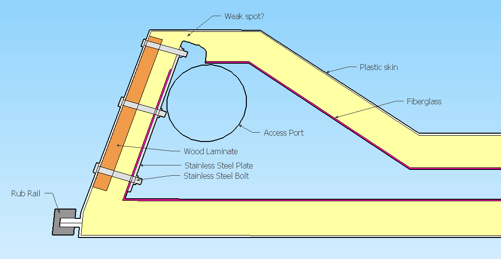
Over the last three years, I have been trying to repair the rudder mount on my 170. I have followed several solutions in this form and other sources to resolve this issue. These solutions have failed to keep the rudder bracket firmly on to the rudder mount when the winds are moderate to high. The last time the rudder bracket pulled away from the rudder mount, I noticed there was a tremendous amount of flex in the back plate of the rudder bracket. Since the tabs on the rudder bracket are of two different lengths, the top mounting screws take most of the force because the flex in the rudder bracket. After thinking about the problem, I believed that the problem does not lie with the rudder mount but with the rudder bracket. During the winter I spent quite a bit of time talking about the rudder bracket with my sailing buddies and I bounced a few ideas on how to eliminate the flex in the rudder bracket. I believe the rudder bracket is made of 1/8th inch stainless steel and thought that doubling the thickness of the back plate of the rudder bracket would eliminate or significantly reduce the flex in the rudder bracket. I took the rudder bracket to a welder who specialized in stainless steel welding and asked him to add another 1/8th inch stainless steel plate onto the back plate of the rudder bracket. I asked him to be sure to weld around the circumference of the bracket to ensure that the additional plate would be firmly attached to the back plate of the rudder bracket.
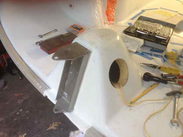
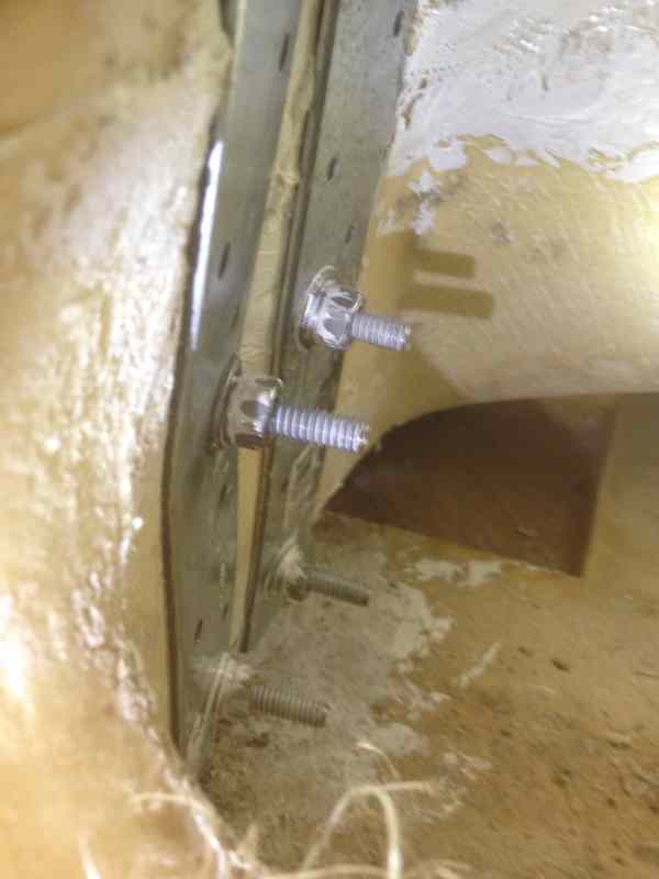
On my vacation in August, I installed the modified rudder bracket to my 170. I filled the old screw holes in the rudder mount with epoxy and added four more screw holes in the rudder bracket giving the bracket 10 screws to hold the bracket to the mount. (This might be more screws than I needed but after the wear and tear on the rudder mount screw holes from the flexing of the rudder bracket, I wanted to be sure that the rudder bracket did not fail because of this wear and tear.) We got 14 sails on the lake in August with three or four with the winds in the moderate to high range. My preliminary assessment of the modified rudder bracket appears to be a complete success. I felt the rudder to be firm with no flexing. A much more positive feel in the tiller which I haven’t seen in the past three years.
Although I am not an engineer and this solution appears to be common sense, I hope that this solution to this problem will work on your 170. I would be interested in finding out the successes in applying this solution to the rudder mount problem.
Best regards
Mike