Man I love building antennas. So what do I have here? I have built a dual band VHF/UHF antenna. Both antennas are tuned to the Amateur Radio bands. However, the VHF antenna can be used on the marine VHF band. So what have I got here?
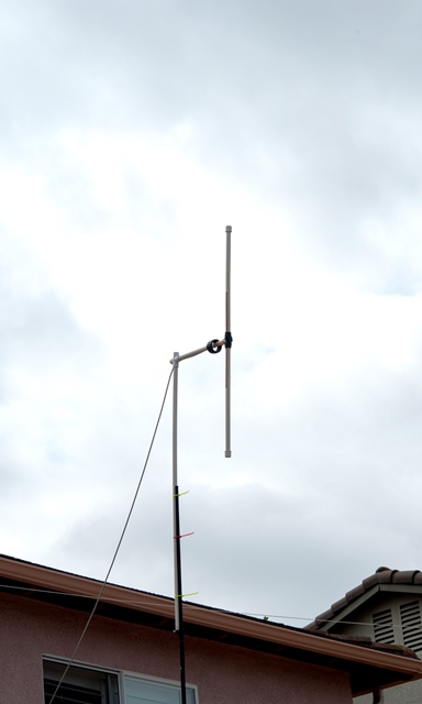
This is the antenna from a distance... Nothing special, just PVC and copper tape. I'll explain the design criteria in the next photos. The mount is temporary because I need to play with the antenna. The mount, by the way, is an old photo light stand.
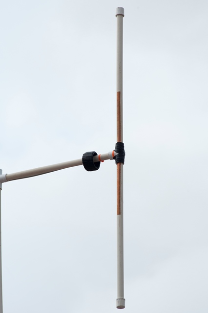
This image is the UHF side of the antenna. It is too long and probably tunes nicely to 220MHz. But it also tunes perfectly for 440MHz. The SWR is low and power is transferred nicely. You can see the copper strip I used. The center of the dipole is taped with amalgamated electrical tape. This tape stretches and binds to itself. The large black tube is actually a common mode choke. I'll explain in the next image.
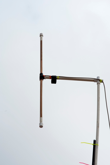
Here is the 2 meter side. 2 meters is 144MHz and is very close to the marine VHF band, just 10MHz away. So this antenna CAN be used on marine VHF band. The design specifics are important to ensure there will be no issues when transmitting. As mentioned, the black tube is a common mode choke. This is nothing more than wrapping the coax around a 2" form about 6 times then taping to keep the form. A common mode choke prevents RF from leaking from the feed point back to the source. You will know if you have an issue with common mode when you transmit and you get shocked, and worst, your electronics on the boat will start to go haywire. Also, you will see the horizontal support, which is 1/4λ (one-quarter wavelength = 19 inches). This is also an electrical requirement to keep the feedpoint impedance near 50Ω.
Use on marine VHF band is as simple as reducing the total length of each copper strip by (maybe) 1.5". There is no marine use on 440MHz, except EPIRB. So that side can be tuned to those frequencies in needed. That's it. So what does this mean to the boater? One can have a similar design stowed below in the event of a demasting. If the vertical and horizontal parts are attached to a boat hook, maybe the antenna can be hoisted around 15' or so. This will get you some range, but the best part is the antenna is a vertical dipole so it has the same pattern as a mast mounted antenna.
My antenna was tested with a 1w handheld. I was able to hit the Catalina Island repeater 67 miles away. OK, a caveat... My elevation is 245' and the repeater elevation is 1600'. So the delta is around 1300'. But by doing the "horizon" math, the repeater is barely peeking over the horizon. So I am not hitting it all the time. But... 1 watt? That's got to be pretty good.
73's
This is the antenna from a distance... Nothing special, just PVC and copper tape. I'll explain the design criteria in the next photos. The mount is temporary because I need to play with the antenna. The mount, by the way, is an old photo light stand.
This image is the UHF side of the antenna. It is too long and probably tunes nicely to 220MHz. But it also tunes perfectly for 440MHz. The SWR is low and power is transferred nicely. You can see the copper strip I used. The center of the dipole is taped with amalgamated electrical tape. This tape stretches and binds to itself. The large black tube is actually a common mode choke. I'll explain in the next image.
Here is the 2 meter side. 2 meters is 144MHz and is very close to the marine VHF band, just 10MHz away. So this antenna CAN be used on marine VHF band. The design specifics are important to ensure there will be no issues when transmitting. As mentioned, the black tube is a common mode choke. This is nothing more than wrapping the coax around a 2" form about 6 times then taping to keep the form. A common mode choke prevents RF from leaking from the feed point back to the source. You will know if you have an issue with common mode when you transmit and you get shocked, and worst, your electronics on the boat will start to go haywire. Also, you will see the horizontal support, which is 1/4λ (one-quarter wavelength = 19 inches). This is also an electrical requirement to keep the feedpoint impedance near 50Ω.
Use on marine VHF band is as simple as reducing the total length of each copper strip by (maybe) 1.5". There is no marine use on 440MHz, except EPIRB. So that side can be tuned to those frequencies in needed. That's it. So what does this mean to the boater? One can have a similar design stowed below in the event of a demasting. If the vertical and horizontal parts are attached to a boat hook, maybe the antenna can be hoisted around 15' or so. This will get you some range, but the best part is the antenna is a vertical dipole so it has the same pattern as a mast mounted antenna.
My antenna was tested with a 1w handheld. I was able to hit the Catalina Island repeater 67 miles away. OK, a caveat... My elevation is 245' and the repeater elevation is 1600'. So the delta is around 1300'. But by doing the "horizon" math, the repeater is barely peeking over the horizon. So I am not hitting it all the time. But... 1 watt? That's got to be pretty good.
73's
Attachments
-
 43.4 KB Views: 318
