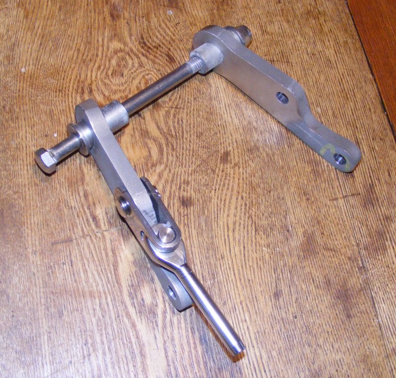
Final Design for Lower Tang Modification

Status
Not open for further replies.
Nov 22, 2008
3,562
Endeavour 32 Portland, Maine
Well, nothing is really final until it's finished but I'm ready to cut parts. Step by step description here:

http://www.facebook.com/album.php?aid=52981&id=1846284215&l=ff058264c1

The existing arrangement turns out not to have a compression tube. Figuring out how to install one without taking everything off the mast to insert one and slide it in half the length of the spar was a challenge. There is 1000 pounds of compression on the mast at this point at maximum rig tension and to that needs to be added the bolt pre-stress to hold the new tang securely.

I like that the tang bears on the S.S. spreader mount which is slightly out from the mast surface so any unusual strain that bends the tang will be isolated from the mast and well spread out by the spreader mount.


Last edited:
Jun 17, 2007
402
MacGregor Mac26S Victoria Tx
Seems like I remember seeing some of your drawings in the past. I don't remember the details though. Was there some problem with the original design? Did it fail prematurely?
 
Nov 22, 2008
3,562
Endeavour 32 Portland, Maine
Was there some problem with the original design? Did it fail prematurely?
Premature failure would be any time I'm on board. :)

There's been a wide difference of opinion here as to whether this is a problem. This shows the upper shroud tangs but the lowers were even worse:

 
Nov 22, 2008
3,562
Endeavour 32 Portland, Maine
So they were 30+ years old and still ok?
Who knows? Stainless is treacherous stuff. It can look fine and pass a dye test for cracks and still come apart at low load. I'm planning to do a lot of hard and long distance sailing to remote areas and I want to start with a zero time rig that I won't be worrying about when I'm ducking brown stuff slinging off the fan blades.
 
Nov 22, 2008
3,562
Endeavour 32 Portland, Maine
Here are the new lower tangs roughed out and trial fit.


After the riggers use them to template the new stay lengths, they will go back for finishing, polishing, and passivating. The bushings will be drilled out for a 1/2" bolt to replace the 3/8" bolt shown here.
 
Last edited:
Jan 27, 2008
3,092
ODay 35 Beaufort, NC
Roger,
Did you do a FEA on the design by any chance? The parts look really nice. Did you end up water jet cutting them or a milling machine?
 
Nov 22, 2008
3,562
Endeavour 32 Portland, Maine
Did you do a FEA on the design by any chance?
No fancy engineering. The thickness is dictated by the cross section at the sides of the hole for the attachment bolt. The outer dimension is restricted by needing to fit inside the existing tubular spreader. Since I'm not going to pay the cost of tapering and shaping to save a few ounces of metal, that leaves me with extra metal in the other portions. Some simple approximations show the worst case stresses even in the asymmetrical aft shroud attachment (longer leg) to be low enough that it's not worth finding out what lies out in the decimal places.

The parts were water jet cut, 50 bucks to cut these and four other parts in two different metal thicknesses. If you can provide a CAD file, it's magic.
 
Jul 1, 2004
567
Hunter 40 St. Petersburg
Can you document this?

Who knows? Stainless is treacherous stuff. It can look fine and pass a dye test for cracks and still come apart at low load.
I just had my 26 year old chainplates dye-tested by the top shop in town and have been given a thumbs up by several prominent riggers for reinstallation after micro-polishing. I've seen failures due to crevice corrosion and other problems often aggravated by water intrusion. Mine are 1" solid stainless rod.
 
Oct 1, 2007
1,865
Boston Whaler Super Sport Pt. Judith
No fancy engineering. The thickness is dictated by the cross section at the sides of the hole for the attachment bolt. The outer dimension is restricted by needing to fit inside the existing tubular spreader. Since I'm not going to pay the cost of tapering and shaping to save a few ounces of metal, that leaves me with extra metal in the other portions. Some simple approximations show the worst case stresses even in the asymmetrical aft shroud attachment (longer leg) to be low enough that it's not worth finding out what lies out in the decimal places.

The parts were water jet cut, 50 bucks to cut these and four other parts in two different metal thicknesses. If you can provide a CAD file, it's magic.
Hi Roger:
I know I'm late to the game on this but I have been reading the posts as your design matured. My question is have you looked at the bending load on the threaded end of the through bolt? That load appears to be transferred to the bolt in the vicinity of the threads, which would not be the best.
 
Sep 15, 2009
6,244
S2 9.2a Fairhope Al
Rodger i have one thing that is of concern to me.....the edge distance around the mounting bolt hole ....should it be 1 and 1/2 times the diamater of the hole size.... mind you this is just a laymens rule of thumb in my mind but i just had to ask .....

regards

woody
 
Feb 6, 1998
11,760
Canadian Sailcraft 36T Casco Bay, ME
After the riggers use them to template the new stay lengths, they will go back for finishing, polishing, and passivating. The bushings will be drilled out for a 1/2" bolt to replace the 3/8" bolt shown here.
Roger,

Those don't look to bad to polish.For some reason I thought they'd be longer. Let me know it you want me to give it a crack. I also have enough Spotless Stainless to soak those in to passivate after polishing..
 
Nov 22, 2008
3,562
Endeavour 32 Portland, Maine
.the edge distance around the mounting bolt hole ....should it be 1 and 1/2 times the diamater of the hole size....
Yes, based on a thinner standard thickness. Cross sectional area of metal is the same as standard chainplate proportions.
 
Nov 22, 2008
3,562
Endeavour 32 Portland, Maine
That load appears to be transferred to the bolt in the vicinity of the threads, which would not be the best.
That's the old bolt which is being replaced. A vital part of such a design is a custom made bolt so that nothing bears on the threads.
 
Nov 6, 2006
10,220
Hunter 34 Mandeville Louisiana
Really nice looking, Roger.. I think you could lift the boat with that !
 
Nov 22, 2008
3,562
Endeavour 32 Portland, Maine
Those don't look to bad to polish.
Phil had a ScotchBrite disk that fits on a grinder. He hit the very rough tang with it for about 10 seconds and, zing!, 3/4 way to a decent finish on that half. He's going to get the disks in the range of grades and I think they will be very close to ready for final polish in pretty short order. What I was expecting to be hours of work should be less than one.
 
Status
Not open for further replies.