Electric 12v Connector Box?

Feb 21, 2008
418
Hunter 33 Metedeconk River
I repacked my stuffing box and in the process, (by my assistant don't ask how) some wires got disconnected. I don't know if any boats other than a H33 2006 has the same setup. There is a relay, about 2"x2" on the port side about 8 inches above the stuffing box and in front of the blower fan. There are about 4-5 spades coming out of it. The center male I think is for the blower and there are a couple of red and a brown wire right there. The yellow powers the blower but may not be in the correct position. It seems that my fuel gauge also has stopped working and may be powered by this relay(?). I looked at the schematics in my Hunter book but could not find anything related. Can someone post what is plugged where or a little simple diagram? Thanks.
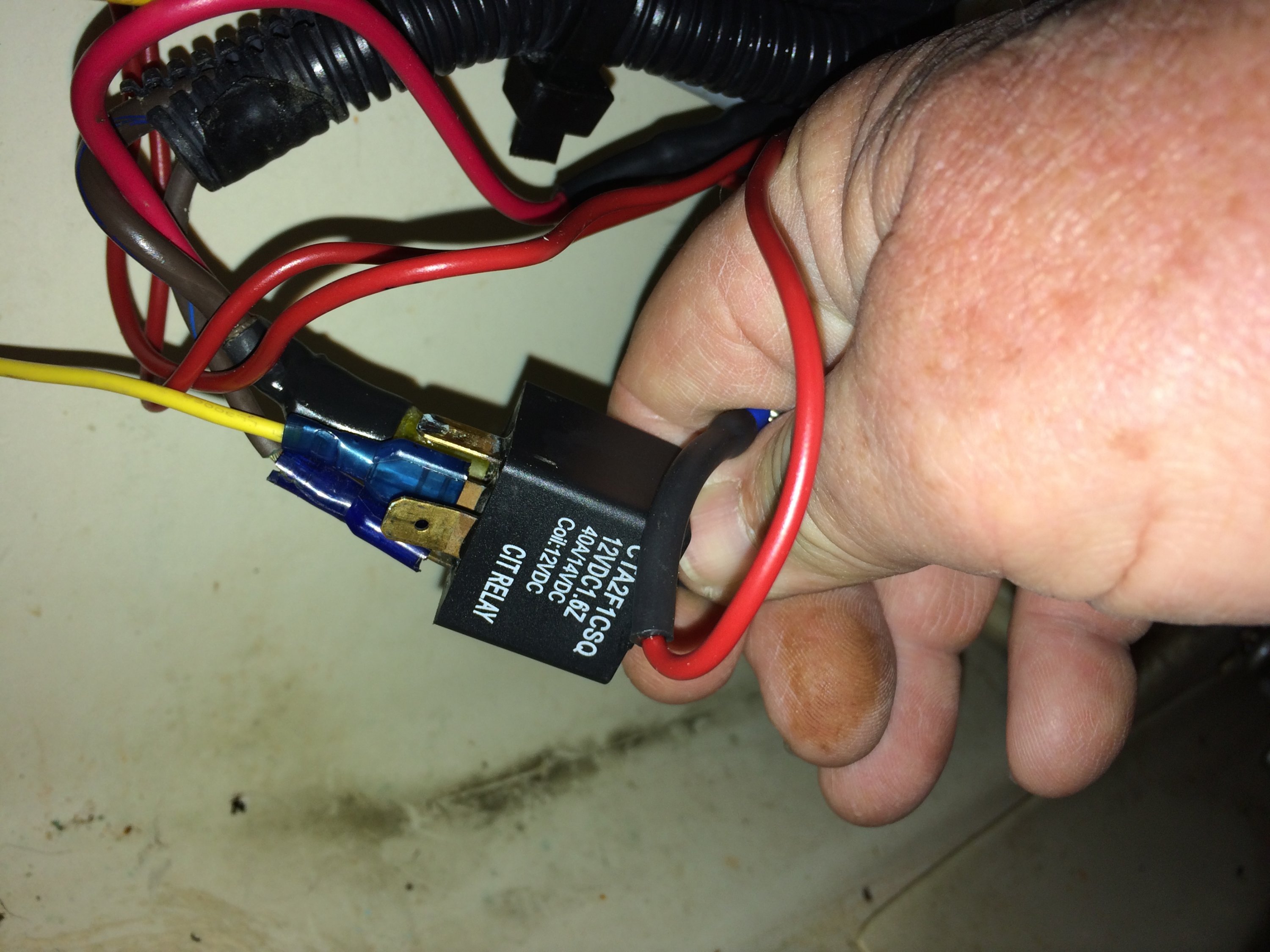
IMG_2862.JPG
 

jssailem

SBO Weather and Forecasting Forum Jim & John
Oct 22, 2014
24,523
CAL 35 Cruiser #21 moored EVERETT WA
Opps.
Time to see what is not working. Maybe have assistant Flip switches. You listen to see is what should start doesn't...:yikes:
 
Jan 4, 2010
1,037
Farr 30 San Francisco
That is not a "connector box" that is a relay. So two of those wires are control wires and cause the relay to actuate. Two of those wires connect to the load. So I would Bing the part number and you will find a complicated data sheet. What is the high current load that stopped working you should be able to trace one of those wires to it.
Where is the switch for that high current load? You should be able to trace some wires to that. Then plug it into the relay in the correct order and tadah!
 
Jan 4, 2010
1,037
Farr 30 San Francisco
Looks like some of those wires are skinny, those should be the relay coil (control) and some of the wires are thick which would be the load
 

jssailem

SBO Weather and Forecasting Forum Jim & John
Oct 22, 2014
24,523
CAL 35 Cruiser #21 moored EVERETT WA
John what you say makes logical sense. Even if the wires are running through conduit, observation is a simple key. As would be choosing some heavy load items to switch on and off. The black wire is likely a ground and the solenoid is likely to have a code stamped near the metal connector. The Code is likely identified in the wire diagram for the boat. Read the code and trace the wires and you can understand the purpose of the solenoid and how it is connected.

But where in the fun in that. Flip switches. It works - it doesn't work. Concrete experience for the physical learner.

JUST BE SURE THAT THE WIRES ARE NOT TOUCHING ANYTHING!:yikes::yikes::yikes: