Charger/ Inverter
- Thread starter gfrazzle
- Start date
Check out this link...
https://forums.sailboatowners.com/i...ing-for-inverter-charger.186747/#post-1391753
Also @Justin_NSA removed his old working Freedom 20, he may want to part with his for $$.
Jim...
https://forums.sailboatowners.com/i...ing-for-inverter-charger.186747/#post-1391753
Also @Justin_NSA removed his old working Freedom 20, he may want to part with his for $$.
Jim...
Yeah, I think you would have to get their own remote. It looks the same size as the Link. If he has a Link that includes an alternator control, that won't work either (altho chances are he doesn't).I'm not sure, if you have a alternator controller or external panel control for your Freedom -- I'd doubt they will work with a Magnum.
I replaced my Freedom with a Magnum 2 years ago. It is so much better! True sine wave which makes a huge difference with wall wart and computer chargers as well as any appliances. It is also a lot more efficient. Had to use the magnum controller but it was not too big a deal as I could use old wires to pull new ones. Definitely recommend.
I replaced my Freedom with a Magnum 2 years ago. It is so much better! True sine wave which makes a huge difference with wall wart and computer chargers as well as any appliances. It is also a lot more efficient. Had to use the magnum controller but it was not too big a deal as I could use old wires to pull new ones. Definitely recommend.
The true sine wave units on standby use a lot more power than the old simulated sine wave Heart (and succeeding Xantrex) units. We never had an issue with computers, TV's, microwaves, or chargers for battery powered tools.
How are the new Magnum units "a lot more efficient"?
The true sine wave units on standby use a lot more power than the old simulated sine wave Heart (and succeeding Xantrex) units. We never had an issue with computers, TV's, microwaves, or chargers for battery powered tools.
How are the new Magnum units "a lot more efficient"?
My experience is in stand by it uses less power. somewhere around an amp but I'd have to look next time I'm on the boat. My xantrex was more like 2.5 amps in standby. I never had issues with chargers but I noticed they would get hot with the modified sine wave, they do not with the magnum. The appliances such as microwave heat items faster with the pure sine wave. Just my experience.
I still have it. Make me an offer if you want it. It comes with the internal inverter, cables, fuse and fuse holder, and remote panel. The beast weighs about 50 lbs so shipping isn't cheap.Check out this link...
https://forums.sailboatowners.com/i...ing-for-inverter-charger.186747/#post-1391753
Also @Justin_NSA removed his old working Freedom 20, he may want to part with his for $$.
Jim...
My experience is in stand by it uses less power. somewhere around an amp but I'd have to look next time I'm on the boat. My xantrex was more like 2.5 amps in standby. I never had issues with chargers but I noticed they would get hot with the modified sine wave, they do not with the magnum. The appliances such as microwave heat items faster with the pure sine wave. Just my experience.
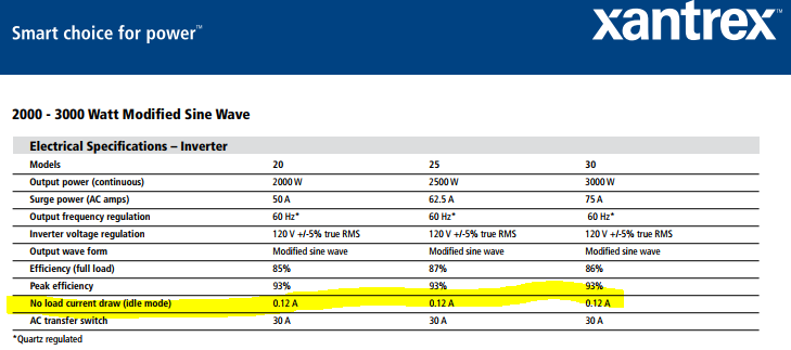
The Heart or Xantrex inverters that are simulated (as opposed to "True" sine wave) had a standy power consumption of 0.12 amps/hour, or so. The true sine inverters are 1.5 amps/hour, or more.
The efficiency factor under load may be about the same between the simulated and true sine inverters -- its different with a higher motor or resistance heating load, than a smaller and more even load.
http://www.xantrex.com/documents/Discontinued-Products/DataSheet/DS20080725_Freedom Marine.pdf
Last edited:
Ok, I'm going to weigh in here.
The standby current isn't the issue you should be concerned about;
It's more important to consider reliability and customer service.
I've called Magnum a few times with questions on my 2812.
Always get through quickly, and their staff are extremely professional.
When I had my xantrex freedom, service was horrible. It was always a "call-back" situation, and when they did call you, you weren't on the boat
Modified sine versus pure sine.
There is no justification for modified sine wave inverters any more. The whole "pure sine" versus "modified sine" started of purely as marketing wank between Xantrex and its competitors
A modified sine wave unit uses high power mosfets to output a series of voltage steps which is smoothed out by huge electrolytic capacitors.
A pure sine inverter also uses mosfet output stages, but they are run in Linear amplification mode.
Years ago the pure sine units had a higher manufacturing cost, owing to costlier processors, and other various silicon.
The main component cost in both units is the magnetics (massive transformer), output mosfets, heat sinks.
There is currently very little BOM cost differential now between MSW and PSW. It's just a way to push a discounted product.
Now, MSW does not play well with items such as microwave ovens. As well, auto-ranging power supplies (wall warts) will get hotter with a MSW vs. PSW.
Conclusion:
Get the magnum PSW unit. It is a "fit & forget" install.
I haven't done any design work on power supply circuits in a few years now, so I may be out of date with my info, but the way that things used to work was like this -
True sign wave was basically an audio amplifier circuit that was fed a sign wave an input signal. The power output was real clean, but the output thyristors ran very hot & this caused a fair amount of power loss.
The approximated sign wave units were usually based on pulse width modulated square waves that were then filtered to become pretty close to being an actual sign wave. If the quality of the filtering was good & the circuit was not overloaded, then the output was usually sort of clean. One of the big upsides to this was the fact that the output thyristors were almost always full on or full off, due to the square waves going through them. This made them run MUCH cooler, with a lot less loss. If you ran your carrier frequency up high enough, then you could run a very small iron core in your inductors & still not run into a problem with flux saturation. Your "transformer" could normally be reduced in size & weight by a factor of 10 or more.
As for the output thyristors, I didn't see that many mosfet's in the stuff I fooled with. Mostly, I saw IGBT's or SCR's in the switchers. Often, I would see discrete silicone transistors in a cascading push pull arrangement in the true sign units. Usually the second stage would be something like a Tip32 & the final stage would be something really chunky, usually in a T-03 case. Most of the fet's I ran into were in true audio circuits. They give a warm tube-like sound, which seems to still be preferred by musicians.
If things are different now, please feel free to fill me in.
Last edited: