
C22 New Style "Stormwatch" Purchase and Refit
- Thread starter Leeward Rail
- Start date
These are really good ideas and your work is looking good. You boat is considerable different than my "original" 1972 model. It is a very nice boat. thanks for showing it and your mods. James
ps. I'm confused is it Ray or Roy?
Thanks James.
It's Roy.. like Roy Rogers
")
But over the years I've got to the point where I usually don't bother correcting more than once when they call me Ray.
As they say.. just don't call me late for dinner.
Regarding that long panel on the starboard side, with the speakers in it ... Mine was (is) rather deteriorated along its lower edge. Not quite bad enough to replace, but I did remove it, cut about 1/8" off the bottom, and Cetol the snot out of it.
You probably already figured this out, but the issue is that water always collects along the bottom inside edge of that locker, out of sight and out of mind, so it stays there and rots that panel. Even if you're aware it's there, it's a pain to get out. But half a dozen or so holes, drilled along the lowest corner, fixes the problem. The water then just drains harmlessly into the bilge.
You probably already figured this out, but the issue is that water always collects along the bottom inside edge of that locker, out of sight and out of mind, so it stays there and rots that panel. Even if you're aware it's there, it's a pain to get out. But half a dozen or so holes, drilled along the lowest corner, fixes the problem. The water then just drains harmlessly into the bilge.
Thanks Gene !half a dozen or so holes, drilled along the lowest corner, fixes the problem. The water then just drains harmlessly into the bilge.
You know, when I took it out I thought to myself that I should improve the drainage, but in my rush to get this thing on the water I promptly forgot about it.
Not sure if I would have done it before I reinstalled the panel. It would have been a "hmm.. ugh.. I forgot to do that" moment in a couple years. Note added to my to do list so I don't forget.
Bulkhead Replacement and Modifications: ... Continued
Here's a quick update on the bulkheads...
As I mentioned before, I couldn't find teak plywood locally, so used cherry veneered plywood instead.
The problem with that is that I wanted it to match the colour of the original teak.
Custom tinting stain is an art. It's much harder to do than matching paint colours.
So, I made a call to a knowledgeable paint store owner I have dealt with before,and learned that the local Sherwin Williams store, that catered to professionals, was the best place to get some stain custom tinted to match.
It took the staff just over 3 hours to match the colour yet for a quart of stain they charged me $25, colour matching included !
Here's a shot of 2 of the 4 bulkheads with the stain applied:
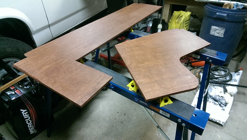
Stained Bulkheads
Once the stain was fully dry, I installed the original bullnose edging onto the new panels.
The starboard bulkhead is the same shape as the original, so I simply reattached it's original bullnose.
For modified port bulkhead, I was able to re-purpose all the original pieces, similar to what "Bilbo" did on his boat "Seadog". In my case I made the bullnose go all the way to the top.
To attach them I put a small bead of weldbond glue on the inside, and secured them with cabinet staples from an air nailer, like the factory did.
I didn't want to attach them too strongly since someone may want to remove them again in the future. I figured that the factory method lasted 30 years and I still needed to remove them with a hammer and wood block.
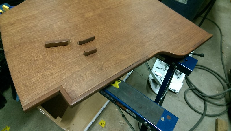
Modified Port Bulkhead with Edging Made From Original Pieces
Comparison of the Modified Port Bulkhead with Original.
(Hopefully you can see how the original edging was reused)
Here's a quick update on the bulkheads...
As I mentioned before, I couldn't find teak plywood locally, so used cherry veneered plywood instead.
The problem with that is that I wanted it to match the colour of the original teak.
Custom tinting stain is an art. It's much harder to do than matching paint colours.
So, I made a call to a knowledgeable paint store owner I have dealt with before,and learned that the local Sherwin Williams store, that catered to professionals, was the best place to get some stain custom tinted to match.
It took the staff just over 3 hours to match the colour yet for a quart of stain they charged me $25, colour matching included !
Here's a shot of 2 of the 4 bulkheads with the stain applied:
Stained Bulkheads
Once the stain was fully dry, I installed the original bullnose edging onto the new panels.
The starboard bulkhead is the same shape as the original, so I simply reattached it's original bullnose.
For modified port bulkhead, I was able to re-purpose all the original pieces, similar to what "Bilbo" did on his boat "Seadog". In my case I made the bullnose go all the way to the top.
To attach them I put a small bead of weldbond glue on the inside, and secured them with cabinet staples from an air nailer, like the factory did.
I didn't want to attach them too strongly since someone may want to remove them again in the future. I figured that the factory method lasted 30 years and I still needed to remove them with a hammer and wood block.
Modified Port Bulkhead with Edging Made From Original Pieces
Comparison of the Modified Port Bulkhead with Original.
(Hopefully you can see how the original edging was reused)
Last edited:
Bulkhead Replacement and Modifications: ... Continued
Alright, I've got a few spare minutes so here's a few updates.
I've now got the bulkheads installed.
Before I installed the bulkheads, I potted the chainplate holes in the deck.
(see next post for details)
I used the original bulkheads to mark and drill JUST the bottom hole for the chainplates.
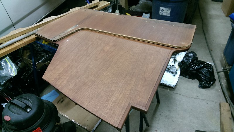
I also coated the edges of the bulkheads with thin epoxy to help prevent future water damage.
Bulkhead with Bottom Chainplate hole drilled, and Epoxy on edges
I then marked and drilled the holes in the bulkhead to bolt them to the fibreglass along the bottom.
You can't get a drill inside the fibreglass area easily, so I just had my wife hold the bulkheads in the correct position while I spun a drill bit, in the fibreglass holes, with my hand, to mark the holes.
Using those marks, I then used an undersized drill to make hole in the bulkheads. I then used the correct size drill bit, to enlarge the hole from both sides. That way the holes would be nice and clean with no splintering.
I bolted the bottom of the bulkheads in place, using stainless steel self locking nuts instead of the original nut+lockwasher combination.
I'll be checking them later, and if they come loose I'll put some thread locking compound on the threads. It's common for the original bolts to come loose.
Once the bottom of the bulkheads were bolted in, I bolted the chainplates into location with the lower hole I had already drilled. I then used the chainplate as a guide to drill the other holes.
I didn't have self locking nuts in the correct size for the chainplates, so I used thread locking compound to keep the nuts from coming loose.
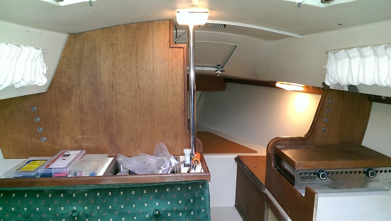
New Bulkheads Mounted in Place
I haven't fully decided what finish to use on the bulkheads.
For that reason I simply sealed the exposed edges with thinned epoxy, and used teak oil like they had from the factory. In the future I may varnish or even epoxy them, but for now I'll be using lemon oil
Next up: The Galley Modification
Alright, I've got a few spare minutes so here's a few updates.
I've now got the bulkheads installed.
Before I installed the bulkheads, I potted the chainplate holes in the deck.
(see next post for details)
I used the original bulkheads to mark and drill JUST the bottom hole for the chainplates.
I also coated the edges of the bulkheads with thin epoxy to help prevent future water damage.
Bulkhead with Bottom Chainplate hole drilled, and Epoxy on edges
I then marked and drilled the holes in the bulkhead to bolt them to the fibreglass along the bottom.
You can't get a drill inside the fibreglass area easily, so I just had my wife hold the bulkheads in the correct position while I spun a drill bit, in the fibreglass holes, with my hand, to mark the holes.
Using those marks, I then used an undersized drill to make hole in the bulkheads. I then used the correct size drill bit, to enlarge the hole from both sides. That way the holes would be nice and clean with no splintering.
I bolted the bottom of the bulkheads in place, using stainless steel self locking nuts instead of the original nut+lockwasher combination.
I'll be checking them later, and if they come loose I'll put some thread locking compound on the threads. It's common for the original bolts to come loose.
Once the bottom of the bulkheads were bolted in, I bolted the chainplates into location with the lower hole I had already drilled. I then used the chainplate as a guide to drill the other holes.
I didn't have self locking nuts in the correct size for the chainplates, so I used thread locking compound to keep the nuts from coming loose.
New Bulkheads Mounted in Place
I haven't fully decided what finish to use on the bulkheads.
For that reason I simply sealed the exposed edges with thinned epoxy, and used teak oil like they had from the factory. In the future I may varnish or even epoxy them, but for now I'll be using lemon oil
Next up: The Galley Modification
Last edited:
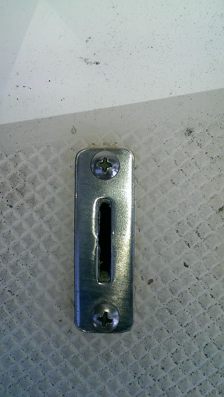
Potting and Rebedding the Upper Shroud Chainplates on a New Style C22:
Before I reinstalled the Bulkheads I needed to "pot" the holes where the chainplates go through the deck.
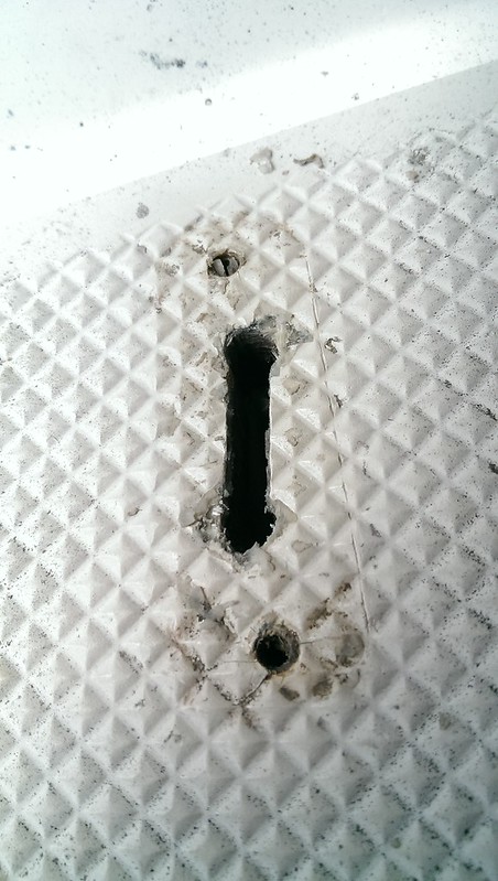
Chainplate Deck Slots
The chainplates are not welded to the flange/plate that screws to the deck.
they simply slide into the slot in the deck plate and the deck.
The whole configuration relies JUST on the the sealant used, to prevent water from getting down into the deck and further down to the bulkheads.
The problem is, like anything else on a sailboat, the chainplates will move, and eventually the sealant will fail.
If you don't regularly inspect the chainplates for leaking, the deck has an unprotected wood core which can rot, and your bulkheads will also get water damaged.
To help reduce the risk of serious damage I "potted" the chainplate slot in the deck, with epoxy. That way, if the sealant ever leaks, the water won't get into the deck core.
The basic idea, is you want to line the holes in the deck with epoxy, so that the wood core is sealed up.
There are 2 ways to do this:
You can either make the slot and holes oversized so you can fill them with epoxy, and redrill the holes to toe correct smaller size.
Or you can use a rotary tool or drill to cut away some of the deck core, leaving the outer fibreglass untouched, and then fill the hole with epoxy and redrill it.
For these chainplates I used both methods. One for the screw holes, the other for the chainplate slot itself.
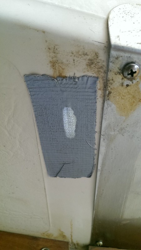
The first thing I did was to put duct tape on the bottom of the chainplate slot inside the hull.
This way I can fill the slot with epoxy without it simply draining into the cabin.
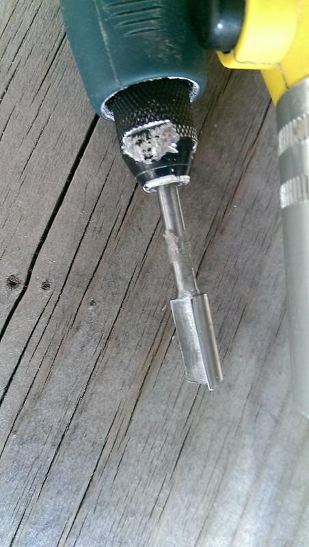
Next task, was to drill the screw holes larger than they are originally.
Since the screw holes don't go all the way through the deck, I measured the depth of the hole, and put some tape on the drill bit at that length, so would only drill that deep.
There are adjustable depth stops made for drill bits. I lost mine and haven't replaced it because the tape method works well enough for the few times I need it.
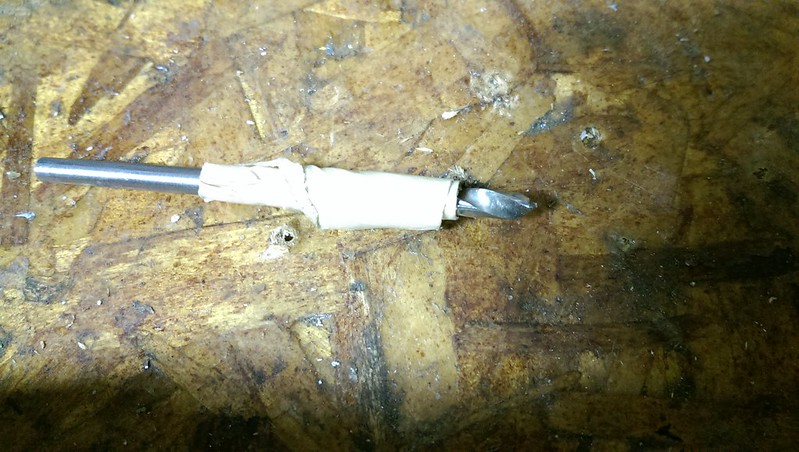
Drill bit with tape used as a depth gauge.
Once the screw holes were drilled larger in diameter, I had used a Dremel #654 bit, to remove the deck core around the chainplate slot.
Some people do this with a bent nail or other means. I have a no-name dremel style rotary tool with a flex shaft so I use that.
The slot itself was a bit smaller than the dremel bit, but the ends of the slot were big enough for the bit to fit.
I simply inserted the bit into the hole, deep enough so that I was cutting only the core, and not the outer fibreglass layers.
Buy using the thin, smooth, shaft section of the router bit, against the outer fibreglass layer, as a guide, I cut away a layer of wood core from around the hole.
Once I had finished cutting the small layer of core away, I used an air gun to blow all the debris out of the hole.
Next I:
a) put tape over/around the holes to protect the deck from excess epoxy.
b) cut away the tape from the holes
c) mixed up some west system epoxy from a repair kit I had (a single packet of epoxy will do more then both chainplates)
d) used a syringe to fill the holes with epoxy
e) waited a few minutes
f) sucked all the epoxy out
g) added west system adhesive filler to thicken the mixture
h) used the syringe to fill the holes with the now thickened epoxy
I) waited 24hrs for the epoxy to fully cure. (in warmer weather the epoxy would have cured faster)
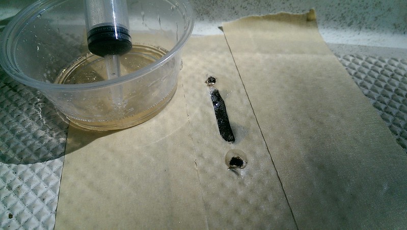
Chainplate holes filled with epoxy.
Once the epoxy had fully cured, I used the a drill bit to drill the screw holes to the ORIGINAL, SMALLER SIZE.
As before, I used tape as a depth gauge on the drill bit, so that I didn't accidentally drill all the way through the deck.
I then temporarily screwed the chainplate cover plates in place.
This way I could use the plates as as a guide to re-cut the chainplate slots.
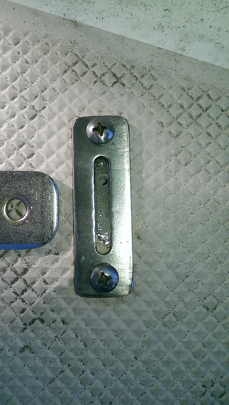
Cover Plate Ready to Be Used As A Guide To Re-cut The Slot.
To drill the slot, I used a drill bit that was the same size as the chainplate thickness.
First I drilled a series of holes side by side...
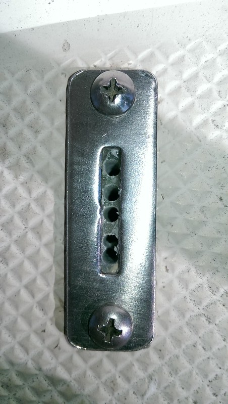
Multiple Holes Drilled Where The Slot Should Be
Once I had a series of holes drilled in the slot, I took the same drill bit and pulled it sideways to cut between each hole and make the finished slot. The plate worked as a guide.
The drill bit is fairly thin so your need to do this fairly gently so you don't brake the drill bit. By doing it gently, you can cut the epoxy without damaging the hard stainless steel plate.
The original slots were larger than the slot on the plate. Since I was using the slot as a guide, the gap around the chainplate was smaller with less chance of a leak. There was just enough of a gap to allow good adhesion for butyl tape or sealant.
I should note here... I was using safety glasses the whole project, so I didn't get bits of debris in my eyes. Trust me... USE THEM... I've been to the hospital twice over the years, getting debris removed. The second time I had even been using safety glasses and still got stuff embedded near my cornea ! Go blind and your sailing days are over.
Chainplate Slot Complete
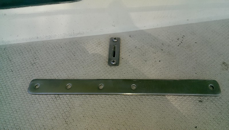
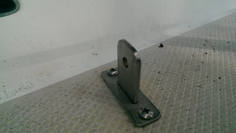
Test Fitting The Chainplate Before Bulkhead Re-installation
Once the bulkheads were fully re-installed and the chainplates bolted in, I used Butyl Tape to bed the chainplate deck plate so that water couldn't get in. Before I bedded them, I used a countersink bit to slighty countersink the top of the screw holes. That way the sealant or butyl tape had something more to adhere to.
Before I reinstalled the Bulkheads I needed to "pot" the holes where the chainplates go through the deck.
Chainplate Deck Slots
The chainplates are not welded to the flange/plate that screws to the deck.
they simply slide into the slot in the deck plate and the deck.
The whole configuration relies JUST on the the sealant used, to prevent water from getting down into the deck and further down to the bulkheads.
The problem is, like anything else on a sailboat, the chainplates will move, and eventually the sealant will fail.
If you don't regularly inspect the chainplates for leaking, the deck has an unprotected wood core which can rot, and your bulkheads will also get water damaged.
To help reduce the risk of serious damage I "potted" the chainplate slot in the deck, with epoxy. That way, if the sealant ever leaks, the water won't get into the deck core.
The basic idea, is you want to line the holes in the deck with epoxy, so that the wood core is sealed up.
There are 2 ways to do this:
You can either make the slot and holes oversized so you can fill them with epoxy, and redrill the holes to toe correct smaller size.
Or you can use a rotary tool or drill to cut away some of the deck core, leaving the outer fibreglass untouched, and then fill the hole with epoxy and redrill it.
For these chainplates I used both methods. One for the screw holes, the other for the chainplate slot itself.
The first thing I did was to put duct tape on the bottom of the chainplate slot inside the hull.
This way I can fill the slot with epoxy without it simply draining into the cabin.
Next task, was to drill the screw holes larger than they are originally.
Since the screw holes don't go all the way through the deck, I measured the depth of the hole, and put some tape on the drill bit at that length, so would only drill that deep.
There are adjustable depth stops made for drill bits. I lost mine and haven't replaced it because the tape method works well enough for the few times I need it.
Drill bit with tape used as a depth gauge.
Once the screw holes were drilled larger in diameter, I had used a Dremel #654 bit, to remove the deck core around the chainplate slot.
Some people do this with a bent nail or other means. I have a no-name dremel style rotary tool with a flex shaft so I use that.
The slot itself was a bit smaller than the dremel bit, but the ends of the slot were big enough for the bit to fit.
I simply inserted the bit into the hole, deep enough so that I was cutting only the core, and not the outer fibreglass layers.
Buy using the thin, smooth, shaft section of the router bit, against the outer fibreglass layer, as a guide, I cut away a layer of wood core from around the hole.
Once I had finished cutting the small layer of core away, I used an air gun to blow all the debris out of the hole.
Next I:
a) put tape over/around the holes to protect the deck from excess epoxy.
b) cut away the tape from the holes
c) mixed up some west system epoxy from a repair kit I had (a single packet of epoxy will do more then both chainplates)
d) used a syringe to fill the holes with epoxy
e) waited a few minutes
f) sucked all the epoxy out
g) added west system adhesive filler to thicken the mixture
h) used the syringe to fill the holes with the now thickened epoxy
I) waited 24hrs for the epoxy to fully cure. (in warmer weather the epoxy would have cured faster)
Chainplate holes filled with epoxy.
Once the epoxy had fully cured, I used the a drill bit to drill the screw holes to the ORIGINAL, SMALLER SIZE.
As before, I used tape as a depth gauge on the drill bit, so that I didn't accidentally drill all the way through the deck.
I then temporarily screwed the chainplate cover plates in place.
This way I could use the plates as as a guide to re-cut the chainplate slots.
Cover Plate Ready to Be Used As A Guide To Re-cut The Slot.
To drill the slot, I used a drill bit that was the same size as the chainplate thickness.
First I drilled a series of holes side by side...
Multiple Holes Drilled Where The Slot Should Be
Once I had a series of holes drilled in the slot, I took the same drill bit and pulled it sideways to cut between each hole and make the finished slot. The plate worked as a guide.
The drill bit is fairly thin so your need to do this fairly gently so you don't brake the drill bit. By doing it gently, you can cut the epoxy without damaging the hard stainless steel plate.
The original slots were larger than the slot on the plate. Since I was using the slot as a guide, the gap around the chainplate was smaller with less chance of a leak. There was just enough of a gap to allow good adhesion for butyl tape or sealant.
I should note here... I was using safety glasses the whole project, so I didn't get bits of debris in my eyes. Trust me... USE THEM... I've been to the hospital twice over the years, getting debris removed. The second time I had even been using safety glasses and still got stuff embedded near my cornea ! Go blind and your sailing days are over.
Chainplate Slot Complete
Test Fitting The Chainplate Before Bulkhead Re-installation
Once the bulkheads were fully re-installed and the chainplates bolted in, I used Butyl Tape to bed the chainplate deck plate so that water couldn't get in. Before I bedded them, I used a countersink bit to slighty countersink the top of the screw holes. That way the sealant or butyl tape had something more to adhere to.
Last edited:
Galley Modifications:
The modifications I'm making to the galley are an almost direct copy of the design that forum member "Watercolors!" did on his boat 10 years ago.
Jerry was kind enough to send me details on how he did his modification, so I could post it here.
---------
What you get:
As mentioned, the main modification is to turn the stove 90 degrees, shorten the starboard bunk by approximately 8 inches,and install an additional bulkhead.
You get 2 new drawers.
One for plates, bowls, knives, forks and spoons.
One that could hold larger knives, BBQ tongs, BBQ lighter, spatula, etc.
Optionally you can modify the existing drawer.
You get shelves above the stove for things like spices, tea, etc
You get a deep vertical storage spot for 2 stacks of cups.
You not only have a lot more storage... Both burners of the stove are now in the open, instead of one burner being very close to the curtains, and deck.
------------
Here are photos of "Watercolors" original galley modification:
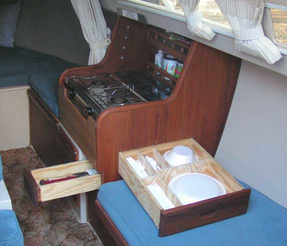
Additional Drawers
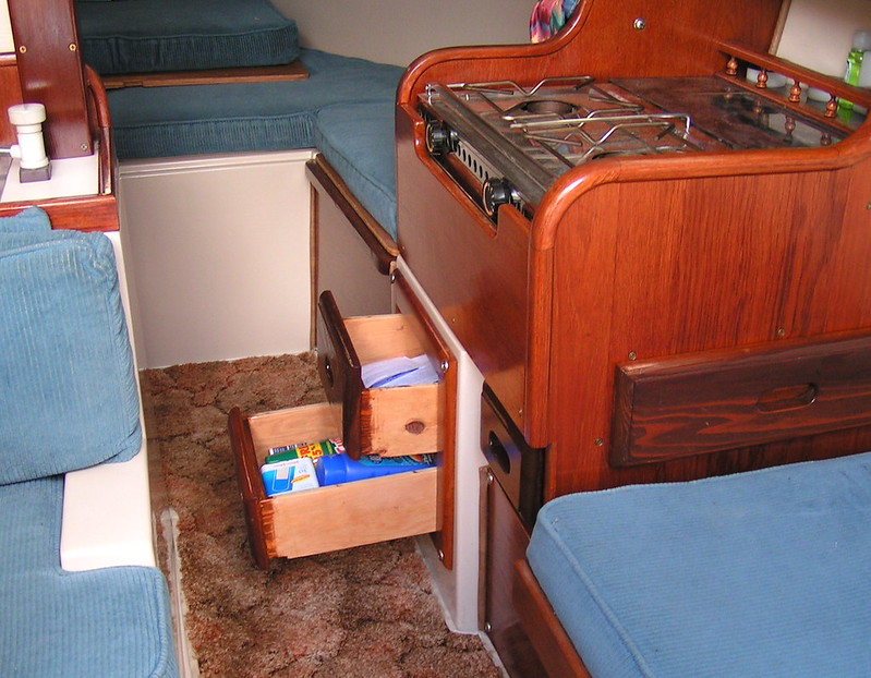
Original Single Deep Drawer Converted to 2 Shallower Drawers
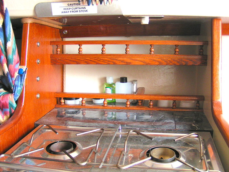
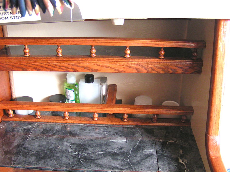
Shelves Behind Stove
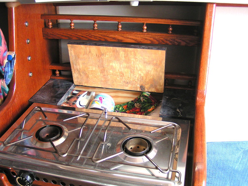
Hidden Storage Below Countertop
Storage for Stacks of Cups on Right Rear Corner
(It's deeper on the right because there is no fibreglass bulkhead below)
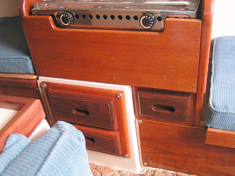
Front Drawer View
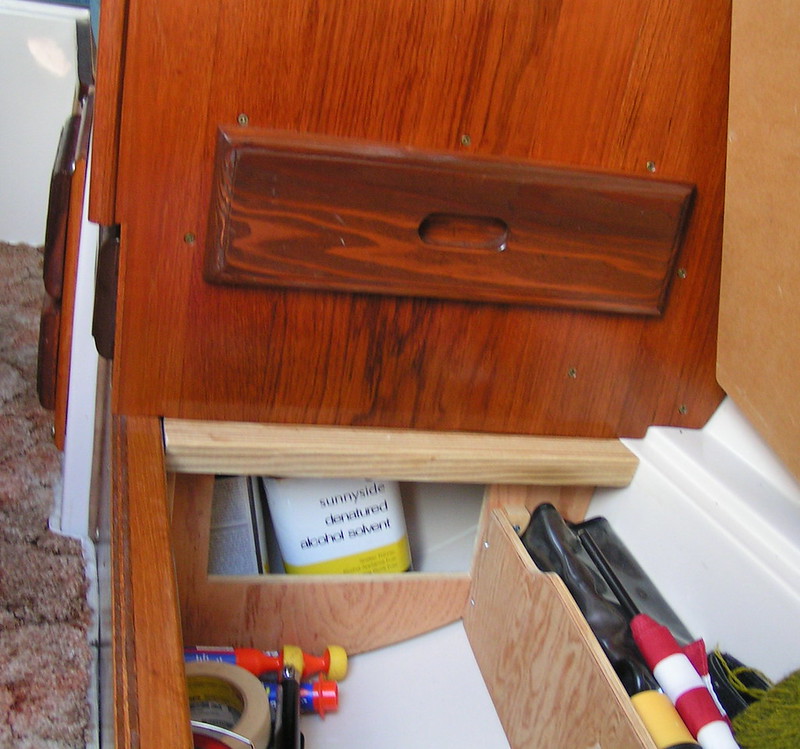
Storage Underneath
The modifications I'm making to the galley are an almost direct copy of the design that forum member "Watercolors!" did on his boat 10 years ago.
Jerry was kind enough to send me details on how he did his modification, so I could post it here.
---------
What you get:
As mentioned, the main modification is to turn the stove 90 degrees, shorten the starboard bunk by approximately 8 inches,and install an additional bulkhead.
You get 2 new drawers.
One for plates, bowls, knives, forks and spoons.
One that could hold larger knives, BBQ tongs, BBQ lighter, spatula, etc.
Optionally you can modify the existing drawer.
You get shelves above the stove for things like spices, tea, etc
You get a deep vertical storage spot for 2 stacks of cups.
You not only have a lot more storage... Both burners of the stove are now in the open, instead of one burner being very close to the curtains, and deck.
------------
Here are photos of "Watercolors" original galley modification:
Additional Drawers
Original Single Deep Drawer Converted to 2 Shallower Drawers
Shelves Behind Stove
Hidden Storage Below Countertop
Storage for Stacks of Cups on Right Rear Corner
(It's deeper on the right because there is no fibreglass bulkhead below)
Front Drawer View
Storage Underneath
Last edited:
Yes, Watercolors does fantastic work. The galley mod is a great design and well executed.That's really beautiful.
James
He used to make custom van interiors years ago.
With luck, my finished project will be almost as good.
Yeah that looks to me like it should have been done that way from the factory. I'll probably get around to doing it myself someday. His shelving on the port side looks great too. Nothing like creating useful space out of thin air!
Sure would be a neat article with photos for the MainBrace.
By the way, the MainBrace will be out next week, and I believe there will be a nice article concerning the "new design" C-22's,(the prettiest girl in the marina!)
Very nice!
Don
By the way, the MainBrace will be out next week, and I believe there will be a nice article concerning the "new design" C-22's,(the prettiest girl in the marina!)
Very nice!
Don
Gene: "Why didn't they do that originally?" I said the same thing to my wife when I saw Jerry's photos for the first time. I'm planning on doing Jerry's portside countertop shelf too. The new full height port bulkhead will have storage too, but I'm not sure what yet. VHF radio may get moved. I'm waiting for some inspiration. I'm looking for a used keyboard drawer for use under the table.
The whole project may not get finished until the fall. It's more about getting the boat usable for now.
James: I'm not going to modify Jerry's design much at all. How the new bulkhead works in combination with starboard storage is already different. The drawer will be different dimensions to accommodate washable plates. I haven't figured out how I'll handle the shelves yet. They may change. I'll be leaving the factory drawer as is for now.
The big concern, is being able to cut into the fibreglass without compromising the strength of the original structure. Jerry came up with a way to do it, that not only simplifies installing the main drawer, but makes things nice and strong.
Don: I agree, once this is all complete it should be a good way to inspire other C22 mods.
Russ: The only real hassle IMO was making the bulkhead templates. For someone with bulkheads in good shape, it would be much easier to do the galley mod.
I wondered about selling bulkheads for that very reason, but I'm not sure they would be reasonably priced.
It does seem like it's a common problem having them rot.
Cheers,
Roy
P.S. Thanks for the compliments, though I think you guys are delusional.
-----
Outboard Motor Mount Board
------
Due to age and neglect the motor mount board on Stormwatch has seen better days.
It was slowly rotting because it hadn't been varnished in a while.
I considered sanding a refinishing it, but decided that, while I like wood trim, I preferred to replace it a low maintenance solid HDPE one.
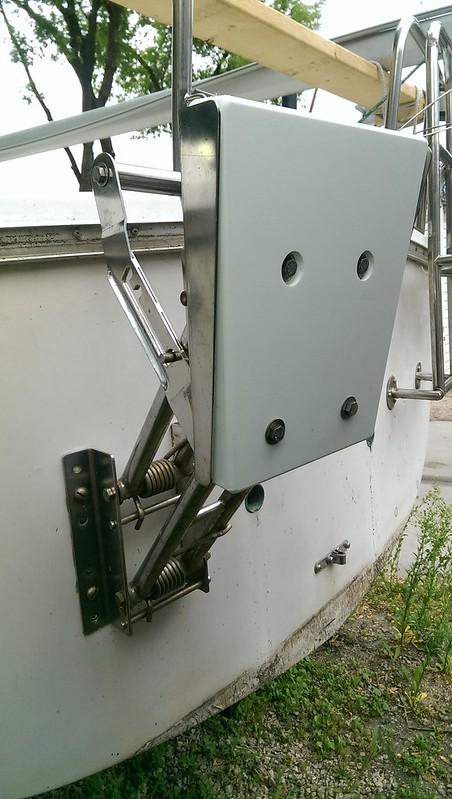
In fact, when I removed it to replace it, I discovered the back of the board, which sat against the stainless steel motor mount support plate, was rotted so bad, I couldn't have refinished it anyhow.
Removing the old board was simply a matter of removing the old bolts, nuts, and fender washers.
A word of warning though.. On my New Style C22, the stainless backing plate on the motor mount was welded in place ONLY at the top edge of the bracket. If you move the plate in and out too much, when trying to loosen the bolts or remove the old board, you could break the weld.
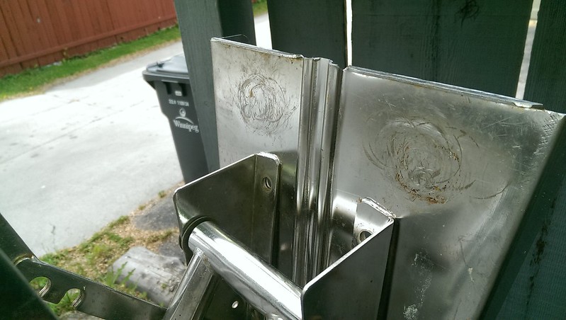
ALSO: Some of the older boats evidently didn't come with a stainless backing plate. If your boat doesn't have one, you should install one before you install the new HDPE mounting board or you run the risk of losing your motor into the sea.
The new plastic motor mount board came without mounting holes. I preferred this since it prevents any problems if the holes are slightly different on my boat.
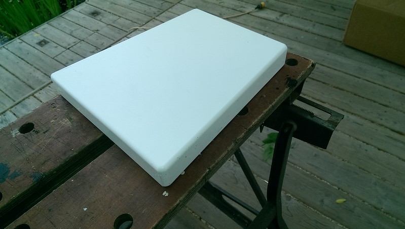
Nice new HDPE Outboard Motor Mount Board
To drill the new holes I simply clamped the old mounting board on top of the new one, then drilled through the old holes in the old board, into the new board.
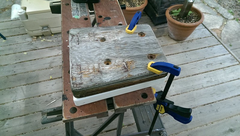
Ready to Drill the Holes using the old holes as a template
You will notice, that the two upper holes on the old motor mount board are recessed.
This is so that the head of the bolt and the fender washers wouldn't protrude above the surface of the board itself, and get in the way of the outboard's mounting clamps.
Once I had drilled all four holes, I recessed the two upper ones by re-drilling each hole, part way into the new motor mount board, with a wood spade bit.
http://en.wikipedia.org/wiki/Drill_bit#Wood_spade_bits
The plastic is soft enough that a spade bit will easily drill through it.
I chose a spade bit that was the same diameter as the fender washers used for the mounting bolts.
I just drilled deep enough, so that the head of the bolt would be just below the surface of the board, when installed.
Once the holes were completed, I installed the new board with NEW STAINLESS STEEL BOLTS, WASHERS, AND LOCK NUTS. You don't want to trust your expensive motor's safety, to some 30 year old bolts !
Outboard Motor Mount Board
------
Due to age and neglect the motor mount board on Stormwatch has seen better days.
It was slowly rotting because it hadn't been varnished in a while.
I considered sanding a refinishing it, but decided that, while I like wood trim, I preferred to replace it a low maintenance solid HDPE one.
In fact, when I removed it to replace it, I discovered the back of the board, which sat against the stainless steel motor mount support plate, was rotted so bad, I couldn't have refinished it anyhow.
Removing the old board was simply a matter of removing the old bolts, nuts, and fender washers.
A word of warning though.. On my New Style C22, the stainless backing plate on the motor mount was welded in place ONLY at the top edge of the bracket. If you move the plate in and out too much, when trying to loosen the bolts or remove the old board, you could break the weld.
ALSO: Some of the older boats evidently didn't come with a stainless backing plate. If your boat doesn't have one, you should install one before you install the new HDPE mounting board or you run the risk of losing your motor into the sea.
The new plastic motor mount board came without mounting holes. I preferred this since it prevents any problems if the holes are slightly different on my boat.
Nice new HDPE Outboard Motor Mount Board
To drill the new holes I simply clamped the old mounting board on top of the new one, then drilled through the old holes in the old board, into the new board.
Ready to Drill the Holes using the old holes as a template
You will notice, that the two upper holes on the old motor mount board are recessed.
This is so that the head of the bolt and the fender washers wouldn't protrude above the surface of the board itself, and get in the way of the outboard's mounting clamps.
Once I had drilled all four holes, I recessed the two upper ones by re-drilling each hole, part way into the new motor mount board, with a wood spade bit.
http://en.wikipedia.org/wiki/Drill_bit#Wood_spade_bits
The plastic is soft enough that a spade bit will easily drill through it.
I chose a spade bit that was the same diameter as the fender washers used for the mounting bolts.
I just drilled deep enough, so that the head of the bolt would be just below the surface of the board, when installed.
Once the holes were completed, I installed the new board with NEW STAINLESS STEEL BOLTS, WASHERS, AND LOCK NUTS. You don't want to trust your expensive motor's safety, to some 30 year old bolts !
Last edited:
-----
Teak Cabin Top Handrails
------
While the boat was in reasonable shape, the teak had been neglected.
While the hatch boards and other parts could simply be refinished, both hand rails had split in 2 locations where the screws attached them to the deck.
I did some shopping around for replacements:
With currency exchange and shipping being what it is I decided to make a few phone calls and see if any of the local wood suppliers had some teak planks I could use to make my own handrails.
I lucked out, and found some teak planks, in the perfect width, height, and length, for $17 each.
The process of making them is easy if you have a router, a jigsaw or scroll saw, some sandpaper.
You could do the whole thing with a hand coping saw and a lot of sanding.
First thing I did was simply clamp the original handrail to the teak plank.
I then used a pencil to trace the outline of the old rail onto the new plank.
Tracing the outline of the rails onto the teak plank
I then used a jigsaw to cut the plank along the traced outline.
(Note: cutting straight, vertically, with a jigsaw is somewhat difficult, and I recommend using a scroll saw instead. The jig saw blade can have a tendency to bend to one side when cutting thicker material + cutting curved shapes. In my case, I had to gently re-trim the edges with the jigsaw because of that problem.)
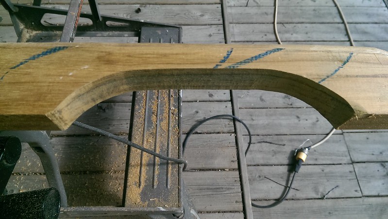
Cut Outline With a Jigsaw
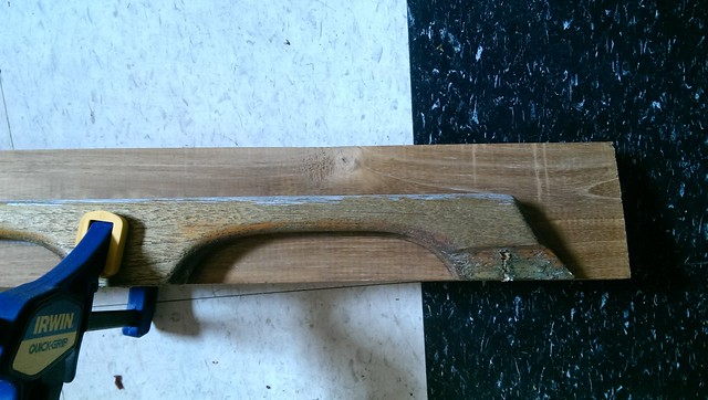
Once the basic shape was completed, I clamped the new rails onto worktable, and used a 1/2" round off bit in a router, to round off (surprise !) the top edge and internal edges of rails.
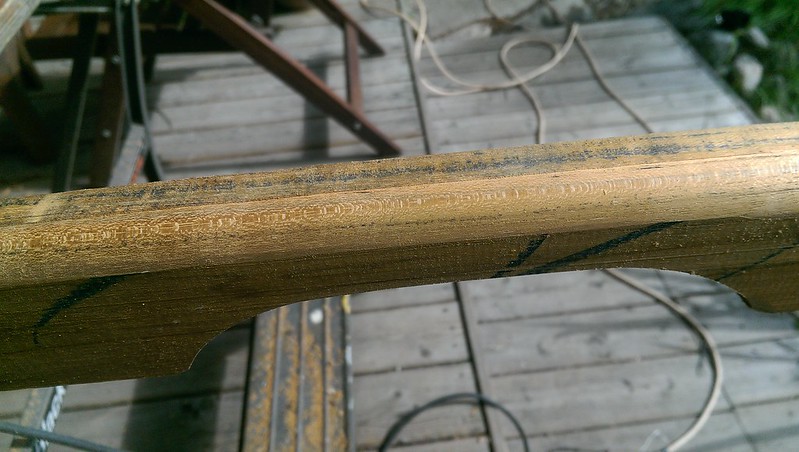
Closeup of top edges after using a router and a 1/2" roundoff bit. Cutout area had yet to be rounded off.
Once I had the edges rounded off with a router, I used 190 and 220 grit sandpaper to smooth the whole rail to the final shape.
(Note: The planks I used where the correct thickness, so all I had to do was smooth the sides. If the planks were thicker, I would have had to cut them to size with a table saw, before I started)
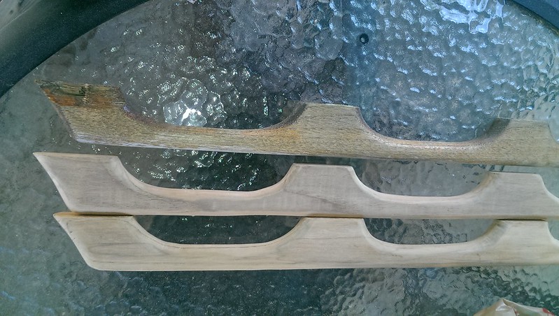
Two New Handrails Beside Original Damaged One.
Update:
While the handrails were removed from the boat, I used some putty temporarily on each hole to prevent rain water from getting inside.
Before I mounted the handrails, I used a dremel, epoxy, and a counter sink bit, to "pot" each hole like I did in previous posts, for other holes in deck. This way the deck core was protected from rot.
I mounted the handrails with the original screws. To help prevent future splitting, I pre-drilled the holes in the handrails, using the original rails as a placement guide.
I used butyl tape at every screw location to prevent leaks.
In the future, I'd like to through-bolt the handrails to the deck, but using screws, like the factory did, gets the boat on the water faster.

Handrail laying on deck in preparation for installation.
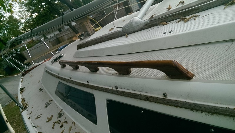
New handrail installed. The other teak will refinished this fall/winter.
Teak Cabin Top Handrails
------
While the boat was in reasonable shape, the teak had been neglected.
While the hatch boards and other parts could simply be refinished, both hand rails had split in 2 locations where the screws attached them to the deck.
I did some shopping around for replacements:
sailboatowners.com sells generic "4 Loop" teak handrails for $35 each.
http://shop.sailboatowners.com/prod.php?8611
Catalina Direct exact fit handrails, for $142 a pair
The generic ones may fit perfectly, but I wasn't willing to take a chance and have to send them back. (or deal with drilling new holes in the deck)http://shop.sailboatowners.com/prod.php?8611
Catalina Direct exact fit handrails, for $142 a pair
With currency exchange and shipping being what it is I decided to make a few phone calls and see if any of the local wood suppliers had some teak planks I could use to make my own handrails.
I lucked out, and found some teak planks, in the perfect width, height, and length, for $17 each.
The process of making them is easy if you have a router, a jigsaw or scroll saw, some sandpaper.
You could do the whole thing with a hand coping saw and a lot of sanding.
First thing I did was simply clamp the original handrail to the teak plank.
I then used a pencil to trace the outline of the old rail onto the new plank.
Tracing the outline of the rails onto the teak plank
I then used a jigsaw to cut the plank along the traced outline.
(Note: cutting straight, vertically, with a jigsaw is somewhat difficult, and I recommend using a scroll saw instead. The jig saw blade can have a tendency to bend to one side when cutting thicker material + cutting curved shapes. In my case, I had to gently re-trim the edges with the jigsaw because of that problem.)
Cut Outline With a Jigsaw
Once the basic shape was completed, I clamped the new rails onto worktable, and used a 1/2" round off bit in a router, to round off (surprise !) the top edge and internal edges of rails.
Closeup of top edges after using a router and a 1/2" roundoff bit. Cutout area had yet to be rounded off.
Once I had the edges rounded off with a router, I used 190 and 220 grit sandpaper to smooth the whole rail to the final shape.
(Note: The planks I used where the correct thickness, so all I had to do was smooth the sides. If the planks were thicker, I would have had to cut them to size with a table saw, before I started)
Two New Handrails Beside Original Damaged One.
Update:
While the handrails were removed from the boat, I used some putty temporarily on each hole to prevent rain water from getting inside.
Before I mounted the handrails, I used a dremel, epoxy, and a counter sink bit, to "pot" each hole like I did in previous posts, for other holes in deck. This way the deck core was protected from rot.
I mounted the handrails with the original screws. To help prevent future splitting, I pre-drilled the holes in the handrails, using the original rails as a placement guide.
I used butyl tape at every screw location to prevent leaks.
In the future, I'd like to through-bolt the handrails to the deck, but using screws, like the factory did, gets the boat on the water faster.
Handrail laying on deck in preparation for installation.
New handrail installed. The other teak will refinished this fall/winter.
Last edited:
------
Switch Panel Modification and Battery Box installation
------
I was told by the previous owners, that the wiring in the boat hadn't been used in the 5 years they owned the boat. They said they only day sailed.
Judging by the boats wiring, they were telling the truth.
There was a CD/Stereo with both power and speaker wires held together only with electrical tape, and a DC/AC Inverter, just sitting on the starboard bunk.
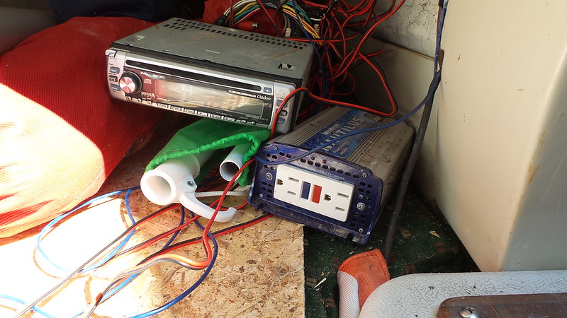
Previous owner's CD/Stereo and Inverter Wiring !
(I'm not sure what the OSB board was for... it came in handy for temporary hatchboards while the real ones are being varnished.)
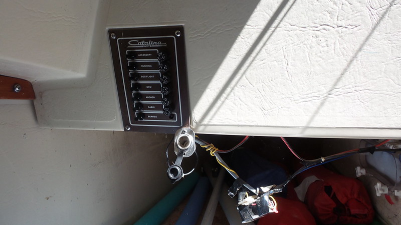
Switch Panel with hanging wiring !
Judging by the fact the shielding for the VHF antenna cable was broken, the old installed VHF radio wasn't used either.
In fact the boat didn't have a battery box, or a battery.
My first task was to check all the wiring in the boat, to ensure that I wouldn't end up with a electrical fire when I installed a battery.
I visually traced and checked all the wiring, and their connections.
I was prepared for the worst, but in fact, the original wiring was in reasonable shape.
It was the badly done add-ons that were a problem.
I decided that I would remove anything that wasn't the basics and get the basic stuff up and running.
Tasks List:
Yank, cut, etc... done.
Next I ripped out the complete CD/Stereo and all it's related wiring.
I don't plan to reinstall it. Who the heck uses CDs more than the single time to copy them to your media library ? What is this 1987 ?
Eventually I'll install a bluetooth connected, 12volt powered, ipod type speaker setup
I cleaned all the gunk and dirt off the DC/AC Inverter and tested it. Surprisingly it was in good shape. It has both direct connection and cigarette/power plug connections. I'll be wiring it with a direct connection once I figure out the rest of the wiring config.
Once I had all the unused wiring removed, the power connection for the base station radio needed to be redone. The connection consisted of crimp on quick connectors without any water protection.
The radio is currently mounted above the table, and the connection is up behind the wood trim on the hull deck joint. Since there is a risk of condensation or water leaks there, I removed the connectors and soldered in a 2 pin trailer connector along with some waterproof heat shrink. Using the 2 pin connector allows me to replace the radio in the future without having to cut and resolder the boat's wiring.
I used Permatex dielectric grease on the 2 pin connector to prevent corrosion.
(Contrary to many web posts, Dielectric grease doesn't prevent connections. It protects them from corrosion and prevents water ingress. The name simply means that it holds off high voltages over long paths, compared to other greases. Read the info from the manufacturer or contact them if you don't believe me.)
Once all the wiring and connections were cleaned up, I removed all the bulbs from all the lights, and disconnected the radio and instruments.
What I was doing, was ensuring that each wire on the boat, wasn't connected to another.
This way I could use a ohm meter to test for shorts between each conductor.
I did this because I had no way of visually checking the wiring hidden inside the pulpit tubing, and other inaccessible locations in the the hull.
By putting one test lead of the ohm meter on a single wire, and then putting the other lead lead on each of the other wires, making sure that each combination of 2 wires had full resistance (were an open circuit), I could tell if there were any serious shorts between the wires.
Now that I could trust the wiring, I tackled the switch panel.
-----
SWITCH PANEL
-----
Eventually I want to add additional equipment to the boat, including a solar panel.
In the meantime I thought I would upgrade the existing panel.
The original panel consists of 7 switches and 6 fuses.
The 7th switch is the main power switch and is not fused. it simply allows power from the battery to the rest of the switch panel.
One of the upgrades I wanted to do was to replace the fuses with circuit breakers.
When I was at my local chandlery I found this Victory Products 6 circuit switch panel, which also included decals to change the descriptions on the faceplate.
It was very reasonably priced, and I was hoping that it would simply replace the original panel.
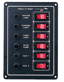
Unfortunately, it's slightly smaller than the original panel.
The good news is, the cost of the new panel is less than the cost of buying 6 circuit breakers. In addition, the circuit breakers, and internal wiring fit the original panel !
<post not complete>
Switch Panel Modification and Battery Box installation
------
I was told by the previous owners, that the wiring in the boat hadn't been used in the 5 years they owned the boat. They said they only day sailed.
Judging by the boats wiring, they were telling the truth.
There was a CD/Stereo with both power and speaker wires held together only with electrical tape, and a DC/AC Inverter, just sitting on the starboard bunk.
Previous owner's CD/Stereo and Inverter Wiring !
(I'm not sure what the OSB board was for... it came in handy for temporary hatchboards while the real ones are being varnished.)
Switch Panel with hanging wiring !
Judging by the fact the shielding for the VHF antenna cable was broken, the old installed VHF radio wasn't used either.
In fact the boat didn't have a battery box, or a battery.
My first task was to check all the wiring in the boat, to ensure that I wouldn't end up with a electrical fire when I installed a battery.
I visually traced and checked all the wiring, and their connections.
I was prepared for the worst, but in fact, the original wiring was in reasonable shape.
It was the badly done add-ons that were a problem.
I decided that I would remove anything that wasn't the basics and get the basic stuff up and running.
Tasks List:
-Remove unused wiring
-Remove CD/Stereo and all related wiring
-Clean and test DC/C inverter
-Redo any accessible splices that were not soldered and covered with waterproof heat shrink tubing.
-Test all hull lighting wiring for shorts and broken wire
-Redo connections to switch panel and replace fuses with circuit breakers.
-Replace deck connectors for radio antenna, and mast lighing
-Test all mast wiring for shorts and broken wire
-install battery box and battery
-test lighting, radio, and instruments
Removing unused wiring was simple once I figured out which wire was for what.-Remove CD/Stereo and all related wiring
-Clean and test DC/C inverter
-Redo any accessible splices that were not soldered and covered with waterproof heat shrink tubing.
-Test all hull lighting wiring for shorts and broken wire
-Redo connections to switch panel and replace fuses with circuit breakers.
-Replace deck connectors for radio antenna, and mast lighing
-Test all mast wiring for shorts and broken wire
-install battery box and battery
-test lighting, radio, and instruments
Yank, cut, etc... done.
Next I ripped out the complete CD/Stereo and all it's related wiring.
I don't plan to reinstall it. Who the heck uses CDs more than the single time to copy them to your media library ? What is this 1987 ?
Eventually I'll install a bluetooth connected, 12volt powered, ipod type speaker setup
I cleaned all the gunk and dirt off the DC/AC Inverter and tested it. Surprisingly it was in good shape. It has both direct connection and cigarette/power plug connections. I'll be wiring it with a direct connection once I figure out the rest of the wiring config.
Once I had all the unused wiring removed, the power connection for the base station radio needed to be redone. The connection consisted of crimp on quick connectors without any water protection.
The radio is currently mounted above the table, and the connection is up behind the wood trim on the hull deck joint. Since there is a risk of condensation or water leaks there, I removed the connectors and soldered in a 2 pin trailer connector along with some waterproof heat shrink. Using the 2 pin connector allows me to replace the radio in the future without having to cut and resolder the boat's wiring.
I used Permatex dielectric grease on the 2 pin connector to prevent corrosion.
(Contrary to many web posts, Dielectric grease doesn't prevent connections. It protects them from corrosion and prevents water ingress. The name simply means that it holds off high voltages over long paths, compared to other greases. Read the info from the manufacturer or contact them if you don't believe me.)
Once all the wiring and connections were cleaned up, I removed all the bulbs from all the lights, and disconnected the radio and instruments.
What I was doing, was ensuring that each wire on the boat, wasn't connected to another.
This way I could use a ohm meter to test for shorts between each conductor.
I did this because I had no way of visually checking the wiring hidden inside the pulpit tubing, and other inaccessible locations in the the hull.
By putting one test lead of the ohm meter on a single wire, and then putting the other lead lead on each of the other wires, making sure that each combination of 2 wires had full resistance (were an open circuit), I could tell if there were any serious shorts between the wires.
Now that I could trust the wiring, I tackled the switch panel.
-----
SWITCH PANEL
-----
Eventually I want to add additional equipment to the boat, including a solar panel.
In the meantime I thought I would upgrade the existing panel.
The original panel consists of 7 switches and 6 fuses.
The 7th switch is the main power switch and is not fused. it simply allows power from the battery to the rest of the switch panel.
One of the upgrades I wanted to do was to replace the fuses with circuit breakers.
When I was at my local chandlery I found this Victory Products 6 circuit switch panel, which also included decals to change the descriptions on the faceplate.
It was very reasonably priced, and I was hoping that it would simply replace the original panel.
Unfortunately, it's slightly smaller than the original panel.
The good news is, the cost of the new panel is less than the cost of buying 6 circuit breakers. In addition, the circuit breakers, and internal wiring fit the original panel !
<post not complete>
Last edited: