Every boats DC electrical system needs to start with a solid foundation. The foundation of any electrical system includes the battery system, charging system, switching and all the associated wiring and over-current protection.
This was a simple design I did for a boat the owner had already gutted to the bones. I say "simple" because the boat had no inverter, no windlass, no electric winches and only a very basic 120V system powering outlets, a charger and a water heater. This, by today's standards, is pretty simple.
When I am asked to make a drawing of the installed system I will ask the owner if they want an electrical layout drawn using standardized electrical symbols or an electrical layout using images of the actual installed products. Most boat owners, unless they are electrical engineers, simply don't understand electrical schematics or know what the symbols mean so they usually opt for a drawling like this one. There is no sense handing someone a drawing for their boats system if the language it's drawn up in is foreign to them.
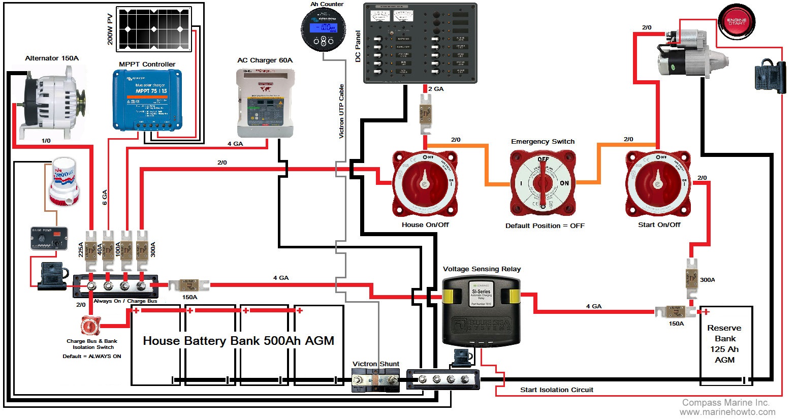
Battery Banks:
The batteries for this boat were chosen by the owner based on his desired engine run time, which he wanted to be very minimal. AGM batteries do charge a bit faster. His house needs included refrigeration and the desire to run two-three days on the hook before needing any engine recharging. While the bank wound up being 440Ah instead of 500Ah (shown) he can certainly do that with his Firefly AGM batteries which can be cycled to 80% DOD.. Of importance is the manner in which the house bank is wired. The negative comes off the right side of the bank and the positive off the left. This helps to keep the bank well balanced. Also note that nothing in the DC negative side connects to the battery negative terminal before the shunt for the battery monitor.
Busbars:
Busbars are a very good way to wire batteries on most boats larger than about 27'. This keeps the number of terminals on the battery posts to a bare minimum and allows for a clean, neat, orderly and well labeled installation. Off the positive side of the house bank the first thing we hit is the unswitched/charge busbar. This busbar wound up within 7" of the battery terminal thus the fusing was off the multi ANL fuse bus. If the busbar is more than 7" a fuse between the busbar and battery would be a good idea and an ABYC requirement unless you sheath the positive wire. The only fuses suitable for a bank of this size are MRBF, ANL or Class T.
The unswitched/charge bus is just what it says. It is used to power bilge pumps, this boat had three, (not all are shown) and collect all the charge sources. If an inverter, inverter/charger or windlass were installed this would be the take off for that large gauge wiring as well. On this busbar are:
Alternator
Bilge Pumps
Solar
Battery Charger
House Bank On/Off Switch
ACR Combing Relay
The negative side busbar collects all DC negatives on the system or "load" side of the shunt. Of importance is the position of the engine negative cable. I purposely place the engine negative cable on the ear of the starter motor. This removes rusty, corroded and multiple dissimilar poorer conducting metals in the negative path and leads to better cranking performance.
Safety:
Anything connected to either battery bank is over-current protected including the ACR, alternator, solar, battery charger and DC panel. You will note that the fuse going to the HOUSE ON/OFF switch is 300A. This is so that when or if the house bank needs to be used to start the motor it won't trip. Immediately after the HOUSE ON/OFF switch there is another fuse where the wire gauge steps down to feed the DC panel. This fuse is after the emergency parallel wiring so that starting the motor does not affect the house panel fuse.
Another safety feature is the Alternator Service Disconnect Switch. Because the alternator is fed direct to the house bank for optimal charging performance this switch is a worthwhile investment in safety. This is a switch clearly marked and labeled inside the engine room so that techs or the owner working on the engine can turn off the alternator feed when working on the engine. I use the Blue Sea mSeries switches for this.
The "emergency switch" can serve to parallel banks, use house for everything use start for everything and isolate either start or house in the event of a bank failure. It can also be used to charge both banks should a fault occur in the ACR.
Charging:
On this boat the alternator is the prime mover of bulk charge current. It is set up to deliver about 125A of charge current, a .28C charge rate, to the house bank. The regulator (not shown in diagram) is a Balmar MC-614 with battery and alt temp sensors. The shore charger is only used for equalizing and charging when the owner visits a dock. The boat is also equipped with a 200W solar array with the panels wired in parallel to minimize shading issues. The starting battery is charged via the ACR and activates whenever a charge source is present. The ACR is also wired for start isolation. The start isolation feature "SI" isolates the START bank from HOUSE the split second the starter switch is depressed and reverts to normal operation once the engine is started. With solar the banks could be in parallel during starting so start isolation is a good feature when you have a three ON/OFF switch configuration. The ACR also has an ON/OFF toggle switch in the negative so the owner could turn it off if he so desired (not shown)
Switching:
This owner was starting from scratch and as such I chose to use the three ON/OFF switch configuration. HOUSE SWITCH<>EMERGENCY SWITCH<>START SWITCH. Normal use isolates the house loads from starting loads however the middle emergency switch can be used to do starting and house loads from either bank while isolating the other. The emergency switch is purposely place on the load side of each ON/OFF so that either bank could be 100% isolated in the event of a bank failure. I use a "keyed" ON/OFF switch with the key on a lanyard. This little key on a lanyard trick stops most guests from using the middle switch.
Hidden House Bank Isolation Switch (lower left of image):
For this installation a battery switch was installed (lower left) to completely isolate the house bank from all charging and loads in the event of a failure. The switch is physically located inside the battery compartment right next to the bank.
In the event that there were a house bank failure, the owner can isolate the house bank then turn on the emergency parallel switch and all charging previously feeding directly to the house battery can now be used when relying on the start/reserve bank. Default position for this switch is always on...
This owner also added a Balmar Smart Gauge to the boat when he realized how much work the Ah counter was to keep calibrated.. There are many more options one could change, modify or add but this is a pretty typical cruising boat foundation for a 27-40 +/- footer these days..
This was a simple design I did for a boat the owner had already gutted to the bones. I say "simple" because the boat had no inverter, no windlass, no electric winches and only a very basic 120V system powering outlets, a charger and a water heater. This, by today's standards, is pretty simple.
When I am asked to make a drawing of the installed system I will ask the owner if they want an electrical layout drawn using standardized electrical symbols or an electrical layout using images of the actual installed products. Most boat owners, unless they are electrical engineers, simply don't understand electrical schematics or know what the symbols mean so they usually opt for a drawling like this one. There is no sense handing someone a drawing for their boats system if the language it's drawn up in is foreign to them.
Battery Banks:
The batteries for this boat were chosen by the owner based on his desired engine run time, which he wanted to be very minimal. AGM batteries do charge a bit faster. His house needs included refrigeration and the desire to run two-three days on the hook before needing any engine recharging. While the bank wound up being 440Ah instead of 500Ah (shown) he can certainly do that with his Firefly AGM batteries which can be cycled to 80% DOD.. Of importance is the manner in which the house bank is wired. The negative comes off the right side of the bank and the positive off the left. This helps to keep the bank well balanced. Also note that nothing in the DC negative side connects to the battery negative terminal before the shunt for the battery monitor.
Busbars:
Busbars are a very good way to wire batteries on most boats larger than about 27'. This keeps the number of terminals on the battery posts to a bare minimum and allows for a clean, neat, orderly and well labeled installation. Off the positive side of the house bank the first thing we hit is the unswitched/charge busbar. This busbar wound up within 7" of the battery terminal thus the fusing was off the multi ANL fuse bus. If the busbar is more than 7" a fuse between the busbar and battery would be a good idea and an ABYC requirement unless you sheath the positive wire. The only fuses suitable for a bank of this size are MRBF, ANL or Class T.
The unswitched/charge bus is just what it says. It is used to power bilge pumps, this boat had three, (not all are shown) and collect all the charge sources. If an inverter, inverter/charger or windlass were installed this would be the take off for that large gauge wiring as well. On this busbar are:
Alternator
Bilge Pumps
Solar
Battery Charger
House Bank On/Off Switch
ACR Combing Relay
The negative side busbar collects all DC negatives on the system or "load" side of the shunt. Of importance is the position of the engine negative cable. I purposely place the engine negative cable on the ear of the starter motor. This removes rusty, corroded and multiple dissimilar poorer conducting metals in the negative path and leads to better cranking performance.
Safety:
Anything connected to either battery bank is over-current protected including the ACR, alternator, solar, battery charger and DC panel. You will note that the fuse going to the HOUSE ON/OFF switch is 300A. This is so that when or if the house bank needs to be used to start the motor it won't trip. Immediately after the HOUSE ON/OFF switch there is another fuse where the wire gauge steps down to feed the DC panel. This fuse is after the emergency parallel wiring so that starting the motor does not affect the house panel fuse.
Another safety feature is the Alternator Service Disconnect Switch. Because the alternator is fed direct to the house bank for optimal charging performance this switch is a worthwhile investment in safety. This is a switch clearly marked and labeled inside the engine room so that techs or the owner working on the engine can turn off the alternator feed when working on the engine. I use the Blue Sea mSeries switches for this.
The "emergency switch" can serve to parallel banks, use house for everything use start for everything and isolate either start or house in the event of a bank failure. It can also be used to charge both banks should a fault occur in the ACR.
Charging:
On this boat the alternator is the prime mover of bulk charge current. It is set up to deliver about 125A of charge current, a .28C charge rate, to the house bank. The regulator (not shown in diagram) is a Balmar MC-614 with battery and alt temp sensors. The shore charger is only used for equalizing and charging when the owner visits a dock. The boat is also equipped with a 200W solar array with the panels wired in parallel to minimize shading issues. The starting battery is charged via the ACR and activates whenever a charge source is present. The ACR is also wired for start isolation. The start isolation feature "SI" isolates the START bank from HOUSE the split second the starter switch is depressed and reverts to normal operation once the engine is started. With solar the banks could be in parallel during starting so start isolation is a good feature when you have a three ON/OFF switch configuration. The ACR also has an ON/OFF toggle switch in the negative so the owner could turn it off if he so desired (not shown)
Switching:
This owner was starting from scratch and as such I chose to use the three ON/OFF switch configuration. HOUSE SWITCH<>EMERGENCY SWITCH<>START SWITCH. Normal use isolates the house loads from starting loads however the middle emergency switch can be used to do starting and house loads from either bank while isolating the other. The emergency switch is purposely place on the load side of each ON/OFF so that either bank could be 100% isolated in the event of a bank failure. I use a "keyed" ON/OFF switch with the key on a lanyard. This little key on a lanyard trick stops most guests from using the middle switch.
Hidden House Bank Isolation Switch (lower left of image):
For this installation a battery switch was installed (lower left) to completely isolate the house bank from all charging and loads in the event of a failure. The switch is physically located inside the battery compartment right next to the bank.
In the event that there were a house bank failure, the owner can isolate the house bank then turn on the emergency parallel switch and all charging previously feeding directly to the house battery can now be used when relying on the start/reserve bank. Default position for this switch is always on...
This owner also added a Balmar Smart Gauge to the boat when he realized how much work the Ah counter was to keep calibrated.. There are many more options one could change, modify or add but this is a pretty typical cruising boat foundation for a 27-40 +/- footer these days..

