Going to update the 12v system on my new, to me, Beneteau First 305. Would like to get feedback from others on my plans starting with my wiring diagram (attached).
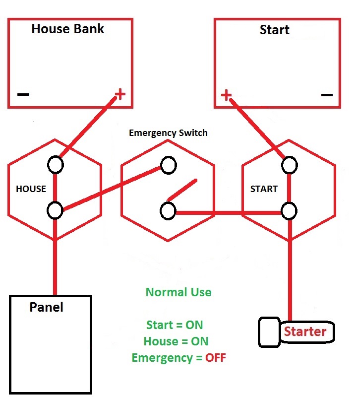
Presently there are 3 handles, in the head, that control the power. The first (Black) is the main power and the other 2 (Red) determine which battery bank will be drawn from.
My plan is to change to 1/2/Both switch and move it to under the companionway (above the engine). I've been staring at locations for the switch and the accompanying ACR and busbars and that seems to be the best location (for ease of switching and proximity to batteries and engine). If anyone, with familiarity with the mid-80's First series, has other suggestions please let me know.
Any feedback on wiring diagram is greatly appreciated. Solar panel will be 50W, with Morningstar PWM Controller.
Regards,
Bob
Beneteau First 305
Attachments
-
48.9 KB Views: 451