Battery switch does not kill power

Feb 21, 2018
31
- -
HI all,
I bought this boat a year and a half ago and noticed this problem while performing the initial survey before purchase. The surveyor noted the problem and suggested it be fixed (among others), but otherwise considered the vessel "seaworthy". About six months ago, I redesigned and replaced the batteries and all components (bus bars, ground terminals, isolator, combiner, breakers, cables/wires, terminal ends, fuses, etc...) within the box, including the battery switch. the system (including an inverter) was engineered by Northern Arizona Wind and Sun and they also reviewed my install diagrams to confirm. Despite the success of the install, it did not seem to resolve the issue. I had been so excited about all my new goodies and the increased performance of the electrical system, that I called the project a success and sort of left that nagging little tidbit about the battery switch in the background.

Well, the honeymoon has faded and my concern is re-emerging. I am wondering if I have a ground fault from the distribution panel. All of this wiring is original (1987) or at least upgraded from previous owner. I have replaced a couple of DC circuits as well as the AC wiring (for a galvanic isolator and the inverter), but main positive and negative are original. My next step is to begin to troubleshoot this and see if I can isolate where the problem really is.

Does anyone out there know anything about this? I am very much amateur and consider all things electrical as black magic. I have recently mounted (2) 320 watt solar panels and I am itching to connect, but worry about the battery switch problem.

The boat is a 1987 Hunter Legend 37.
Inverter is Victron Multiplus 3000
Batteries are (3) 100 ah Battleborn Lithium Ion + (1) West Marine AGM starting battery
Not sure what else might be relevant to help understand the issue

Thanks!
 
Jan 11, 2014
11,323
Sabre 362 113 Fair Haven, NY
It is a bit difficult to offer much help based on your description. A copy of the schematic would go along way to sorting out the issue.
 
Feb 21, 2018
31
- -
Yes, of course, a splendid idea!

This was the original schematic. I have since made some minor changes, but should work just fine for this discussion.

Peregrine Electrical.jpg
 
Jan 11, 2014
11,323
Sabre 362 113 Fair Haven, NY
I don't see an obvious answer to your concern about the battery switch not depowering the panel, however, there are a couple of things I did notice.

First the solar panels. Your panels are wired in series and then to the controller. This works well for land based systems, not as well for boats. The issue is shading. When a panel is partially shaded, by a boom, rigging, awning, sail or whatever, the output can be significantly decreased. When the panels are in series this affects the total output. A more robust system has a controller for each panel with the panels placed in parallel after the controller. If one panel is compromised by shade or other failure, the remaining panel continues to provide power. This isn't as much an issue on land based systems because the panels can be optimally oriented and placed so that shading does not occur. There are also advantages to running high voltage, low current circuits in that smaller gauge wires can be used.

The schematic shows both a battery combiner and an isolator. This seems puzzling, because I'm not sure about the functions of each device. The isolators I know of are diode based and allow 2 battery banks to be poorly charged from one source. Battery combiners serve a similar function but have a big advantage if they use relays and not diodes. I'm not sure why this system would have both and that may be part of the problem. The device I am most familiar with is a Blue Sea ACR. In your system it would sit in between the house bank and the start bank.

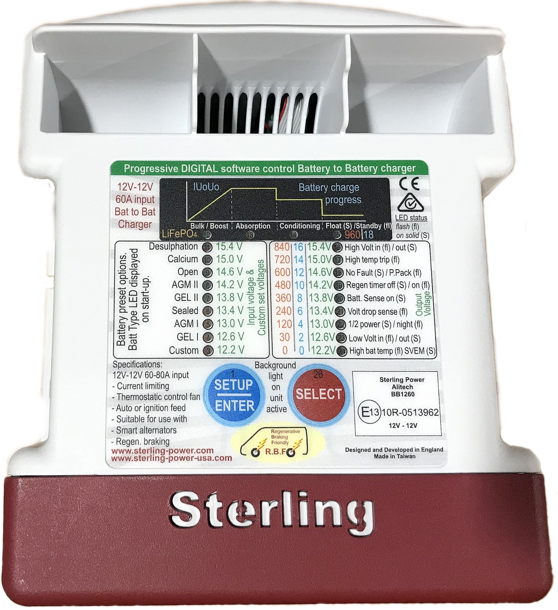
Another potential issue is the charging profiles for the house bank and start bank. You are mixing chemistries which will take different charging profiles; perhaps that's why you have the combiner and isolator? I think a simpler system would use a battery to battery charger, like this one:


The person you want to talk to is @Maine Sail either here on SBO or through his website, MarineHowto.com.
 
May 17, 2004
5,032
Beneteau Oceanis 37 Havre de Grace
What is the model of the battery switch?
Is the problem when you’re disconnected from AC, or only when you’re connected to shore power?
There seems like there might be some funny business with the combined and isolater. I’d expect those to be connected to the battery side of the main switch, not the downstream side. Not sure yet about how they work to say if that’s the problem, but it may deserve closer inspection as it’s certainly a way for power to get around the switch. If that’s what’s happening it’s not ideal as it means house loads are draining the start battery.
 
May 17, 2004
5,032
Beneteau Oceanis 37 Havre de Grace
Also, I would expect the combiner to combine the batteries when they are charging, so they could share a charging source. That has the one potential issue dlochner pointed out of the dissimilar chemistries. It also has the problem of being connected through a 10A fuse to the house bank. If the combined starts combining when the alternator is charging the bank, I’d think the alternator could push more than 10A and blow that fuse. So something definitely seems strange in that area.
 
Feb 21, 2018
31
- -
Thanks for the replies.

@dlochner , The panels , I figure, can be an ongoing experiment and I'm starting with this setup. I may possibly switch down the line, but I'd like to get some hard data to work from before doing so.

The Combiner and Isolator setup was and still is a bit confusing to me, but I put my faith in the engineer from NAWS and he seemed pretty confident. Essentially, the combiner (Link here) is intended to combine the batteries within a prescribed voltage range and separate them when they are above or below that level. The Isolator, is pretty much a beefed up relay (or?) diode to assist the combiner with larger amperages (?).

The inverter is also a charger and so controls the charging profile for the house bank. The combiner is then set to take that profile and use the programmable voltage window to feed (trickle?) the start battery. I understand that this is only the case when the batteries are being charged on shore power and I plan on looking at a voltage regulator to supplement the alternator for when away from shore power and the solar panels are not enough.

Is @Maine Sail for hire or conversation? I think I remember perusing his website for inspiration during the design process.

@Davidasailor26 The switch is a Blue Sea something or other. I don't remember the model, but it was previously being used on a wind generator system that the previous owner removed. The switch fits well on the battery box and so I decided to use it despite being rated for 350 amps instead of the much larger 400 amp blue sea version.

The problem is repeatable regardless of the presence of AC power.

I do believe that house loads are draining the start battery.

You have a point with the 10 amp fuse on the combiner. I believe that the alternator is rated for 50 amps but I have not been able to use it to charge the batteries since I have installed the new components.

It seems as if I have put too much faith in the engineer at Northern Arizona Wind and Sun...
 
Jan 11, 2014
11,323
Sabre 362 113 Fair Haven, NY
It seems as if I have put too much faith in the engineer at Northern Arizona Wind and Sun...
A quick response. There are significant differences between land and recreational marine solar installs. NAWS may be an excellent source for off-grid or RV installations, however, the devil is always in the details.

Is @Maine Sail for hire or conversation? I think I remember perusing his website for inspiration during the design process.
Yes he is. Check his website, www.MarineHowTo.com there is information on his site.
 
Apr 22, 2011
865
Hunter 27 Pecan Grove, Oriental, NC
The Blue Seas selector switch isolates the house batteries but not the start battery. To isolate the start battery from the dc circuit, you will need to insert a selector switch between the the start battery bus bar and the other loads. If you plan on using your alternator to charge both the start and house batteries and using the circuit system that you have in place, I would either externally regulate your alternator or install a dc to dc convertor to reduce the amperage draw on your alternator. Those three battle borns will demand 100 percent of your alternator and likely overheat it without some type of regulation.
 
Feb 26, 2004
22,760
Catalina 34 224 Maple Bay, BC, Canada
You might want to consider going back to square one. Dave's right. Get rid of the isolator, the ACR takes care of that.

Here's how:

OEM 1-2-B Switch Wiring History Alternator/Batteries & "The Basic" 1-2-B Switch BEST Wiring Diagrams

Basic Battery Wiring Diagrams This is a very good basic primer for boat system wiring: Basic Battery Wiring Diagrams

This is another very good basic primer for boat system wiring: The 1-2-B Switch by Maine Sail (brings together a lot of what this subject is all about)
1/BOTH/2/OFF Switches Thoughts & Musings

This is a newer primer for boat system wiring design with a thorough digram: Building a Good Foundation (October 2016)
Building a DC Electrical Foundation

The Short Version of the 1-2-B Switch Stuff: Electrical Systems 101 This is a link to the Electrical Systems 101 Topic, reply #2

What are ACRs, Combiners & Echo Chargers? (by Maine Sail) [scroll to the top]
Battery Switch Question ? and Battery isolator / voltage regulator / batteries

Making Sense of Automatic Charging Relays (2019)
Making Sense of Automatic Charging Relays
 
Apr 8, 2010
1,942
Ericson Yachts Olson 34 28400 Portland OR
I am not educated enough to understand all the parts and functions downstream from your main switch. What might be best is to start making a field diagram of the positive's from the master switch area. And then diagram any wiring that goes directly to any battery.
My main concern is that when I turn the main (1-2-all) switch to "Off" .... everything really must be powered down. It just does not seem safe, otherwise.
 

Tom J

.
Sep 30, 2008
2,301
Catalina 310 Quincy, MA
Hopefully, Maine Sail will check in on this, but it seems to me that your circuit as it exists defeats the purpose of the battery switch. I think you would want your house bank to be connected to one terminal of the batt switch, the start battery to another terminal, and the center terminal to the positive bus bar or distribution panel, etc. Adding devices to the battery switch doesn't seem to work very well. Other switches can be added to control those devices, but the battery switch needs to control the batteries.
 

walt

.
Jun 1, 2007
3,511
Macgregor 26S Hobie TI Ridgway Colorado
Drive by response.. and Im not even sure I understand what problem you are having.. but the battery switch may just be disconnecting the battery from a 12 volt distribution. Even when that battery switch is open, the solar charge controller is likely still connected to that 12 volt distribution. When the sun is shining, that solar controller may be putting out a voltage sort of similar to what battery voltage is on the 12 volt distribution. If you are measuring that distribution, you would see some 12 volt reading even though the battery is completely disconnected.

If you throw a tarp over the solar panels so that the charge controller completely shuts off, do you still have the problem. ..

Anyhow.. drive by response and I admit to not reading everything.. so could be way off.
 
  • Like
Likes: LloydB
Feb 21, 2018
31
- -
Thank you all for your thoughts and replies. It seems as though the general consensus is that there may be an issue with the relationship between the House and Starter battery banks, specifically the Isolator. However, because the problem mentioned in my original post existed before the installation of this system, I was skeptical that the isolator or combiner were the cause. So this morning, I ran through a quick experiment, which might help put us back on track towards solving the root cause. My experiment went thusly:

  1. All systems on
  2. Unhooked Starter negative - battery switch did nothing
  3. Disconnected Starter positive - battery switch did nothing
  4. Switched off shore power - battery switch killed all power at every position except both
  5. Reconnected Starter positive - everything remained off
  6. Reconnected Starter negative - Combiner status light turned on (connected directly to starter battery), battery switch did nothing in all positions, everything else remained off
  7. Switched on shore power with battery switch OFF- All systems turned back on, battery switch did nothing
There was a previous post about shore power and I think I responded incorrectly. I thought I had tried this before, but I must be mis-remembering. This test obviously reveals that the shore power is bypassing the switch AND supplying DC power. I don't understand how this could be happening as shore power is AC and the only method that I have to convert to DC is through the Inverter, which is connected aaaaannnnnddddd I am just now realizing what the issue is...

I suppose I will share since you are all now invested. I am attaching a few images:
1.The battery selector switch that I am using
2. The wiring on the backside of this switch
3. A more updated diagram of the system

I have the positive cable from the inverter sharing a terminal with the positive cable supplying the main positive DC bus bar. This would negate any effects of the switch because the two cables are permanently connected. Duh.

Next question, which cables should go to which posts? Remember that this is not really a battery selector switch as that job is assumed to be accomplished by the Combiner / Isolator system. This is essentially an emergency shut off / Inverter - Battery Bank Selector Switch. I'm thinking the house bank and solar cables goes to common, the inverter goes to post 1 and the pos. bus bar goes to 2?
 

Attachments

May 17, 2004
5,032
Beneteau Oceanis 37 Havre de Grace
Victron has a schematic at https://www.victronenergy.com/uploa...olt-system-example-with-Argo-Fet-and-MPPT.pdf. It’s a much more complex system than yours, but fundamentally they are using two on/off switches rather than one 1/2/B switch. The positive battery cable feeds two on/off switches. One controls current to/from the inverter/charger, and the other controls current to the house loads. The problem with using a single 1/2/B switch is that you have to choose between separating the inverter from the battery or the house loads, but you can’t cut it out completely. Right now the switch isolates the battery from the inverter. Alternatively you could put the house loads on the currently unused switch post, and put the inverter on the same post as the batteries. Then you could use the switch to isolate the inverter from the loads, but it would always be connected to the batteries.
 
Feb 21, 2018
31
- -
Thank you so much.
I think your suggestion is valid, but for the sake of theoretical argument, I wonder what you think of leaving the setup as is? The benefits include:
1. Current system functions - if it ain’t broke...
2. In the event of emergency:
A. Shore power - I shut down shore power and shut down battery switch. All power is isolated in two moves
B. No shore power - I shut down battery switch and all power is isolated in one move.

This may have been my intention all along but I don’t remember because the design process was filled with lots of education and compromise and hundreds of individual decisions.

I realize that all of this discussion may appear as if I am simply trying to prove my point, but I assure you that it is not. I am still very much new to and in awe of electrical design and greatly appreciate any feedback that may serve to increase my safety, comfort, and knowledge. Plus if other readers find it helpful, that’s cool too. thanks again.
 
Jan 11, 2014
11,323
Sabre 362 113 Fair Haven, NY
@Marrigoround as you are learning there many factors to consider when designing an electrical system for a boat. The top priority is safety, adequate supply and ease of use are two more. Perhaps the second most important is making the system idiot proof or as some say, "brother-in-law" proof.

There are 2 types of energy sources on the boat, regulated and unregulated. Regulated sources are those that have built in limits, the alternator can not produce more electricity than it was designed for, same for the solar panels and charger. The unregulated source is the battery(s). These need to be properly fused and easily and quickly isolated.

A simple design has 2 on/off switches one each for the start bank and house bank. These switches need to be after a fuse and before any other load or charging connection. A third switch is used to power up the rest of the system, DC panel and starter. This switch needs to be simple; turn one click and the house and start batteries are connected to their respective loads. Turn another click and the batteries are combined and power up both starter and panel. Blue Seas makes such a switch (Blue Sea 5511e). If one bank should fail, the bank's on/off switch is turned off and the main switch (5511e) is put in the both position. This allows the house bank to start the engine or start bank to power house loads. Being able to isolate the banks helps to prevent a bank battery from killing off the rest of the batteries in the system.

One of the links @Stu Jackson provided probably have a schematic of this kind of system. (Stu's much better than I am at keeping track of those links.) Spend some time with those links.
 
Feb 6, 1998
11,667
Canadian Sailcraft 36T Casco Bay, ME
"Battery Switch does not kill power."

Focus on this image... Then read: 1/BOTH/2/OFF Switches Thoughts & Musings and focus on the purpose of the "C" post or COM.


Best to stick with marine specific companies, that are ABYC certified & their designs are compliant, when doing marine electrical design/layout. For example there is no battery switch for your starting battery. This is an ABYC requirement for a battery of your type.

Also, being a pioneer and installing LiFePO4 batteries before the ABYC Li-Ion standards are finalized could carry some insurance risk in an insurance survey. For example, what if the ABYC standards require the BMS be able to communicate externally for safety reasons?

Where is your alternator connected to the system? It is not shown...
 
Feb 21, 2018
31
- -
@Maine Sail, thanks for chiming in. According to your linked article, it looks like I will need to rewire the switch to include the use of the common post. I was relieved to see that you also include the use of an ACR system similar to mine. I am, of course, using a Magnum Energy Smart Battery Combiner along with a 200 amp isolator, but the theory sounds the same. I've only made it about half way through this article, but look forward to some down time in the next couple of days to further absorb.

The use of a non-marine consultant/dealer is only now becoming apparent to me. I like to think that the issues are small enough, that with the help of the great internet hive mind, I can get the system up to snuff without any safety concerns or taking out a mortgage. Unfortunately, the engineer who was helping me, assured me that he has worked on dozens of systems for boats, begging the question; who else has been left non-compliant and underserved?

My alternator is connected to the system directly to the start battery (see diagram post from Saturday).

So, it seems like I will need to rewire the switch thusly:
C - Distribution panel, charger/inverter, alternator
1- House Bank
2- Start battery

There was a previous post mentioning the danger of connecting the alternator to the 300Ah LiFe04 house bank. "Those three battle borns will demand 100 percent of your alternator and likely overheat it without some type of regulation. " - Heritage
I have only begun to research voltage regulators, so if there is a danger of damaging my alternator, I may need to hold off on rewiring the switch until I have the proper protection.

Do I have this correct?

@Stu Jackson Thanks for the reminder. Sometimes it is nice to have these things stated explicitly.