Aqua signal series 25 Deck/Steaming light

Db421

.
Jun 7, 2004
95
Hunter 34 1986 Lake Lanier, GA
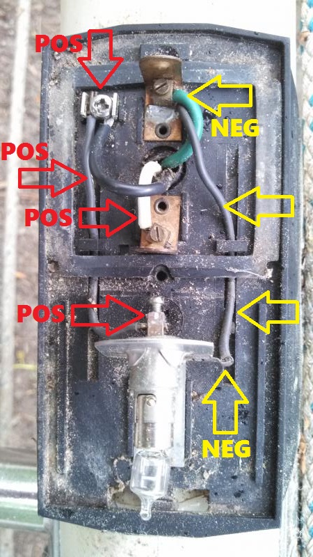
I'm re-wiring my mast lighting and am having trouble wiring a combo deck/steaming light. I pulled the fixture off a sister ship and I can't seem to figure out how to wire it so that I can switch the lights independently at the panel. there are three wires controlling two bulbs. When I mock up the circuits I can only get one or the other lights to light up, but not both. I would like to be able to switch either on separately or have them both on at the same time if needed. Here is a pic of the fixture as it sits in the mast. The green. black & white wires coming out in a spiral pattern are the ones going to the panel. The green and black may be reversed from OEM. Any help would be greatly appreciated. Thanks!

Edit: the light bulb on the left was removed for clarity, steaming light on left, deck light on right.


IMG_20140422_183131_874.jpg
 
Last edited:
Feb 17, 2006
5,274
Lancer 27PS MCB Camp Pendleton KF6BL
So the way I see it, Green and White form one circuit and Black and Green form the second circuit. When you tied White and Black together, both lights did not come on?
 
Oct 30, 2011
542
klidescope 30t norfolk
Steaming light

What ya got there is missed colored wires the green is common ground which should be connected to ground bus black wite coming from negative terminal on batteries there Florence black nav lights and white deck light switch
 

MrUnix

.
Mar 24, 2010
626
Hunter 23 Gainesville, FL
Assuming the bulb on the right of the picture is your steaming light and the deck light is behind the section on the left, then you have Green as common ground, white is your deck light and black is the steaming light. Should not be a problem having both on at the same time.

Cheers,
Brad
 
Oct 9, 2013
72
Beneteau First 38 Belmont Harbor
Hi,

I have marked up your pic to show the following:

- I have inserted a box to indicate where another lamp (steaming lamp) needs to be inserted.
- The lamp on the right side is the deck lamp and points downward (to the right in your photo) and slightly forward.

- Three wires exit from the mast to the light fixture (green, white, and black)
- The green wire is the negative for both lamps. It is first connected to the metal contact for the left side lamp (1st purple circle) and is then connected to the metal contact for the right side lamp (2nd purple circle). It serves as the negative connection for BOTH lamps.
- The white wire is the positive to the steaming lamp on the left side (yellow circle)
- The black wire is the positive for the deck lamp on the right side (black circle)

PDF of product datasheet from Aqua Signal is attached.

So – just 3 wires up the mast to allow you to operate each lamp separately.

Doug in Lakeview
1984 Beneteau First 38 – Hull #178
Belmont Harbor – Chicago
 

Attachments

Db421

.
Jun 7, 2004
95
Hunter 34 1986 Lake Lanier, GA
Thanks for the quick replies all,

Brad, what you are saying it what I expected, and what happened when I hooked everything up directly to the battery. When I tried to wire it up through a panel, I wasn't able to switch the lights independently. Now when I hook it all up directly, I can only get the steaming light (left hand in the photo) to light up. I either blew the deck light bulb or have other issues.

Again, I appreciate the input, thanks!
 

Db421

.
Jun 7, 2004
95
Hunter 34 1986 Lake Lanier, GA
Doug,

Thank you very much. You're reply came in just as I was sending out a general thank you to the other posts. Your answer is what I originally thought was the case, but see my response to Brad. Somehow this doesn't allow me to switch the lights separately. I'm running the green to battery neg (neg bus bar) and the black & whites to separate switches on the panel. Do you think I'm missing something there?
 
Feb 17, 2006
5,274
Lancer 27PS MCB Camp Pendleton KF6BL
If you have a volt meter you can test for voltage on the contacts. It is possible that corrosion has set in and all you need to do is remove the wires, clean them up and then reattach them. And, it is possible like you said that the bulb is burnt out. If you are getting 12v at the connectors then that is the likely scenario. The worst case is the wiring in the mast is shot and needs to be replaced.
 
Feb 6, 1998
11,701
Canadian Sailcraft 36T Casco Bay, ME
Doug,

Thank you very much. You're reply came in just as I was sending out a general thank you to the other posts. Your answer is what I originally thought was the case, but see my response to Brad. Somehow this doesn't allow me to switch the lights separately. I'm running the green to battery neg (neg bus bar) and the black & whites to separate switches on the panel. Do you think I'm missing something there?
Someone used AC wiring for your DC light so no telling if there are other anomalies in there. best to continuity test the circuit and make sure green stays green the whole way, white stays white the whole way and black stays black the whole way.

If you had the light in your hand, and only two feet of wire, white to +/green to - would light the steaming/masthead light and black to + and green to - would light the deck light
 
Oct 26, 2008
6,236
Catalina 320 Barnegat, NJ
It seems to me that you have to figure out which one is the common ground, the rest should fall into place. I have a similar light and it functions perfectly just as you desire and there are only 3 wires, but black is the common ground (neg) on mine, I believe (HELLA).

My bet is that we are misleading you on the common ground for DC wiring. I always thought that the old system was red is positive and black is negative. (Now, yellow is negative). Low voltage wiring always seem to have a variety of colors for positive but black always seems to be neg.

I bet your common ground is black. White and green are your positives. From the tangle of wires, it looks to me that the 2 blacks come together at one buss in the lower left of the picture. I would guess that is common neg.

BTW, green is the ground for a 3-wire AC system, black is hot and white is neutral. So the colors can definitely be misleading.

Try the black as common ground and see how it works. Make sure your bulbs are good.
 
Oct 26, 2008
6,236
Catalina 320 Barnegat, NJ
Basically, you are getting either one or the other on because you haven't identified the common ground (neg). The bulb doesn't care which way he current goes thru it, so by connecting the common ground to one of the positives, you only get one or the other on by flipping the switches, but you can't get both on at the same time. You can only get the lights to function the way you want by identifying the common ground (neg). Again, my guess is black.
 
Sep 15, 2009
6,243
S2 9.2a Fairhope Al
Basically, you are getting either one or the other on because you haven't identified the common ground (neg). The bulb doesn't care which way he current goes thru it, so by connecting the common ground to one of the positives, you only get one or the other on by flipping the switches, but you can't get both on at the same time. You can only get the lights to function the way you want by identifying the common ground (neg). Again, my guess is black.
Scott if you look close at the pic you will see that the green wire in his pic is the only wire that goes to both bulb holders ...the green wire has a jumper to the second holder...the white goes to one and the black goes to the other ....if i am seeing this correctly black and white are the + wires for the lights and if you switch them on the panel with individual switches you can run either /or and both by the switches......

regards

woody
 
Oct 26, 2008
6,236
Catalina 320 Barnegat, NJ
Look at the screw heads ... The Phillips head clearly has the black leading to 2 separate posts on separate lights. The slotted heads are the positives. White coming from a hole leading into the past goes directly to a post on the light. Green (coming from that same hole) goes to a post with a jumper going over to the other light. Green and white are the positives, no?
 
Sep 15, 2009
6,243
S2 9.2a Fairhope Al
No...green is the only one that goes to both via a black jumper ...if green was one of the pos wires then both lights would burn at the same time... then white and black would have to be the neg wires......look at the pic with the circles and it will come to you ........

regards

woody
 
Oct 26, 2008
6,236
Catalina 320 Barnegat, NJ
Actually, it looks like there is a slotted head at the underside of the bulb to the right. It looks possible that the wiring may have been reversed on that bulb as well. The connection at the top right looks like it should lead to the Phillips head and the jumper should go to the slotted head underneath the bulb.

Still, I believe the Phillips head is neg.
 
Sep 15, 2009
6,243
S2 9.2a Fairhope Al
the Phillips head is like a junction connect feeding both fixtures as the neg.....

regards

woody

correction the Phillips head is a junction for the light to the right feeding pos to that fixture
 
Oct 26, 2008
6,236
Catalina 320 Barnegat, NJ
The photo with the circles has some sort of phantom jumper which is confusing the issue. That jumper doesn't exist in the original picture. The only screw head that has a common lead with both bulbs is the Phillips head. Whichever wire that is connected on the other side of that screw head is the common neg, right? I think the common theme is that he has to identify which wire is common negative. The definition of insanity would be to continue using the same wire as negative when it certainly doesn't allow the lights to function properly.
 
Feb 6, 1998
11,701
Canadian Sailcraft 36T Casco Bay, ME
At the fixture:

PURPLE CIRCLES / GREEN TO COMMON BLACK = COMMON NEG

BLACK CIRCLE / BLACK = DECK LIGHT POS

YELLOW CIRCLE / WHITE = MASTHEAD LIGHT POS

The problem is once they leave that fixture we have no idea what someone did between the fixture and the panel.


Feb 6, 1998
11,701
Canadian Sailcraft 36T Casco Bay, ME
The photo with the circles has some sort of phantom jumper which is confusing the issue. That jumper doesn't exist in the original picture.
There is no difference in the photos other than the added circles...

The only screw head that has a common lead with both bulbs is the Phillips head.
No, the only screw that touches both fixtures is the green wire that converts to black at the top terminal.. The phillips head only touches the center post of the halogen deck light.
 
Sep 15, 2009
6,243
S2 9.2a Fairhope Al
At the fixture:

PURPLE CIRCLES / GREEN TO COMMON BLACK = COMMON NEG

BLACK CIRCLE / BLACK = DECK LIGHT POS

YELLOW CIRCLE / WHITE = MASTHEAD LIGHT POS

The problem is once they leave that fixture we have no idea what someone did between the fixture and the panel.


thanks Maine for correcting me...i corrected my post to reflect your assessment .... need another cuppa lol...as Bob Shane said in the song MTA..."this a time that try's men's soles" and the time i would replace all that wire with new starting from scratch so when i turn on my lights i wouldn't worry lol....anything worth doing is worth doing right ....

regards

woody