Another wiring diagram for review

Feb 8, 2009
118
Sabre 34 MK-1 Annapolis, MD
Your latest diagram looks nice. Of course, I still have comments! :)

The starter fuse/line is a huge upgrade from your original, but will make a solid install. With Main's comments on fuse size and over-rating, you could even make the 175A fuse a 200A or 225A (#2 is rated 160 in engine spaces). That would ensure it never blows. The fact that your 1/2 switch is 5-6 feet from the batteries does mean the run to the starter is fairly long, so the #2 helps with that.

You've added the bilge pump to the diagram. Now you are up to 6 items that are "always hot." Then you show a shunt, which means you are planning on a battery meter (and you already probably have a volt meter), so that is another line. How about this idea:
* Drop the 125A to 60A. Still adequate for the alternator current.
* Keep the Alt line at #4 for voltage drop issues.
* Get a bus bar, termination point, or small FUSE panel (breaker panel would be too $$). Like this one: http://shop.genuinedealz.com/Items/...ATO/ATC 6 Circuit Fuse Block with Clear Cover
* Connect the bilge, charger, and solar to this.
* The wire to the bar/panel would only need to be a #8 -- easy to handle.
* Connect the bus bar to the alternator side of the 120A switch. That way you can shut down all that stuff if you ever needed to work on it, but since the switch is always on, it is always hot.

Adding that bus bar/panel gets you to 2 items on the battery and 2 on the 1/2 switch.

Harry
 
Jun 6, 2006
6,990
currently boatless wishing Harrington Harbor North, MD
OK, 2-3 ft to the starter and 5-6 to the 3-way means you do HAVE to have some fusing. One of those rules dealing with short starter to bat wires not "requiring' fusing due to lots of technical reasons mostly centered around "the mechanic will surly recognize that large cable and what it does and not short it type of logic"
Since the alternator sense is at the alternator output you don have to worry about switching through OFF while the motor is running. A system with a remote sense (read on the other side of the switch) gets a "battery resting voltage" when the switch is in the off position and dutifully tries to raise the voltage on the other side of the switch. since it cannot sense the voltage rise it just keep rising it (50+ volts are quite possible) and that is what fries the diodes. Since all you are doing is turning off the amps the regulator will sense the rise in voltage due to no charging (thinks the batts are fully charged) and will back off the rotor excitation to keep the voltage at 14.4 or lower.
I know this is blasphemous talk but I've replaced quite a few batteries by replacing a good one with a dead one while the car was running. never saw any alternator problems but did get the poor sole down the road. now I carry jumper cables as I' getting to old for such silliness
 
Jun 6, 2006
6,990
currently boatless wishing Harrington Harbor North, MD
Going to preemptive flame quench mode
Spikes are a relative term. The magnetic field in the rotor cannot change that fast due to at least two laws of electromagnetism that I know of. So the diodes don't "get spiked" they suffer high voltage breakdown. It takes several tenths of a second for the regulator sense voltage at the batteries to fall off (normal engine turning off voltage drop does not happen instantaneously) and the regulator to full field (several sense cycles there as it waits some small time to see what happens as it bumps up the field current).
I believe I could win the court case against some one who says they switched through OFF and zapped the diodes. he left it on OFF for something longer than a second or two.
flame away folks
 
Feb 26, 2004
22,780
Catalina 34 224 Maple Bay, BC, Canada
No flames are necessary. :dance:

Two tricks, or realities: If the batteries are fully charged, the regulator is not demanding much output. Also, if you're alternator output goes to the house bank instead of to the C post of the switch, you can turn the danged switch off.

******************************
******************************

WHY RISK IT?

I asked Jim Moe, a C34 owner and a professional electrical expert, the following question, with his reply:

Jim

Re alternators and regulators. I've always been under the impression that if the 1-2-B switch was turned off when the alternator output was wired through the C post of the switch that the diodes would fry. I also thought that if the regulator was turned off no damage would occur since the alternator output is still connected, just that the field isn't getting excited for output. In reading this thread, Jeff Tancock, another C34 owner, reported to me that he had OEM alternator output to the C post, his guests turned off the switch, but the alternator survived.

Stu

**********************************
Jim's reply:

Generally speaking the determining factor is just how hard the alternator is pumping at that moment. If it isn't working too hard the magnetic flux in the rotor isn't so great that you get a huge voltage pulse which back biases the diodes to the point they fail. If it is, the flux may be so great that even though the regulator says "cut back, the voltage is too high" there's enough residual flux to cause enough voltage to kill the diodes. Thus it's the luck of the draw.

Some of the later alternators have suppressors which limit the voltage spike which occurs under these adverse conditions and some use avalanche breakdown diodes (which are somewhat pricier) that are more or less self protecting. There's a possibility that what he has as well.

So far as the regulator being disconnected, you're quite right.

Jim
 
Jun 6, 2006
6,990
currently boatless wishing Harrington Harbor North, MD
So what you are saying is risk wise (certainly not recommending it as it is not necessary) if you had to switch through OFF don't do it when the bats have a low SOC or generally right after you start the engine after a night on the anchor? ie let the alternator charge the start bat up some then switch over.
Course you could just turn off the ignition and thus the alternator wait a short time for the rotor field to decay then switch.
 
Feb 6, 1998
11,674
Canadian Sailcraft 36T Casco Bay, ME
Since the alternator sense is at the alternator output you don have to worry about switching through OFF while the motor is running.

When an alternator is run through a battery switch this is 100% incorrect! In Marchem's case he is running the alt direct to the house bank and thus can not "open" the load and his diodes are protected.....

Disconnect the load on a self sensed alt and it can go POOF if wired through a switch that gets opened.... I have to rebuild this exact scenario quite often due to owner inattentiveness.


There is good reason companies like Yanmar, Westerbeke, Universal and others, as well as battery switch makers, say DO NOT SWITCH THROUGH THE OFF POSITION WHILE ENGINE IS RUNNING......

Westerbeke / Universal
"TO PREVENT ALTERNATOR DAMAGE, DO NOT OPEN BATTERY CIRCUITS WHILE THE ENGINE IS RUNNING."

It's also right there in black and white on most battery switches.
 
Nov 16, 2012
1,048
Catalina 310, 2000, #31 31 Santa Cruz
Your latest diagram looks nice. Of course, I still have comments! :)

The starter fuse/line is a huge upgrade from your original, but will make a solid install. With Main's comments on fuse size and over-rating, you could even make the 175A fuse a 200A or 225A (#2 is rated 160 in engine spaces). That would ensure it never blows. The fact that your 1/2 switch is 5-6 feet from the batteries does mean the run to the starter is fairly long, so the #2 helps with that.

You've added the bilge pump to the diagram. Now you are up to 6 items that are "always hot." Then you show a shunt, which means you are planning on a battery meter (and you already probably have a volt meter), so that is another line. How about this idea:
* Drop the 125A to 60A. Still adequate for the alternator current.
* Keep the Alt line at #4 for voltage drop issues.
* Get a bus bar, termination point, or small FUSE panel (breaker panel would be too $$). Like this one: http://shop.genuinedealz.com/Items/...ATO/ATC 6 Circuit Fuse Block with Clear Cover
* Connect the bilge, charger, and solar to this.
* The wire to the bar/panel would only need to be a #8 -- easy to handle.
* Connect the bus bar to the alternator side of the 120A switch. That way you can shut down all that stuff if you ever needed to work on it, but since the switch is always on, it is always hot.

Adding that bus bar/panel gets you to 2 items on the battery and 2 on the 1/2 switch.

Harry
Because there's little space by the engine and the charger and solar are already in the "battery room" (port lazarette) I moved the switch there, and added a fuse block for the two chargers. (The new #8 wire can take 80A, so I went with that.) I put the fuse block before the switch, otherwise the AC charger will make the alternator "hot" all the time the AC is on, defeating the purpose of the switch.

I show the monitor (Victron BMV-600S) wired directly to the battery post, but it would be easy to move it to the fuse block, if that is better.

I know the switch should be visible when working on the engine, but there's really no place to put it by the alternator. Another compromise, but I agree with you that I need to be realistic about the boat.

Thanks again to all for the advice and ideas.
 

Attachments

Feb 8, 2009
118
Sabre 34 MK-1 Annapolis, MD
This is a 1.2kW starter:


The "amps" is the average amperage during the duration of starting:
(Note: Images were deleted from quote)

Maine,

I've been wrestling with your data here. I absolutely do not doubt your response -- I just don't understand it.

On my boat, with a MD11C, my starter is listed as a 1.2 KW. Using admittedly crude equipment, I measured around 100A. Inrush was certainly not a factor, as I cranked well over a second (I may have even pulled the fuel shutoff to make sure I had enough cranking to read the numbers!). I was confident in my readings, as the +/- 100A I read, at 12V, works out to exactly 1.2KW -- the rated power! It's comforting when it works out that way :)

So, you are using much better equipment. The chart part is especially helpful. You can see an inrush of 700A or so, which is not surprising, and may contribute a lot to the average current of 286A over a cranking period of under 1 second (my ancient Volvo with a huge flywheel and no preheat will rarely start that fast!).

My big issue is from the later part of the curve. As the inrush fades, and the motor comes up to speed, the current drops and seems to level off around 250A and the average voltage from the meter is just over 12V. This means the starter, after it gets up to speed, is drawing around 4KW, or over 3 times it's rated power.

This is unsettling for me. Is there something I'm missing here? Are starters known for drawing several times their rated power? Is the KW rating an OUTPUT power (ie, what the engine gets) and because of low efficiency (I suspect "efficiency" was low on the priority list for the designers, after "long lasting" "high power" and "small") the input power is much higher?

Any thoughts? I'm using 200A fuses on my starter with 1/0 wires, so I'm not worried, especially with the time/current characteristics of fuses. I just think about things too much, and this data just doesn't seem to fit.

Thanks,

Harry
'79 Sabre 34
Mill Creek, Annapolis
 
Feb 6, 1998
11,674
Canadian Sailcraft 36T Casco Bay, ME
Maine,

I've been wrestling with your data here. I absolutely do not doubt your response -- I just don't understand it.

On my boat, with a MD11C, my starter is listed as a 1.2 KW. Using admittedly crude equipment, I measured around 100A. Inrush was certainly not a factor, as I cranked well over a second (I may have even pulled the fuel shutoff to make sure I had enough cranking to read the numbers!). I was confident in my readings, as the +/- 100A I read, at 12V, works out to exactly 1.2KW -- the rated power! It's comforting when it works out that way :)
Starters draw more than face value ratings until the engine begins to "unload". You can not measure in-rush with cheap tools and on engines that start quickly, as many do, the in-rush and the taper period after it lead to much higher "averages" during the cranking duration.. It is not uncommon to see a "face value" rating on an older engine, on a warm day with a battery bank that can hold voltage well and towards the end of cranking.

Even my $450.00 Fluke that captures transients to under 100ms (0.1 second) is too slow to capture the "absolute" peak in-rush but it is close enough for horseshoes.... My Midtronics (about 2k) will capture the absolute peaks and the averages. I like to size fuses as close to the "average cranking" as the wire will handle..

Here's a 1.3kw starter with the Fluke at 80F.....


So, you are using much better equipment. The chart part is especially helpful. You can see an inrush of 700A or so, which is not surprising, and may contribute a lot to the average current of 286A over a cranking period of under 1 second (my ancient Volvo with a huge flywheel and no preheat will rarely start that fast!).

My big issue is from the later part of the curve. As the inrush fades, and the motor comes up to speed, the current drops and seems to level off around 250A and the average voltage from the meter is just over 12V. This means the starter, after it gets up to speed, is drawing around 4KW, or over 3 times it's rated power.
Yes more than "rated" value is pretty typical for starters. But what is "rated"?:confused:

This is unsettling for me. Is there something I'm missing here? Are starters known for drawing several times their rated power? Is the KW rating an OUTPUT power (ie, what the engine gets) and because of low efficiency (I suspect "efficiency" was low on the priority list for the designers, after "long lasting" "high power" and "small") the input power is much higher?
Most starters are rated as "output" or "nominal" or even "no load".... For example Yanmar rates it as "Output (kW) in some manuals and Nominal Power (kW) in other manuals". A 12V "nominal" solar panel is an 18V+ panel..

Westerbeke, for my engine rates my 1.2kW starter at "No Load Characteristics, Terminal Voltage 11V = 130A Max"

Rating a starter with no load tells you little to nothing about how it performs when cranking a high compression diesel. You can see why 3X to 4X the "no load" rating are easily approached......

Any thoughts? I'm using 200A fuses on my starter with 1/0 wires, so I'm not worried, especially with the time/current characteristics of fuses. I just think about things too much, and this data just doesn't seem to fit.

Thanks,

Harry
'79 Sabre 34
Mill Creek, Annapolis
The engine shown on that Midtronics screen uses 250A fuses but has very short duration starts, under 1 second. Measuring short duration high in-rush currents with cheap DC clamp meters is tough to do as they will very often give inaccurate readings because they lack the speed necessary to calculate it fast enough.
 
Nov 16, 2012
1,048
Catalina 310, 2000, #31 31 Santa Cruz
Maine Sail (and others), so now I'm wondering:
-Will the 200A fuse by enough for the starter? I could go larger, but at some point I would need to increase wire size.
-Is moving the alternator service disconnect switch out of the engine area a real bad idea, or just non-ideal?
-Is a fuse block for the other "always on" circuits much better than wiring them directly to the battery (still fused appropriately)?

I'm trying to do this in the context of Harry's comment: "Keep a minimum level of safety and properness in mind, but don't go overboard."

Thanks, Rob
 
Jan 30, 2012
1,123
Nor'Sea 27 "Kiwanda" Portland/ Anacortes
Rob
Field performance report -- I use 200A on a Yanmar 2GM20 (1kw starter motor I think) 2 years now. On the boat 6-7 weeks touring per season. No fails thus far .

You plan #2 cable so you can go to 265+- and stay within the 150% rule. I think the fuses available are 200, 225, and 300. 300 won't make it unless you upsize the starter and battery ground cables.

Charles
 
Jun 6, 2006
6,990
currently boatless wishing Harrington Harbor North, MD
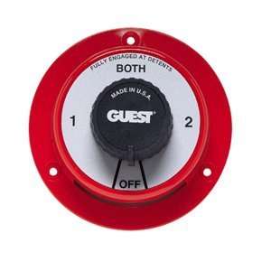
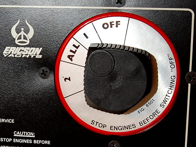
Not much chance of switching through OFF if the order is 2-Both-1-OFF now is there MS. Which has always left me wondering how do folks do it. and why does it get so much attention.
 
Feb 6, 1998
11,674
Canadian Sailcraft 36T Casco Bay, ME
Not much chance of switching through OFF if the order is 2-Both-1-OFF now is there MS. Which has always left me wondering how do folks do it. and why does it get so much attention.

Bill,

It happens all the time despite your instance that it does not, can not or should not happen. Not all battery switches are facing you directly in a panel. They are often poorly located requiring switching them blindly or they can be switched from different approaches and body positions. Easy to flip the wrong way when not paying enough attention...

Battery switch makers know it happens so often that they place the warning right there on it.. I did about eight or nine blown diode re-builds this year alone. All of them but one caused by a pass through the OFF position..

Of course not all battery switches are laid out like a Perko..


Jan 30, 2012
1,123
Nor'Sea 27 "Kiwanda" Portland/ Anacortes
Rob

To get after your other questions - here is one opinion.

One performs work exposing tools to the alternator feed fairly rarely. One can simply disconnect the alternator feed at the house battery fuse. I guess a disconnect remote from the motor room seems an inconvenience. I consider a disconnect and its connections as something that might go wrong so I just eliminate all risk by not having one.

Moving the 24 hour lines direct to to the battery instead of the fuse block will make the battery post a very busy place.

Charles
 
Jan 1, 2006
7,078
Slickcraft 26 Sailfish
For the electrically challenged out there - like me -in summary: So the correct way to switch between batteries is to switch through the both or 1-2 rather than off? This will protect the diodes?
On my 356, you have to get down on your hands and knees, crawl under the nav station, and often need a flashlight, to see the switch. Who knows what happens when a crew member does it!
 
Feb 6, 1998
11,674
Canadian Sailcraft 36T Casco Bay, ME
For the electrically challenged out there - like me -in summary: So the correct way to switch between batteries is to switch through the both or 1-2 rather than off? This will protect the diodes?
On my 356, you have to get down on your hands and knees, crawl under the nav station, and often need a flashlight, to see the switch. Who knows what happens when a crew member does it!
Yes... Passing through OFF with the engine running, and the alternator "loaded", can cause blown diodes. If the alt runs direct to the battery bank with no way to "switch it off" then you can pass through OFF all day long and not hurt the alternator.

Your switch location is not uncommon and is a prime reason so many people blow up their alternators. Very few marine alternators (actually I don't know of any) have "avalanche diodes" in them which can protect against that sort of failure.....
 
Feb 6, 1998
11,674
Canadian Sailcraft 36T Casco Bay, ME
Maine Sail (and others), so now I'm wondering:
-Will the 200A fuse by enough for the starter? I could go larger, but at some point I would need to increase wire size.
200A will be fine I just don't like to see fuses smaller than that..


-Is moving the alternator service disconnect switch out of the engine area a real bad idea, or just non-ideal?
If you don't want a service disconnect you don't need one but you will need to be mindful that the alt wire is live even with the battery switch OFF...


-Is a fuse block for the other "always on" circuits much better than wiring them directly to the battery (still fused appropriately)?
The maximum number of terminals on any one stud/battery post is 4....
 
Nov 16, 2012
1,048
Catalina 310, 2000, #31 31 Santa Cruz
Rob

To get after your other questions - here is one opinion.

One performs work exposing tools to the alternator feed fairly rarely. One can simply disconnect the alternator feed at the house battery fuse. I guess a disconnect remote from the motor room seems an inconvenience. I consider a disconnect and its connections as something that might go wrong so I just eliminate all risk by not having one.

Moving the 24 hour lines direct to to the battery instead of the fuse block will make the battery post a very busy place.

Charles
Thanks. The easiest access to the alternator wiring is actually through an access hole in the port lazarette, where the battery and (proposed switch) are. But it seems like it would be fine to eliminate the switch, and remember that the alternator is always live. :)

I will keep the fuse block for the 24 hour lines.
 
Nov 16, 2012
1,048
Catalina 310, 2000, #31 31 Santa Cruz
200A will be fine I just don't like to see fuses smaller than that..

If you don't want a service disconnect you don't need one but you will need to be mindful that the alt wire is live even with the battery switch OFF...

The maximum number of terminals on any one stud/battery post is 4....
Thanks. I think I've got this pretty well figured out. Again, I really appreciate all of the input from you and others. It's great that you're willing to do that.
 
Nov 16, 2012
1,048
Catalina 310, 2000, #31 31 Santa Cruz
Not much chance of switching through OFF if the order is 2-Both-1-OFF now is there MS. Which has always left me wondering how do folks do it. and why does it get so much attention.
My switch is that way (Perko). You can't switch through OFF, but it's pretty easy to accidently switch from 1 to OFF when you really wanted to go to ALL.

The trade off for wiring the alternator direct to the battery and not being able to blow the diodes is that the alternator is now always live, so you have to be careful with that. It seems worth it to me, especially after reading Maine Sail and Stu Jackson's threads on the subject.