3 amp discharge

Status
Not open for further replies.

kerryb

.
Nov 23, 2009
37
Beneteau Oceanis 400 Lighthouse Point, FL
Well, I am still tracing down my amp draw and have it kinda isolated to the alternator wires. I pulled the alternator and took it back to the shop and they double checked it and said it was OK. I also took the two wire that are causing the problem so he could see the drain. There is an inline devise that I believe is a diode on the black wire. There is also a Y like connector that I am not sure what is, except a connector. The warning light wire and the black wire with diode? are connected together through the Y device and go to a relay and back to the warning light. The drain occurs even when the bottom part of the Y connector is not connected to the relay and warning light, which leaves the diode? and the Y connector as suspect. I believe these can be seen from the previous images I uploaded. search for kerryb to find the thread. If not, I can upload some images that do show it tonight. Does anyone know what these items are?( device in black line and the Y connector. The black wire is connected to the B+ terminal, therefore live when I turn the batt. switches on, and the red wire is connected to the D+.
 

kerryb

.
Nov 23, 2009
37
Beneteau Oceanis 400 Lighthouse Point, FL
As a follow up, the relay in one of the images (green) and the black wire with the unknown devise has something to do with controlling the motor driven refrigerator. I removed the black wire (with unknown devise) from the circuit and the system works fine, alternator charges, no discharge when motor is off. Also noticed during testing with the circuit with the black wire installed that my warning light is on with the ignition switch off. when I turn the ignition switch on, the light goes out.
 

kerryb

.
Nov 23, 2009
37
Beneteau Oceanis 400 Lighthouse Point, FL
I checked it with multi meter diode tester and it read about .4 volts? one way, and nothing the other or I belive my meter reads of. I did test another diode the alternator gave me by using aligator clips. Still had 3 amp discharge. This is assuming that it is a diode. This would leave the Y connector device being something other than a connector. If it is a connector, it is kinda elaborate. You cannot see much in the other images I sent. I will upload better images of the two devices tonight.
 

kerryb

.
Nov 23, 2009
37
Beneteau Oceanis 400 Lighthouse Point, FL
No, that is the reason I need to keep plugging along. I should test the timer to be sure it is not part of the problem.
 

druid

.
Apr 22, 2009
837
Ontario 32 Pender Harbour
If they say the alt is working, let's assume they know what they're doing and proceed ;)

Some alt's will draw current for stator field, etc. or even I think the regulator. As a result, some (most?) will have one wire that is supposed to go through the ignition switch so it doesn't draw power when the engine isn't on. Maybe that's your wire? See if you can find a wiring diagram to see how your alternator is supposed to be wired.

druid
 

kerryb

.
Nov 23, 2009
37
Beneteau Oceanis 400 Lighthouse Point, FL
Hi Druid, I do have the wiring diagram for the engine. I have removed the one black wire with the diode so that it is back to how it came from factory. It works properly this way. The problem is that now the refrigeration does not come on with the black wire out. I believe it was added when the motor driven ref. compressor was installed. I have no time line on that as I have only had the boat 5 years. I do know that he compressor will not run if the alternator is not working. I went through this a couple of years ago when the alternator went out. It has been working up until this problem began. See previous post under kerryb.
 
Nov 6, 2006
10,219
Hunter 34 Mandeville Louisiana
Kerry, is that the power for the electric clutch on the engine drive compressor?? It would be like a car air conditioner compressor clutch and would draw about 3 amperes when the clutch is engaged.. It should be wired so that the engine has to be running before it can be engaged. The refridge thermostat should turn the clutch on and off.. They may have done something strange so that if key is on and the alt light light is off then the clutch may have power if the thermostat tells it to run.. Something in that "logic' circuit must have gone wonky.. is the diode really a zener ? or something like that??
 
Last edited:

kerryb

.
Nov 23, 2009
37
Beneteau Oceanis 400 Lighthouse Point, FL
Yes, it is the compressor clutch that this circuit has been put in to control. It normally runs only when the engine is running and the alternator is working. It is controlled by a 1 hour timer that has to be set instead of a thermostat. And the diode as I have been calling it is one of the mystery pieces. Let me see if I can upload a better image of it.
The first image has the circuit on the floor. The black wire has the diode??? in it where it connects to the red. The other red wire connects to the warning post, D+ The black the B+
The Y device is also in this image. Is that just a connector, or something else?
The second image shows the circuit connected as it originally was. This is where it draws the 3 amps when engine is off. Even if I disconnect the Y, leaving the red and black attached to it and the alternator, it draws 3 amps.
 

Attachments

Benny

.
Sep 27, 2008
1,149
Hunter 320 Tampa, FL
Did you check the timer to insure it is breaking circuit when off?
 

kerryb

.
Nov 23, 2009
37
Beneteau Oceanis 400 Lighthouse Point, FL
Hmmm, no but I will check it Saturday when I get to the boat.
 

Sumner

.
Jan 31, 2009
5,254
Macgregor & Endeavour 26S and 37 Utah's Canyon Country
If they say the alt is working, let's assume they know what they're doing and proceed ;)

Some alt's will draw current for stator field, etc. or even I think the regulator. As a result, some (most?) will have one wire that is supposed to go through the ignition switch so it doesn't draw power when the engine isn't on. Maybe that's your wire? See if you can find a wiring diagram to see how your alternator is supposed to be wired.

druid
I think what druid is saying is the problem if you don't find that the compressor is it. 3 amps is about what an Alternator will pull back through itself if left on.

The little green box looks to be a relay. Does one of the wire off of that "y" go to it?

The one wire (black I believe) that is coming off of the main lug on the alternator is hot as it goes to the batteries. That wire goes to the "Y", correct?

At the "Y" junction one wire goes to the alternator and it should not go to the field (F) terminal as far as I'm concerned. If you have a wire to the field it has to be switched or it will drain like you are saying is happening. Normally there is a wire through and ignition switch that goes to the field wire.

One wire should go from the battery side of the alternator to one of those spades (not the field one), but I can't see how they are labeled.

The field one will help to energize the alternator and make it charge at low rpm's. Usually you don't need it if you rev the motor over a couple thousand rpm and get it energized that way.

I'm wondering if somewhere along the way the wire going to the spade terminals is not on the right one and if it is on the Field it will probably drain the battery.

I also wonder about the purpose of the relay in the picture and if that isn't involved with this.

c ya,

Sum
 

kerryb

.
Nov 23, 2009
37
Beneteau Oceanis 400 Lighthouse Point, FL
I think what druid is saying is the problem if you don't find that the compressor is it. 3 amps is about what an Alternator will pull back through itself if left on.

The little green box looks to be a relay. Does one of the wire off of that "y" go to it?

Yes, it connects to the wire that oes to the warning light and to the relay.

The one wire (black I believe) that is coming off of the main lug on the alternator is hot as it goes to the batteries. That wire goes to the "Y", correct?

Yes, it had what I believe is a diode on it.

At the "Y" junction one wire goes to the alternator and it should not go to the field (F) terminal as far as I'm concerned.
OK, what are you calling the field (F) terminal? the red wire? If so, it is connected I think to the D+, or warning light terminal. You are right in that with just the two wires from the y connected, and not connected to the other side at all, the 3 amp draw is present. But that being said, this is how it was connected before I removed the alternator to take to the shop.
It has been ok for the last two or three years since I had the alternator rebuilt. I have tried to think that maybe I did not label my diagram right before removal, but I can not see any other way that it could be connected. Notice that there is also a black wire from the negative terminal that goes direct to the relay with another wire that jumpers the "switch" side of the relay.

If you have a wire to the field it has to be switched or it will drain like you are saying is happening. Normally there is a wire through and ignition switch that goes to the field wire.

One wire should go from the battery side of the alternator to one of those spades (not the field one), but I can't see how they are labeled.
They are not labeled as far as I can see with the alternator in my lap and a magnifying glass to aid vision. :) There are two wide spades and a narrower one. The red wire is connected to the narrow one...spade would not allow it to fit on the other 2.

The field one will help to energize the alternator and make it charge at low rpm's. Usually you don't need it if you rev the motor over a couple thousand rpm and get it energized that way.

I'm wondering if somewhere along the way the wire going to the spade terminals is not on the right one and if it is on the Field it will probably drain the battery.

I also wonder about the purpose of the relay in the picture and if that isn't involved with this.
I do not believe it is the relay in the wiring diagram. I suspect that it was added to run the clutch compressor, a Saden S505 I believe. The green and white wire connected to it goes up to not the compressor, but another part of the refridge system.

c ya,

Sum
Is it possible that the black wire with the diode should not be connected to the B+ post? The only other post is where the tachometer is connected at the top. It is labeled W.

Thanks for the time you spent studying the problem.
 

kerryb

.
Nov 23, 2009
37
Beneteau Oceanis 400 Lighthouse Point, FL
Dang, hope my answers with in the message above are readable.
 

Sumner

.
Jan 31, 2009
5,254
Macgregor & Endeavour 26S and 37 Utah's Canyon Country
Is it possible that the black wire with the diode should not be connected to the B+ post? The only other post is where the tachometer is connected at the top. It is labeled W.

Thanks for the time you spent studying the problem.
No, I feel 99% sure that the black one is where it should be. The one I question is the red one above it that is pushed onto one of the 3 spade terminals that I think I see in the picture. Do you have a better shot of those spade terminals. Any lettering by them, like an "F". Also do you have a name, part number, ???, anything where I could see that alternator on the Internet?

I'm just wondering if in all that you have done has that red wire been put on the wrong terminal or if the other side of the "Y", not the black wire, has been switched from the alternator to what looks like a relay.

I can also see where the diode could possible be in there so that the alternator gets excited, but can't let current flow the other way and drain the battery. I know you checked the diode, but if you have another I would think about replacing this one in "this" wiring harness.

I'd still like to know the purpose of the relay? When the timer goes off does the engine actually start and run for a while.

I went back and read where you mentioned a warning light. Are you sure it is a warning light and that is all?


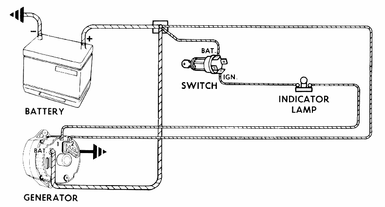
In the diagram the wire going through the switch and to the #1 terminal goes through that light. It excites the alternator so that it will start charging at a lower RPM and it will act as a warning light and light when the alternator isn't charging like when you turn the key on before the car starts. Your warning light could possibly be in the circuit for the same reason. I can't figure out why you only have one wire going to the terminals above the Bat lug below. Most alternators need 2 up there unless they are a one wire alternator then they need none, only the one wire to the 'bat' terminal. They are internally regulated. I don't think that is what you have though.

Good luck and if you get it figured out I'd like to know what it was,

Sum
 

kerryb

.
Nov 23, 2009
37
Beneteau Oceanis 400 Lighthouse Point, FL
Here is shots of the back of the alternator and a couple of shote of the actual wiring diagram and my sketch of the relay by the alternator and how it is wired.
 

Attachments

kerryb

.
Nov 23, 2009
37
Beneteau Oceanis 400 Lighthouse Point, FL
First one , 2 is the alternator and the wiring below deck. The second one is the cockpit panel. I am heading over to put the alternator back on and install a new charger.
 

Sumner

.
Jan 31, 2009
5,254
Macgregor & Endeavour 26S and 37 Utah's Canyon Country
I sent you a PM with my phone number. Call me if you want. After seeing the wiring diagram I don't think that wiring on there now is orginal. I might have some ideas,

Sum
 
Status
Not open for further replies.